
DDP096 - Pump DANFOSS - Free user manual and instructions
Find the device manual for free DDP096 DANFOSS in PDF.


| Product Type | Hydraulic Axial Piston Pump |
| Model | DDP096 |
| Brand | Danfoss |
| Displacement | 96 cm³/rev |
| Maximum Pressure | 350 bar (continuous) |
| Maximum Speed | 3000 rpm |
| Flow Rate (at rated speed) | 288 L/min |
| Mounting Flange | SAE B 2-bolt |
| Port Connections | SAE O-ring (pressure & suction) |
| Weight | Approx. 25 kg |
| Dimensions (L x W x H) | 320 x 180 x 180 mm |
| Shaft Type | Straight keyed (per SAE) |
| Seal Material | Nitrile (Buna-N) standard |
| Housing Material | Cast iron |
| Operating Temperature Range | -20°C to +80°C |
| Recommended Hydraulic Fluid | ISO VG 46 mineral oil |
| Filtration Requirement | ISO 4406 18/16/13 or better |
| Noise Level (at rated conditions) | <80 dB(A) |
| Maintenance | Check fluid level & condition weekly; replace filter annually |
| Safety Features | Built-in pressure relief valve; shaft seal leakage indicator |
| Spare Parts Availability | Seal kit, valve plate, piston assembly, bearing kit |
| Repairability | Field serviceable with standard tools; replacement parts available |
Frequently Asked Questions - DDP096 DANFOSS
User questions about DDP096 DANFOSS
0 question about this device. Answer the ones you know or ask your own.
Ask a new question about this device
Download the instructions for your Pump in PDF format for free! Find your manual DDP096 - DANFOSS and take your electronic device back in hand. On this page are published all the documents necessary for the use of your device. DDP096 by DANFOSS.
USER MANUAL DDP096 DANFOSS
Technical Information
Digital Displacement
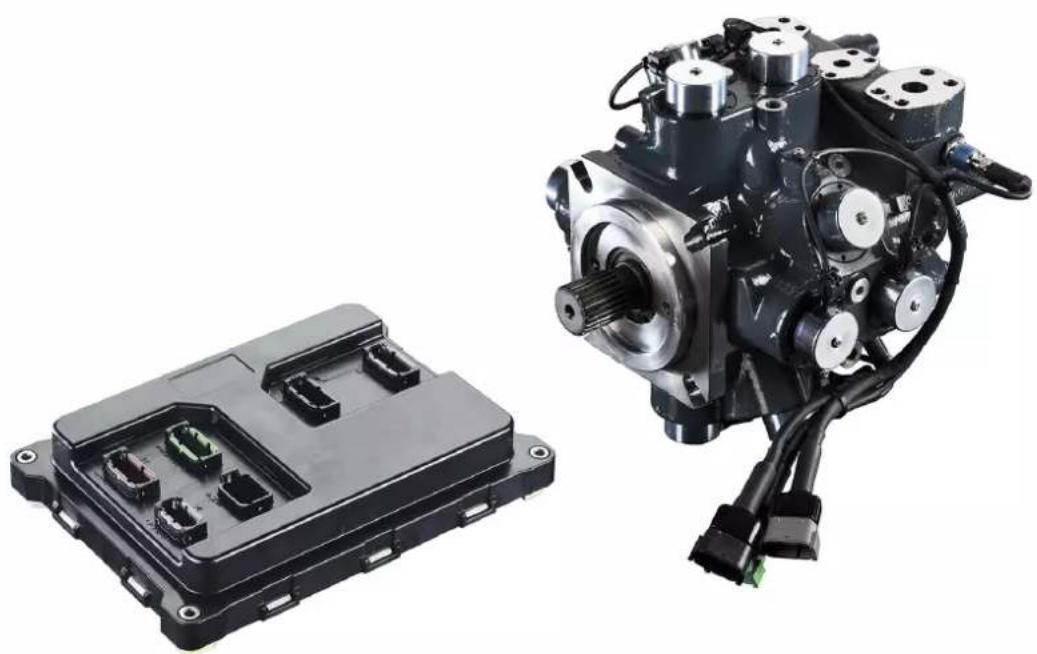
DDP096 pump and DPC12 controller
natural_image
Two mechanical components: a black plastic enclosure with multiple ports and a black hydraulic pump with visible shafts and wiring (no text or symbols)Revision history Table of revisions
| Date Changed Rev | ||
| October 2023 Revised to reflect updated specifications 0202 | ||
| June 2021 Added new Gen 1 content; recreated document structure 0201 | ||
| December 2019 Revised to reflect 420 bar limit and updated software features 0102 | ||
| October 2019 First edition: 280 bar, industrial 0101 | ||
Contents
General information
Overview....5
About the DDP....5
Theory of operation....5
Multi-outlet pump....6
Features and benefits....8
General safety warnings....8
Fluid under high pressure....8
OEM responsibility....9
Pressure relief....9
Failure and fault states....9
Intended use....9
Improper use....10
Personnel qualifications....10
Technical specifications
DDP096 pump specifications....11
DDP general specifications....11
DDP fluid specifications....11
DDP mechanical specifications....11
DPC12 controller specifications....13
DPC12 input power supply....13
Fuses....13
Pressure sensors for DPC12....13
Non-volatile memory write/erase ratings....14
General ratings....14
Environmental standards and criteria....14
LED messages....15
DPC12 housing....15
DDP characteristics
Performance....16
Overall pump efficiency....16
Idle losses....16
Pump discharged flow and shrinkage....17
Input torque....18
Electronic control losses....19
Noise characteristics....19
Control operation
Control modes, limits, and features.... 20
Control modes and sources....20
Limits....20
Other features....21
Control diagrams....22
Example use cases....24
Controller interaction....24
Overview....24
PLUS+1 ^® CAN/USB gateway....24
Configuration and tuning....24
Commissioning mode....25
Diagnostics and errors....25
Model code
DDP model code....26
DDP part options....27
Mechanical installation
Pump transport and handling....29
Storage....30
Installation requirements....30
Contents
Pump arrangement....30
Pump shaft coupling....30
Understanding and minimizing system noise....31
Air removal....31
Removing air by gravity....31
Removing air with an auxiliary pump....31
Removing air through the DDP outlet port....32
Removing air by submersion....33
Flushing....33
Filtration....33
Controller mounting....33
Pump dimensions....35
Common dimensions....35
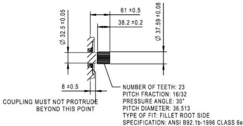
Shaft end view dimensions....36
Flange dimensions....37
Side view dimensions....38
Top view dimensions....41
Rear view dimensions....42
Single-outlet pump dimensions....43
Multi-outlet pump dimensions....45
Multi-outlet pump side view dimensions....46
Multi-outlet pump rear view dimensions....48
Controller dimensions....50
Electrical installation
Installation requirements....51
Wiring overview....51
Machine wiring guidelines....52
Machine welding guidelines....53
CAN bus installation....53
System diagnostic connector....53
Fuses....53
Grounding....53
Hot plugging....54
Connectors....55
Pump connectors....56
Controller connectors....57
Commissioning and troubleshooting
Basic commissioning procedure....58
Commissioning and troubleshooting with PLUS+1 Service Tool....58
Initial procedure....58
Commissioning DDP valves and hydraulic installation....58
Further system commissioning and validation....59
Symptoms and diagnosis....60
Serviceability....60
General information
Overview
This document contains important information about the safe operation and control of the open circuit hydraulic Digital Displacement ^® Pump DDP096 and its partnered digital pump controller DPC12. Throughout this document the complete partnered product will be referred to as the Digital Displacement ^® Pump or DDP.
Guidance is given on the transportation, commissioning and operation of the pump. For disposal please contact Danfoss.
All safety guidance provided in this document must be followed. Relevant residual risks and control measures are outlined.
This document is not a substitute for appropriate professional training and competency dealing with hydraulic circuits. Only competent persons should install, operate or maintain the pump and controller.
About the DDP
Digital Displacement is a new hydraulic pump technology based on a radial piston pump design. An electronic controller selectively enables each piston by actuating a corresponding on/off valve. In this way, the pump displacement is digitally variable resulting in fast and accurate flow control. Digital Displacement ^® pumps have high efficiency and very low idle losses because they use only as many pistons as are needed to meet the demand.
Theory of operation
Check valves connect each of the pump's piston chambers to the inlet and outlet, as shown below.
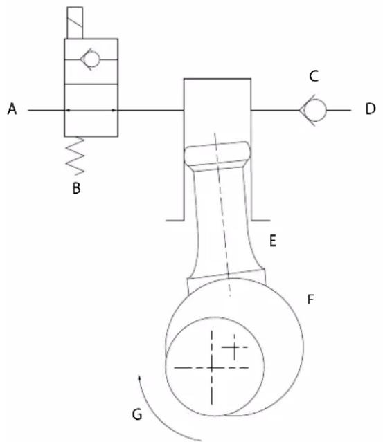
A Inlet
B Inlet check valve
C Outlet check valve
D Outlet
E Piston
F Cam
G Shaft rotation
The outlet check valve is passive. The inlet check valve is actively controlled and is normally open and can be closed by energizing a solenoid coil. As the pump's input shaft rotates, it turns an eccentric cam which pushes the piston up and down in the piston chamber. The controller determines whether or not the piston will pump fluid to the outlet. If the piston is idling, the inlet check valve is not energized and the inlet check valve remains in the open position. The fluid displaced by the piston moves freely back and forth from the inlet. No fluid is discharged to the outlet.
To pump each piston, the controller closes the solenoid valve when the piston is at bottom dead center. The inlet check valve closes and the piston forces the fluid through the outlet check valve. When the
General information
piston reaches top dead center, the inlet check valve reopens and fluid is drawn from the inlet into the piston chamber as the piston moves out to begin another cycle.
The DDP has 12 pistons which each displaces 8 cc of fluid per stroke for a total displacement volume of 96 cc/rev. The pump geometry is designed so that the pistons are evenly spaced 30° apart. Every piston is enabled at full displacement (displacement fraction F_d=1 ), and every piston is disabled at F_d=0 . For 0 < F_d<1 , the controller uses a sequence of enabled and disabled pistons which are represented by ones and zeros respectively in the following table of examples.
| Displacement Fraction Piston Sequence | Sequence Length | |
| 0.5 01...2 | ||
| 0.25 0001...4 | ||
| 7/12 = 0.583 010101101011...12 | ||
| 19/24 = 0.792 111101111011 110111101110...24 |
The desired displacement fraction is achieved as an average over time. Some displacement fractions can be achieved with short sequences like 01... or 001... Other displacement fractions are achieved with longer sequences. For example, F_d = 0.792 = 19/24 has 10 active pistons during the first revolution and 9 active pistons during the second revolution. F_d = 0.51 requires a repeating sequence of length 100 with 51 ones and 49 zeros. Any value of F_d can be achieved with a sufficiently long binary sequence.
The controller does not use fixed or pre-programmed sequences of on and off pistons. At every 30 degrees of shaft rotation, the controller determines whether to enable the next piston based on the current F_d command and the history of pistons enabled. In the preceding table, the commanded displacement is constant, so the piston sequence is periodic. The same pistons are not necessarily enabled or disabled, but can change with each shaft rotation.
The DDP can operate in various control modes including pressure control, load sensing, flow control, displacement control, torque or power control and combinations of these. The control modes are monitored by the DPC12 pump controller based on sensor inputs and configured with parameters and limits at a software level. For instance, to regulate the pump pressure in pressure control mode, the controller compares the measured pressure to the desired pressure and calculates a displacement command with a proportional-integral control algorithm.
Multi-outlet pump
The DDP096 is composed of 12 pistons and valves (i.e. 12 pumping units). These pumping units are divided into four groups of three called pumplets. The DDP can be perceived as a combination of four independent pumplets producing each up to 24 cc/rev, given its unique radial design and digital control.
The DDP096 is available either as a single-outlet endcap or a multi-outlet endcap. The single-outlet DDP has one inlet and one outlet like other conventional hydraulic pumps. However, the multi-outlet DDP leverages the four pumplets to offer multiple outputs from a single pump with independent flows, pressures, and control modes.
General information
Three-outlet DDP096 exploded view
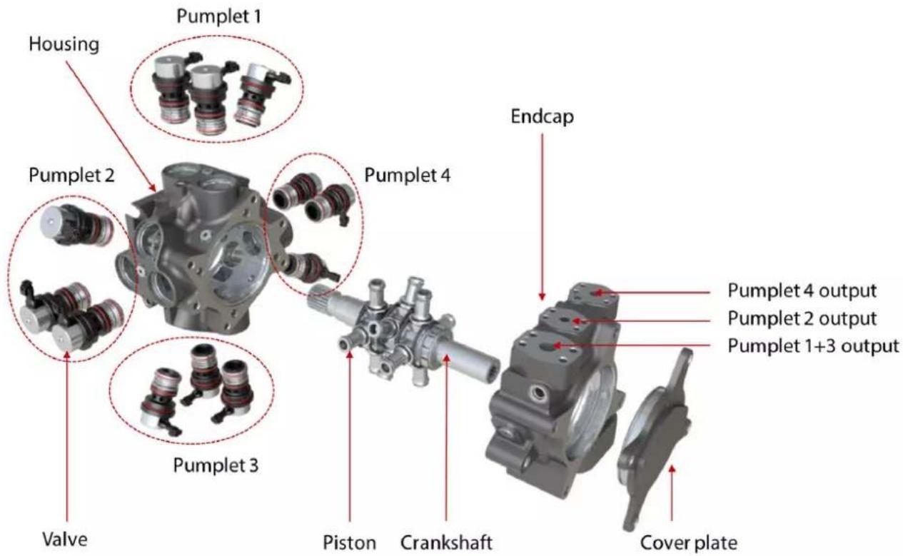
The multi-outlet endcap provides three outlets to the DDP:
• 2 outlets producing up to 24 cc/rev each
• 1 outlet producing up to 48 cc/rev
With this multi-outlet endcap, different displacements are achievable with a ganging manifold to suit an application using two services. A service is one level higher than the pump outlet and represents the number of fluid consumers of the DDP. A service is essential to control the DDP096 with the DPC12.
Services diagram
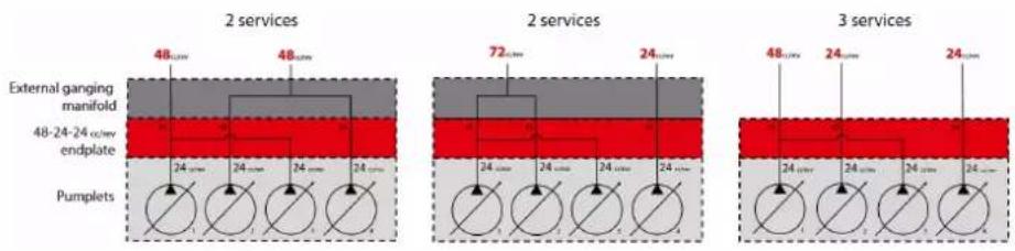
For 2-service operation (Service 1 and Service 2), two configurations are possible:
P1 / (P2 + P4) [48 / 48 cc/rev]
• (P1 + P2) / P4 [72 / 24 cc/rev]
P1, P2, and P4 represent the outlet ports of the multi-outlet DDP096 endcap. (P2+P4) means that the P2 and P4 ports must be connected with a ganging manifold. Refer to Pump dimensions for more information on ports.
General information
Service 1 and Service 2 must be selected at the software level and configured accordingly. Refer to Software manual (document number BC404560709540) for more information.
Features and benefits
Features and benefits of the DDP are as follows.
Most energy-efficient system
• Exceptional full and part load performance
• Low idle losses at any pressure
- Enables significantly lower system losses – reduced throttling, engine downsizing or downspeeding
• Works seamlessly in diesel, hybrid or electric machines
Fastest response time
• Power delivered immediately – more responsive to operator demand
• Increased productivity with more usable hydraulic power
• Optimized engine torque management – doing more with less
Digitally controlled
• Software defined control over CAN J1939
• Common hardware – wide range of control modes
• Predictable and precise closed-loop control with integrated sensors
• Performance monitoring, diagnostics, error handling, etc.
Compact and quiet
• Multiple independent outlets
• Compact and robust design
• Better sound quality than axial piston pumps
Expanded modularity
• Inventory reduction with common hardware
- PLUS+1 ^® compliant
• Easy integration with telematics
• Standardized connector interface
• Through-drive options
General safety warnings
The DDP has been manufactured according to the generally accepted rules of hydraulic machine design and uses the latest advanced valve concepts to maximize operating efficiency and user controllability.
Fluid under high pressure
Escaping hydraulic fluid under pressure can have sufficient force to penetrate skin causing serious injury and/or infection. Additionally, the fluid may cause burns. Use caution when dealing with hydraulic fluid under pressure. Always relieve pressure in the system before removing hoses, fittings, gauges, or other components. Never use hands or any other body parts to check for leaks in a pressurized component; seek medical attention immediately if you are cut by hydraulic fluid.
General information
OEM responsibility
The OEM of a machine or vehicle in which Danfoss products are installed has the full responsibility for all consequences that might occur. Danfoss has no responsibility for any consequences, direct or indirect, caused by failures or malfunctions.
- Danfoss has no responsibility for any accidents caused by incorrectly mounted or maintained equipment.
- Danfoss does not assume any responsibility for Danfoss products being incorrectly applied or the system being programmed in a manner that jeopardizes safety.
- All safety critical systems shall include an emergency stop to switch off the main supply voltage for the outputs of the electronic control system. All safety critical components shall be installed in such a way that the main supply voltage can be switched off at any time. The emergency stop must be easily accessible to the operator.
- The hydraulic system must also be designed to withstand an emergency shutdown where hydraulic flow will stop, and pressure may drop significantly.
Warning
There is the potential to cause personal injury or damage to equipment if the following instructions and warning are not followed.
- Please read these instructions thoroughly before commissioning the pump.
- Keep these instructions in an accessible location and always pass them on to the end user of the pump.
- Consult with Danfoss if there are any questions about the intended use of the pump or safety implications from operating the pump.
- Operating conditions and technical data given in the data sheet must be followed at all times.
Pressure relief
The pump is not supplied with any mechanical pressure limiting device as standard. Pressure transducers present on the pump are for pressure compensation and can not substitute as a safety device.
A pressure relief valve rated for full flow in the hydraulic circuit is important in protecting the product and personnel.
The OEM is responsible for designing the system to mitigate potential unsafe situations, such as providing adequate pressure relief.
Failure and fault states
The hydraulic system must be able to cope with different flows than intended due to a mechanical or controller fault.
If electrical power to the DPC12 controller is lost, the DDP096 pump should output zero flow. Some software faults also cause the DDP096 to stop providing flow. If zero output flow is an undesirable failure/fault mode in the application, means of providing backup flow must be designed into the system.
Intended use
Digital Displacement ^® pumps are components in terms of the EU machinery directive 98/37/EC. Hydraulic pumps are not ready to use machines as described in the EU machine directive. Digital Displacement ^* pumps are produced with the sole intention of being incorporated within a machine or further assembly to form a machine or system. The product may only be fully commissioned after it has been installed in the machine or system for which it is intended.
The Digital Displacement* pump produces and controls the flow of hydraulic fluid most commonly with the function of regulating the output pressure. It is assumed that a flow control device, such as a closed center proportional valve, is present in the system between the pump and the controlled load. Other applications may be acceptable but should be discussed with Danfoss first.
General information
Improper use
Warning
Digital Displacement ^x pumps may not be used in explosive environments. Digital Displacement ^x pumps may not be used in life critical applications.
Please contact Danfoss for further information on use in specific applications.
Personnel qualifications
The system operates with high pressure fluid. Assembly and disassembly of the pump for maintenance purposes is only to be carried out by Danfoss or a qualified service technician authorized by Danfoss.
Installation of the pump and electrical equipment must be carried out by suitably qualified personnel with experience and knowledge of working with hydraulic and electrical systems.
Technical specifications
DDP096 pump specifications
DDP general specifications
The below table contains information for displacement, pressure, torque, and temperature.
| Description Value Units | |||
| Maximum displacement 96 [5.86] cm | ^3 /rev [in ^3 /rev] | ||
| Available rotation (viewed from shaft end of the pump) Clockwise (CW) [R] | |||
| Counterclockwise (CCW) [L] | |||
| Outlet pressure Maximum peak 450 [6526] bar [psi] | |||
| Maximum continuous 420 [6091] | |||
| Minimum continuous 15 [218] | |||
| Inlet pressure (absolute) ^1 | Minimum 0.8 [12] bar [psi] | ||
| Maximum 3.5 [50] | |||
| Input speed Continuous range 500 - 2200 min | ^-1 (rpm) | ||
| Inlet fill ^2 | 2500 | ||
| Maximum 2600 | |||
| Flow at specific speed and maximum displacement (theoretical) | 144 [38] @1500 rpm173 [45.6] @1800 rpm | L/min [US gal/min] | |
| Weight (without through drive) approx. | 50 [110] | kg [lb] | |
| Filling capacity | 2.5 [0.66] | L [US gal] | |
| Mass moment of inertia approx. | 0.0013 [0.00096] | kg·m ^2 [slug·ft ^2 ] | |
| Ambient temperature | Minimum -40 [-40] | °C [°F] | |
| Maximum 105 [221] | |||
^1 Size hoses or piping appropriately to ensure the minimum pressure condition is satisfied.
^2 Highest shaft speed with inlet pressure of 1 bar absolute (2100 rpm with minimum inlet pressure)
DDP fluid specifications
| Description | Value | Units | |
| Viscosity | Minimum intermittent | 8 | cSt |
| Minimum continuous | 10 | ||
| Recommended range | 16 - 40 | ||
| Maximum for cold start 8000 | |||
| Temperature | Minimum for cold start -40 [-40] | °C [°F] | |
| Recommended range | 20 - 80 [68 - 176] | ||
| Maximum continuous | 95 [203] | ||
| Maximum intermittent | 100 [212] | ||
| Cleanliness per ISO4406:1999 | Recommended | 17/15/12 | |
| Minimum | 18/16/13 | ||
Special procedure is required for cold start. Contact your Danfoss representative for details.
DDP mechanical specifications
| Description | Value | Notes |
| Front mounting flange | SAE C 4-bolt | Flange 127-4 adhering to ISO 3019-1 (SAE J744:1996) |
| Front input shaft | 23 tooth 16/32 pitch | Spline per ANSI B92.1b-1996 class 6e |
Technical specifications
| Description Value Notes | ||||
| Inlet/Suction port S DN 51 (Ø 51 mm) Shipped with steel cover. For more information, | see pump dimensions. | |||
| Outlet/Pressure port(s) Single outlet P DN 25 (Ø 25 mm) | ||||
| Bleed port plugs 7 M14 x 1.5 steel plugs Per ISO 6149-1 | ||||
| Handling brackets 3 (2 at the rear and 1 on pumplet 1) Only intended for lifting pump and Danfoss supplied sensors/wiring | ||||
| Pump wiring harness connectors | DTM04-12PC (green) – C3DTM04-12PA (grey) – C4DTM04-12PB (green) – C5 | C3 is for the sensor harnessC4 is for the coil harness “A”C5 is for the coil harness “B” | ||
| Sensors included in DDP | 1 speed and temperature sensor1 (to 3) pressure sensor(s) | The DDP has a pressure sensor on each service. | ||

Warning
Do not substitute the factory supplied sensors for any other type as it can lead to irreversible damage.
Refer to the DDP096 Parts Manual (document number AX398965058218) for replacement parts. Contact your Danfoss representative for more details.
All pump connectors are rated to IP67 and IP6K9K when connected with suitable mating connectors.
Technical specifications
DPC12 controller specifications
DPC12 input power supply
| Description | Minimum Max | mum Unit Notes | ||
| Supply voltage - continuous range | 12 32 VDC For | operation on | 2V or 24V systems. Warnings may occur if this range is exceeded. | |
| Supply voltage - maximum range | 9 36 VDC Unex | expected shutdown | down may occur | if this range is exceeded. Damage may occur if >36V applied for long periods of time. |
Controller power consumption
| Description Typical Unit | ||
| Approximate power consumption (full displacement) 1 W/(L/min) | ||
| Approximate idle power consumption (no displacement) 7 W |
The DPC12 draws a variable pulsed load from the coil power supply. Power consumption values are mean. Higher peak currents to be expected.
Coil harness extension wiring
| Description Value Unit Notes | |||
| Maximum pump-to-controller extension cable length | 14AWG: 6.416AWG: 3.918AWG: 2.620AWG: 1.6 | m Corresponds to 55 mΩ (@20 °C) one-way resistance of pump-to-controller extension cable (from pump connector C4/C5 to controller connector C4/C5, excluding pins and crimps). | |
Fuses
To simplify fusing and minimize wiring complexity, it is recommended to splice each group of four of the 8-pin DEUTSCH power connector's conductors into a single larger conductor of at least 5mm ^2 CSA as close to the DPC12 as possible. The main conductor should be protected by a 30A fuse for 12V or 24V systems.
If this splicing arrangement is not possible, fusing the individual conductors of the DPC12 power connector may be necessary if these individual conductors are exposed to possible damage, or are not able to pass the current required to blow the main fuse in the event of a fault. In this case divide the recommended fuse value by four, so 7.5A for 12V or 24V systems.
| Number of conductors 1 | 4 | |
| 12/24V system | 30A main | 7,5A /pin |
Warning
When powering the DPC12 from a current limited power supply, use special consideration to ensure power supply has enough margin to blow the chosen fuse. For example, pairing a 40A fuse with a current limited power supply of 40A is potentially dangerous. The fuse current must be exceeded by a large margin to guarantee the fuse blows before hardware damage.
Pressure sensors for DPC12
While the DDP096 pump is already equipped with pressure sensor(s), additional pressure sensor(s) may be required for load sensing operation in addition to software configuration.
Technical specifications
The DPC12 is only compatible with 4-20 mA pressure sensors. Please refer to the DDP096 Parts Manual (document number AX398965058218) to use the recommended pressure sensors.
Non-volatile memory write/erase ratings
| Description Value Unit | ||
| EEPROM write/erase cycles* | 4 × 10^6 |
* Minimum valid cycles over entire operating temperature range
General ratings
Environmental
| Description Minimum Maximum Unit | |||
| Operating ambient temperature ^1 | -40 [-40] 70 [158] °C [°F] | ||
| Storage temperature -55 [-67] 90 [194] °C [°F] | |||
| Ingress Protection (IP) ratings ^2 | IP67 |
^1 70°C is the maximum for continuous full load, but up to 90°C is permissible for non-continuous, partial load. Overheating will cause errors and thermal shutdown.
^2 Documented IP ratings are valid only when the mating connectors are in place and unused connector pin positions have sealing plugs installed.
Product compliance
| Description EU Directive | |
| CE rating - | |
| EMC 2014/30/EU | |
| RoHS 2011/65/EU | |
| REACH (EC) No 1907/2006 |
CAN bus
| Description Value Unit | ||
| Available baud rates 125 kbps | ||
| 250^* | ||
| 500 | ||
| 1000 |
* Default value; see the DPC12 software manual for more information.
Environmental standards and criteria
Climate environmental standards
| Description Applicable standard | |
| Storage operating IEC 60068-2-1, test Ab | IEC 60068-2-2 test Bb |
| Operating temperature IEC 60068-2-1, test Ab | IEC 60068-2-2, test Bd |
| Degree of protection (IP) | IEC 60529 |
Technical specifications
Electrical and electromagnetic standards
| Criteria Applicable standard | Additional information | |
| EMC emissions ISO 13766 | Electromagnetic compatibility for earth moving machinery | |
| EMC immunity ISO 13766 | Electromagnetic compatibility for earth moving machinery | |
| Electrostatic discharge | EN 61000-4-2SAE J1113-13 | Electrostatic discharge immunity test |
| Auto electrical transients | ISO 7637-2ISO 7637-3 | Road vehicles — Electrical disturbances from conduction and coupling |
For more information about criteria and standards please contact your Danfoss representative.
LED messages
LED characteristics meaning
| Characteristic LED Indication | ||
Magenta; blink rate 1.5 Hz Device is in  | pde | |
Blue; fast irregular blinking Device is  | cation software | |
Yellow; blink rate 1.5 Hz Device is in COMMISSIONING pde  | pde | |
| Yellow; continuous Device is either writing for DM12 message to enable the pump, in INIT state directly after power up, or in DISABLED state | ||
Green; continuous Device is in ACTIV  | ||
Red; continuous Device is in ERROR o  | ||
Red; blinking J1939 address claim fault  | ||
Alternating red/green Device is in LIM  | is no severe error | |
Refer to the DPC12 Software manual for details on operation modes.
Refer to section DPC12 input power supply on page 13 for location of LED on the DPC12 controller.
DPC12 housing
The DPC12 housing features a snap together assembly. The controller weighs 3 kg. Once assembled at the factory, the housing cannot be opened for service.
The DPC12 controller is not field serviceable. Opening the DPC12 housing voids the factory warranty.
DDP characteristics
Performance
Overall pump efficiency
The overall pump efficiency is the ratio of the hydraulic output power to the mechanical input power.
DDP096 Overall efficiency map
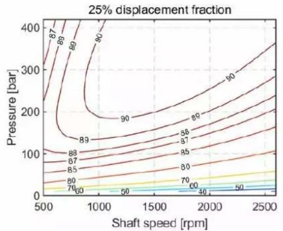
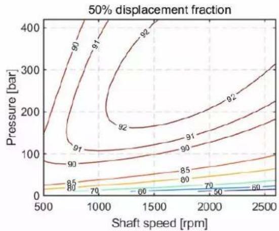
contour
| Shaft speed [rpm] | Pressure [bar] | Displacement Fraction | | ----------------- | -------------- | --------------------- | | 500 | 150 | 80 | | 750 | 100 | 70 | | 1000 | 120 | 85 | | 1250 | 130 | 90 | | 1500 | 140 | 91 | | 1750 | 150 | 92 | | 2000 | 160 | 92 | | 2250 | 170 | 92 | | 2500 | 180 | 92 |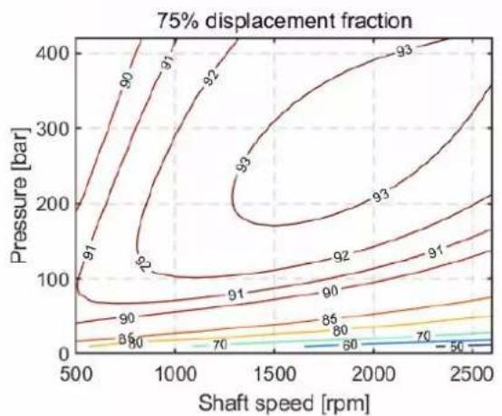
contour
| Shaft speed [rpm] | Pressure [bar] | Value Label | | ----------------- | -------------- | ----------- | | 500 | 100 | 91 | | 500 | 200 | 90 | | 500 | 300 | 85 | | 500 | 400 | 70 | | 1000 | 100 | 92 | | 1000 | 200 | 91 | | 1000 | 300 | 86 | | 1000 | 400 | 70 | | 1500 | 100 | 93 | | 1500 | 200 | 92 | | 1500 | 300 | 85 | | 1500 | 400 | 70 | | 2000 | 100 | 93 | | 2000 | 200 | 92 | | 2000 | 300 | 86 | | 2000 | 400 | 70 | | 2500 | 100 | 91 | | 2500 | 200 | 86 | | 2500 | 300 | 80 | | 2500 | 400 | 70 |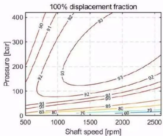
contour
| Shaft speed [rpm] | Pressure [bar] | Displacement Fraction | | ----------------- | -------------- | --------------------- | | 500 | 0 | 85 | | 500 | 50 | 80 | | 500 | 100 | 85 | | 500 | 150 | 90 | | 500 | 200 | 90 | | 500 | 250 | 90 | | 1000 | 0 | 70 | | 1000 | 50 | 80 | | 1000 | 100 | 85 | | 1000 | 150 | 90 | | 1000 | 200 | 92 | | 1000 | 250 | 92 | | 1500 | 0 | 60 | | 1500 | 50 | 70 | | 1500 | 100 | 80 | | 1500 | 150 | 85 | | 1500 | 200 | 93 | | 1500 | 250 | 93 | | 2000 | 0 | 70 | | 2000 | 50 | 80 | | 2000 | 100 | 85 | | 2000 | 150 | 93 | | 2000 | 200 | 93 | | 2000 | 250 | 93 | | 2500 | 0 | 70 | | 2500 | 50 | 80 | | 2500 | 100 | 85 | | 2500 | 150 | 93 | | 2500 | 200 | 93 | | 2500 | 250 | 93 |Inlet pressure 1.0 bar abs – inlet temperature 50°C with ISO VG46 oil
Idle losses
In a Digital Displacement* pump each piston chamber is isolated from the outlet line by a high-pressure valve, acting as a check valve. As a result, the idle losses of the DDP096 are independent from the outlet pressure.
While in idling mode, the discharge flow of the pump is exactly 0 L/min.
See Theory of operation on page 5 for more information.
DDP characteristics
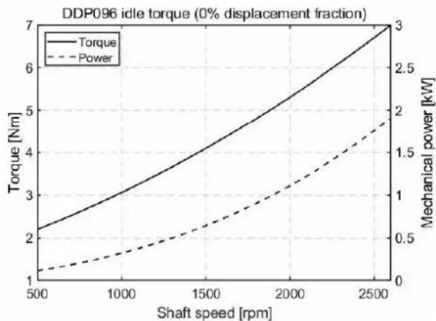
line
| Shaft speed [rpm] | Torque [Nm] | Mechanical power [kW] | | ----------------- | ----------- | ---------------------- | | 500 | 2.2 | 0.3 | | 1000 | 3.0 | 0.5 | | 1500 | 4.0 | 0.8 | | 2000 | 5.0 | 1.2 | | 2500 | 7.0 | 2.0 |Pump discharged flow and shrinkage
Pump shrinkage
The DDP096 output flow rate is proportional to the displacement fraction as the number of valves being enabled increases linearly with the displacement fraction. The discharged flow rate will also decrease as the pressure increases. In conventional machines, such a decrease in flow is normally associated with volumetric efficiency, as the energy is lost as leakage. With Digital Displacement® pumps, this decrease is due to pump shrinkage and is mostly caused by the compression of oil. Most of the energy stored in the compressed oil is then transferred back to the crankshaft when the piston chamber is depressurized after top dead center. The conventional definition of volumetric efficiency (defined by ISO4409:2019) is therefore inappropriate for Digital Displacement® pumps.
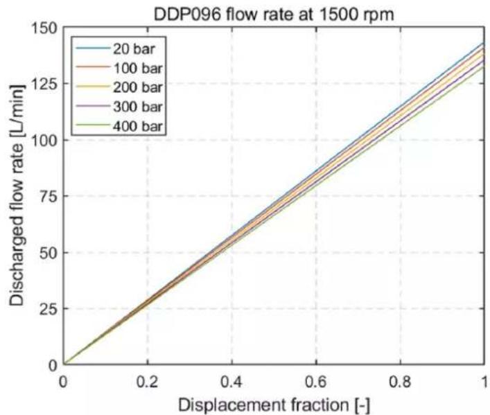
line
| Displacement fraction [-] | 20 bar | 100 bar | 200 bar | 300 bar | 400 bar | | ------------------------- | ------ | ------- | ------- | ------- | ------- | | 0.0 | 0 | 0 | 0 | 0 | 0 | | 0.2 | 25 | 25 | 25 | 25 | 25 | | 0.4 | 50 | 50 | 50 | 50 | 50 | | 0.6 | 75 | 75 | 75 | 75 | 75 | | 0.8 | 100 | 100 | 100 | 100 | 100 | | 1.0 | 125 | 125 | 125 | 125 | 125 |Discharged flow
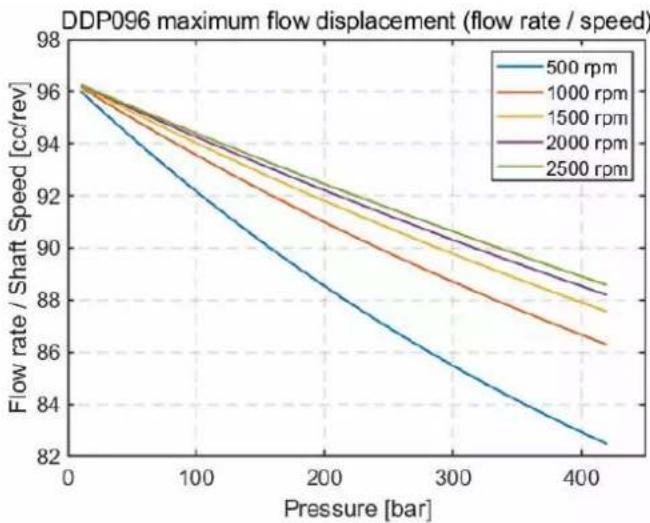
To estimate the actual DDP096 discharged flow rate at a given pressure and shaft speed, the shaft speed should be multiplied by the "Flow rate / Shaft Speed" (i.e. pump displacement) presented in the graph below. For example, at 400 bar and 2500 rpm the DDP096 pump displaces a maximum of 88.5 cc/rev, equivalent to 177 L/min.
DDP characteristics
As each valve actuation is done independently, the pump shrinkage ratio is independent of the pump displacement demand. Therefore, when requesting 25% of pump output flow, the pump will displace exactly 25% of maximum flow in the same condition of pressure speed and viscosity.
line
| Pressure [bar] | 500 rpm | 1000 rpm | 1500 rpm | 2000 rpm | 2500 rpm | | -------------- | ------- | -------- | -------- | -------- | -------- | | 0 | 96.0 | 96.0 | 96.0 | 96.0 | 96.0 | | 100 | 93.0 | 94.0 | 94.5 | 94.8 | 95.0 | | 200 | 89.0 | 91.0 | 92.5 | 93.0 | 93.5 | | 300 | 85.0 | 88.0 | 89.5 | 90.5 | 91.5 | | 400 | 82.0 | 86.0 | 87.5 | 88.5 | 89.5 |Input torque
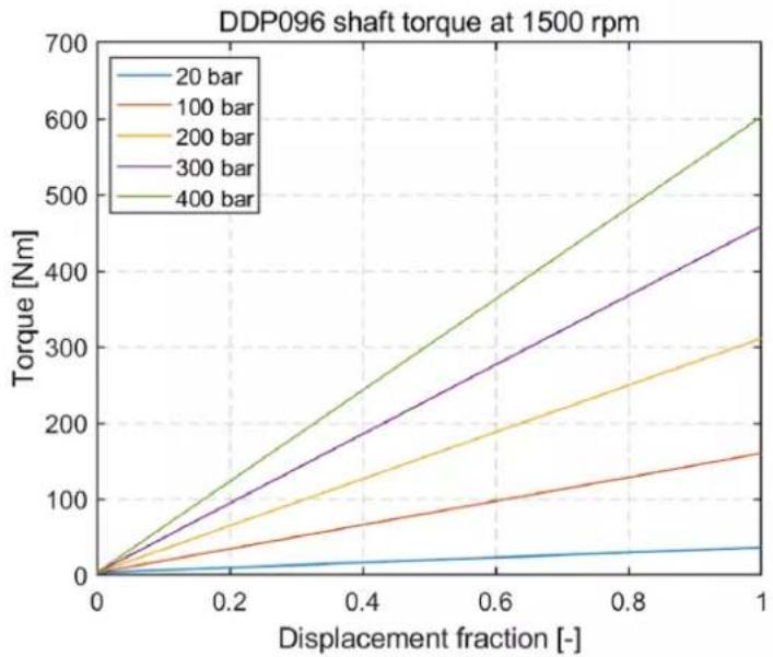
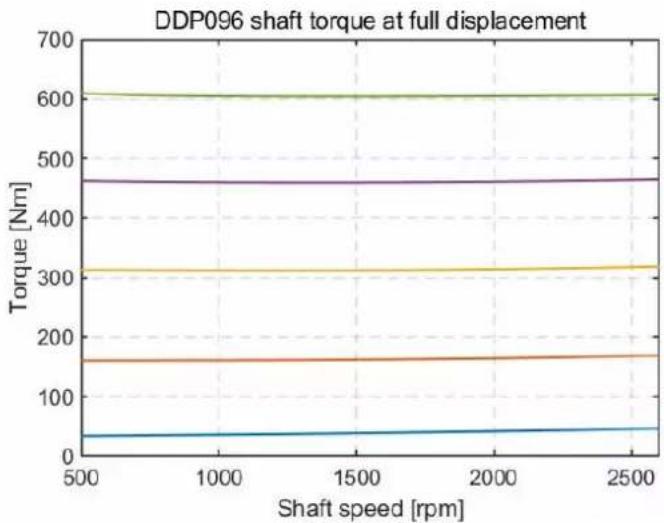
Due to internal compressed energy recovery, the torque and input power follow the same rule as the pump discharge flow; the input torque and power increases less with pressure than would be expected from the theoretical value.
line
| Displacement fraction [-] | 20 bar | 100 bar | 200 bar | 300 bar | 400 bar | | -------------------------- | ------ | ------- | ------- | ------- | ------- | | 0.0 | 0 | 0 | 0 | 0 | 0 | | 0.2 | ~10 | ~30 | ~60 | ~100 | ~150 | | 0.4 | ~20 | ~60 | ~120 | ~180 | ~250 | | 0.6 | ~30 | ~90 | ~180 | ~260 | ~350 | | 0.8 | ~40 | ~120 | ~240 | ~340 | ~450 | | 1.0 | ~50 | ~160 | ~310 | ~450 | ~600 |DDP characteristics
line
| Shaft speed [rpm] | Torque [Nm] | | ----------------- | ----------- | | 500 | 30 | | 1000 | 40 | | 1500 | 45 | | 2000 | 50 | | 2500 | 55 |Electronic control losses
The DDP does not have hydraulic control losses. Controller electrical losses are directly linked to pump output flow (i.e. displacement and speed) as this translates into more valve actuations. Refer to DPC12 input power supply on page 13 for more information.
Noise characteristics
Conventional hydraulic machines have a predominantly tonal characteristic, largely caused by the rapid discharge of pressurized oil at the end of each pumping cycle at regular intervals. The frequency content of this tone is directly linked to the shaft speed and the number of pumping chambers. The sound pressure level (SPL) of traditional swashplate pumps is correlated to system hydraulic pressure, shaft speed and to a lesser extent displacement. This correlates the overall SPL to output power. The DDP SPL also correlates to output power, but with a greater dependency on displacement due to the unique mechanisms in which variable displacement can be achieved.
DDP sound pressure level is typically lower than comparable variable displacement swashplate type pumps. Crucially, due to its fundamental operating principle, DDP sound characteristics are very different from conventional hydraulic pumps.
There is no predominant tone in the noise output when DDP idles as compressed oil is not discharged but reused. A DDP at idle will typically not be noticeable, especially when used in internal combustion engine applications.
In some systems, DDP can generate system level noise. It is important to mitigate such vibrations by adequately isolating the pump from the rest of the system. Refer to the Understanding and minimizing system noise on page 31 for more information on countermeasures.
Control operation
Together with a DDP096 pump, the DPC12 controller is an integral part of the product; the pump cannot function without its controller.
The DPC12 offers different modes for controlling the pump and to aid in system startup. Parameters are used to set the behavior of the DPC12 and are selected through use of the Danfoss PLUS+1 ^* Service Tool and diagnostic file (P1D). Whichever control modes or limits are applied, the same pump and controller hardware (DDP096 and DPC12) are used.
For multi-service pumps, the control mode is selected for each service. The control loop for each service is independent of all other control loops. For example, one service may be in Displacement control while another is in Load-sense control. The specific valid combinations depend on the software version. Refer to the Software Manual for details.
Software control of the DDP provides many benefits including the following:
Flexibility Change control modes of the pump or services to allow the same pump to work for multiple applications
Ease of tuning Tune response and recovery behavior with parameters rather than changing hardware
CAN control Send variable control mode setpoints via CAN to create more versatile or precise applications
Diagnostics Receive real-time feedback of DDP performance as well as errors codes to aid in troubleshooting
Control modes, limits, and features
Control modes and sources
The DDP096 operates in three principle modes:
Displacement control The service is commanded to provide a fraction of its maximum displacement
Pressure control The service is commanded to maintain a certain pressure at its output
Load sense control The service is commanded to maintain a pressure at its output that is a certain margin pressure greater than the pressure at the load-sense pressure sensor
Each control mode has a reference (displacement reference, pressure reference, pressure margin reference) that must be provided by a source. Each control reference is converted into a target displacement ( F_d ) to meet the demand.
Control references can be sourced from either a parameter in the DPC12 on-board memory (configured with the PLUS+1® Service Tool) or another controller in the system using CAN messages. To avoid overloading the J1939 CAN bus, only the needed parameters should be actively transmitted.
Flow control is a common control request and can be handled by setting the control mode to pressure control with a flow limit over J1939 (refer to Limits on page 20).
Limits
On top of the target displacement, the DPC12 controller can apply limits. The following limits are available for configuration:
- Flow limit
- Torque limit
• Power limit - Pressure limit
If a limit is reached, then the displacement is capped to the maximum displacement within the limit. Limits may also be set to the unlimited source, which means the limit will not be applied. Setting a limit to zero will limit the displacement to zero, preventing the service from producing flow.
Control operation
Multiple limits can be active at once depending on the valid configurations available in the software version.
Not all limits can be applied together or with the principle control modes. The specific valid combinations depend on the software version. Refer to the Software Manual for details or contact your Danfoss representative for available combinations.
Other features
Given its digital nature, DDP has some unique configurable features:
Minimum speed for pumping The DDP will not pump when below a set speed threshold. This feature allows the prime mover to come up to speed with very little torque from the DDP.
Startup ramp time This feature can be enabled so that a displacement limit is ramped from 0 to 100% over a set time, allowing control modes to load the prime mover more slowly.
Pressure fault limit The pump will go to an error state and stop pumping when the pressure exceeds this limit.
Enable/disable service Each service can be enabled or disabled via CAN or a Service Tool parameter depending on the valid configurations.
DM11 A J1939 standard Diagnostic Message (DM) used to transition the DPC12 controller out of ERROR_HOLD status without needing to power cycle the controller.
DM13 A J1939 standard Diagnostic Message (DM) used to prevent the DPC12 controller from raising low severity errors until the message is received, allowing time for other controllers to boot and send required signals.
See the Software Manual (document number BC404560709540) or contact your Danfoss representative for more details on these features.
Control operation
Control diagrams
Service control algorithm diagram
flowchart
graph TD
    A["Parameter CAN"] --> B["Control Reference Source"]
    B --> C["Control Mode"]
    C --> D["Displacement Demand [Fd"]]
    C --> E["Pressure Demand [bar"]]
    C --> F["Load Sense Margin Demand [bar"]]
    C --> G["Pressure Sensor Signal [bar"]]
    C --> H["Load-Sense Sensor Signal [bar"]]
    D --> I["Control Loop + Convert to Fd"]
    E --> I
    F --> I
    G --> I
    H --> I
    I --> J["MIN"]
    J --> K["CAN"]
    J --> L["Parameter"]
    J --> M["Enable"]
    J --> N["Actual Fd"]

    subgraph ControlMode
        B
        C
        D
        E
        F
        G
        H
    end

    subgraph FlowLimit
        I
        J
        K
        L
        M
        N
    end

    subgraph PowerLimit
        I
        J
        K
        L
        M
    end

    subgraph SpeedLimit
        N
        O
        P
        Q
        R
        S
        T
    end

    subgraph TemperatureLimit
        O
        P
        Q
        R
        S
        T
    end

    subgraph StartupRampTimeParameter
        U
        V
        W
        X
    end

    B --> I
    C --> J
    D --> K
    E --> L
    F --> M
    G --> N

    style ControlMode fill:#f9f,stroke:#333
    style PowerLimit fill:#ccf,stroke:#333
Control operation
In some releases, only specific combinations of control modes and limits are available. Refer to the Software manual or contact your Danfoss representative for more details.
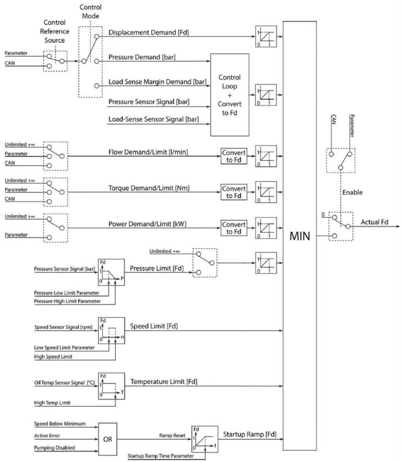
The service control algorithm diagram represents the signals and parameters used to control each service of a DDP.
Note that F_d stands for displacement fraction and represents a normalized displacement from 0 to 1 for a given service.
The + symbol is used to represent that demand/limit is unlimited, but when the signal has been converted to F_d and saturated, only a value of 1 will be passed along.
The MIN block signifies that multiple demands/limits may be active at once, but the lowest F_d (i.e. minimum) is given priority and passed to the pumping algorithm. Since the lowest value is given priority, unlimited demands/limits use values of 1. A value of 0 is not used to turn off a demand/limit since this would be passed to the flow algorithm resulting in no flow from the pump.
Flow, Torque and Power Limits can also be considered "demands" if the primary control mode (e.g. pressure control) is commanding a higher F_d than the limit. In this situation, the limit is being used as the active command. This allows the DPC12 to be used in a flow control setup, for example, even though there is no apparent primary control mode for this.
It may not be desirable to operate on a Torque, Power or Pressure Limit for significant periods of time since these have high gains and can cause system instability. They can however be useful in avoiding excess load on the prime mover and stall conditions.
Control loop diagram
flowchart
graph LR
    A["0"] --> B["Load-Sense Sensor Signal"]
    B --> C["+"]
    D["Pressure Reference Limit Parameter"] --> E["Small P Gain"]
    E --> F["+"]
    G["Pressure Small Gain Parameter"] --> H["Small P Gain"]
    I["Pressure Small Gain Threshold Parameter"] --> H
    J["Pressure Big Gain Parameter"] --> K["Big P Gain"]
    L["Pressure Big Gain Threshold Parameter"] --> K
    M["Pressure Integration Time Parameter"] --> N["1/Ti ∫ dt"]
    O["Pressure Integration Max Displacement Parameter"] --> N
    P["Pressure Integration Min Displacement Parameter"] --> N
    Q["Pressure Sensor Signal"] --> R["+"]
    S["Load-Sense Margin Demand"] --> T["+"]
    U["Pressure Sensor Signal"] --> V["+"]
    W["Control Mode"] --> X["+"]
    Y["Convert to Fd"] --> Z["Output"]
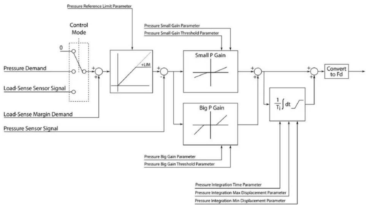
The control loop diagram represents the pressure control loop which is part of the service control algorithm diagram. The pressure control loop requires the signal from the pressure sensor mounted at the outlet of the service. A load-sense pressure signal is required from a pressure sensor in the load-sense resolving network of the service if Load-Sense Mode is used. The proportional gains and integration time are tuned via non-volatile parameters. Contact your Danfoss representative for details on tuning these parameters.
Control operation
Example use cases
Here are some example combinations of control modes and limits:
- Single Service Displacement control by PLUS+1*: Entire pump displacement used for one service, controlled by a displacement command that is saved in a parameter in non-volatile memory. The service is enabled/disabled by another parameter in memory.
- Single Service Displacement control by J1939 with Torque Limit: Entire pump displacement used for one service, controlled by a displacement command that is sent to the DPC12 via J1939 CAN message. A Torque Limit is sent via CAN to limit the maximum torque applied to prime mover from the service. A Pressure Limit is set via two parameters saved in memory. The service is enabled/disabled via CAN message.
- Single Service Pressure control by J1939 with Flow Limit: Entire pump displacement used for one service, controlled by a pressure command that is sent to the DPC12 via J1939 CAN message. A Flow Limit is sent via CAN to limit the maximum flow produced by the service. A Power Limit is set via one parameter saved in memory. The service is enabled/disabled via CAN message.
- Two Service Mixed Displacement/Load Sense control by J1939: Pump displacement used for 2 services. Service 1 has displacement control, torque limit, and enable/disable by CAN messages, as well as pressure limit from a parameter saved in memory. Service 2 has Load Sense control, torque limit, and enable/disable by CAN messages, as well as pressure limit from a parameter saved in memory.
The combinations above are all available from software version 2.7.1 onwards.
Controller interaction
Overview
Interaction with the DPC12 for configuration, tuning commissioning and diagnostics is achieved with the PLUS+1*Service Tool and the PLUS+1*Diagnostic (P1D) file that matches the controller software version.
Communication occurs over the CAN bus and a CAN gateway such as the Danfoss CG150 is required. The diagnostic file allows parameter changes which select the control mode, limits, tuning gains, and other features. These parameters are saved in non-volatile memory. There are also pages to interact with Commissioning Mode and to see past and active Errors.
PLUS+1\*CAN/USB gateway
Communication between the DPC12 and a personal computer (PC) on software uploads, downloads, Service Tool, and Diagnostic Page interaction is accomplished using the system's CAN bus.
The PLUS+1* CG150-2 CAN/USB gateway provides the communication interface between the system CAN bus and a PC USB port. When connected to a PC, the gateway acts as a USB slave. In this configuration, all required electrical power is supplied to the gateway by the upstream PC host. No other power source is required.
Refer to the PLUS+1® Guide Software User Manual (document number AQ152886483724) for gateway setup information. Refer to the CG150-2 CAN/USB Gateway Data Sheet (document number AI152986480800) for electrical specifications and connector pin details.
Other CAN gateways can be used. Please contact your Danfoss representative for more information.
Configuration and tuning
Configuring the DPC12 involves selecting the desired CAN Node Address, control mode, and limits using the diagnostic file associated with the software version.
Tuning is required for pressure and load sensing control modes. Gain parameters are set to achieve different pump response behavior in the application system. These parameters are typically set by system engineers during pump commissioning in the system. For further information and help with tuning, contact your Danfoss representative.
Control operation
Identical application systems, such as machines of the same make and model, can use the same configuration and tuning parameters. Use the DPC12 All Params page in the diagnostic file to export parameters from one controller and import them to another.
Commissioning mode
Commissioning mode is used during initial DDP installation to incrementally test the functionality of the solenoids and valves, help with air removal, and to aid in troubleshooting of the system. In this mode, some limits and errors are ignored to enable these activities.
To enter commissioning mode and access system functions, follow these steps:
- Go to the DPC12 Commissioning page of the diagnostic file and press the Enter Commissioning Mode button.
The device is now in commissioning mode.
- Choose the appropriate commissioning action types from the Commissioning Action Type parameter dialog.
Available parameters are as follows:
Fire
Actuates the specified coil as soon as possible. Use when the shaft is not spinning to verify wiring.
Pump
Actuates the specified coil at the correct shaft position to enable the pumping unit (one piston and its valve) to pump a full stroke 1 or 100 times depending on the Action Type chosen. Use while shaft is spinning to verify pumping or create small amounts of flow for leak testing.
Raw
Displacement
Actuates coils as necessary to achieve the desired percentage of displacement. Use to check that correct flow rate is produced or to allow limited functionality of open center hydraulic circuits.
After the action type is chosen, action type specific interfaces will be available on screen.
To exit Commissioning mode, press the Exit Commissioning Mode button, then follow the prompts. For more information on Commissioning Mode parameters and interaction, contact your Danfoss representative.
Diagnostics and errors
The DPC12 logs active and previously active errors. These errors are broadcast over CAN using standard Diagnostic Messages such as DM1 and DM2. Errors can also be accessed through the DPC12 Errors page of the diagnostic file.
There are four error severity levels: INFO, WARNING, CRITICAL and SEVERE. INFO level errors will not cause the DPC12 to transition to ERROR or ERROR_HOLD states. WARNING and CRITICAL level errors will cause the DPC12 to transition to ERROR state when active, but once they are all inactive, the DPC12 will transition to ERROR_HOLD. Once SEVERE level errors are active, they cause the DPC12 to transition to ERROR state, but will not cause it to change to ERROR_HOLD even if they become inactive. SEVERE level errors require the DPC12 to be power cycled.
For more information on error code meanings and CAN message descriptions, see the Software Manual or contact your Danfoss representative.
Model code
DDP model code
The example model code below and the following section describes how to identify parts of the model code and availability of certain part options.
Model code sections
| A B C D E | F G H I J K L M | |||||||||||
| DD P 096 | SHNN R C | ANN CP 1A | AA BA B N | NNN (continued | below) | |||||||
| N | O | P | Q | R | S | T | U | V | W | X | Y |
| NN | NNNN | NN | B | NNN | A1 | NN | B1 | A1 | AA | 02071 | 00012 |
Model code breakdown
A Series
B Pump
C Displacement
D Product type
E Rotation
F Mounting flange
G Input shaft spline and auxiliary shaft spline
H Auxiliary mounting flange (through-drive flange)
I Endcap
J Sensors and harness
K Common parts
L Tandem pump mounting flange
M Tandem pump input shaft spline and auxiliary shaft spline
N Tandem pump auxiliary mounting flange
0 Tandem pump endcap
P Tandem pump sensors and harness
Q Tandem pump common parts
R Accessory block
S Paint and nametag
T Special hardware or features
U Electronic hardware
V Electronic hardware nametag
W Software build
X Software version
Y Software parameter set
Model code
DDP part options
Below is a list of the available configuration options for the DDP. Note that not all combinations are possible.
The tandem section of the model code is not presented below.
The stand-alone letter in the title corresponds with model code location. Please refer to DDP model code on page 26 for entire model code breakdown.
C; Displacement
| Code Description | |
| 096 96 cm | ^3 /rev [5.86 in ^3 /rev] maximum displacement |
D; Product type
| SHNN Single pump for | high-power applications |
E; Rotation
| R Clockwise rotation [CW] |
| L Counterclockwise rotation [CCW] |
F; Mounting flange
| C SAE C 4-bolt |
G; Input shaft spline and auxiliary shaft spline
| ANN 23T input; no aux | liary shaft |
| A09* 23T input; 9T aux | liary coupling |
| A11* 23T input; 11T auxiliary coupling | |
| A13* 23T input; 13T auxiliary coupling | |
| A15* 23T input; 15T auxiliary coupling | |
| A14* 23T input; 14T auxiliary coupling | |
| A17* 23T input; 17T auxiliary coupling | |
H; Auxiliary mounting flange (through-drive shaft)
| CP Cover plate (no auxiliary flange) |
| AA* 2-bolt SAE A auxiliary mounting flange |
| BA* 2-bolt SAE B auxiliary mounting flange |
| CA* 4-bolt SAE C auxiliary mounting flange |
* On request.
I; Endcap (inlet and outlet ports)
| 1AAA | Single-outlet endcap:Inlet port S: DN 51 ISO 6162-1; M12 x 1.75Outlet port P: DN 25 ISO 6162-2; M12 x 1.75 |
| 3BAA | Multi-outlet endcap:Inlet port S: DN 51 ISO 6162-1; M12 x 1.75Outlet port P1: DN 19 ISO 6162-2; M10 x 1.5Outlet port P2: DN 13 ISO 6162-2; M8 x 1.25Outlet port P4: DN 13 ISO 6162-2; M8 x 1.25 |
Model code
J; Sensors and harness
| Code Description | |
| BA For a 1-service pump (speed/temperature sensor W; pressure sensor M) | |
| BG For a 2-service pump (speed/temperature sensor W; pressure sensors M1 & M4) | |
| BE For a 3-service pump (speed/temperature sensor W; pressure sensors M1, M2 & M4) | |
K; Common parts
| B |
R; Accessory block
| NNN None |
S; Paint and pump nametag
| A1 Black paint; Danfos$ standard tag |
T; Special hardware
| NN None |
U; Electronic hardware
| B1 DPC12 pump controller |
V; Electronic hardware nametag
| A1 Danfoss standard tag |
W; Software build
| AA For 1-service operation with DDP096 single |
| AB For 2-service operation with DDP096 single |
| AC For 3-service operation with DDP096 single |
X; Software version
| 02102 2.10.2 software version |
Mechanical installation
Pump transport and handling
Due to the electrically actuated nature of each valve in the pump and the presence of multiple sensors, there are wires attached to the outside of the pump body and to each coil, making the pump susceptible to mechanical impacts.
Any damage to the wires, connectors, sensors, or coils may cause the pump not to function correctly. Avoid all impacts while transporting the pump. Contact your Danfoss representative if there is any damage to any of the wires, sensors, or coils on the pump.
Do not directly or indirectly strike the coupling or driveshaft of the pump as this may cause internal damage.
Do not drop the pump. If dropped, do not use the pump and contact your Danfoss representative.
There are three handling brackets on DDP096 pumps. One bracket is on one side of the housing (pumplet 1) and the two other brackets are opposite of each other on the endcap at the rear of the pump. For each lifting bracket the weight limit is 70 kg.
It is recommended to lift a single pump by attaching hooks to the two handling brackets on the endcap and using the bracket on the housing for orientation. It is also possible to lift a single pump by attaching a hook on the housing handling bracket and using the endcap brackets for orientation.
Handling brackets and orientation
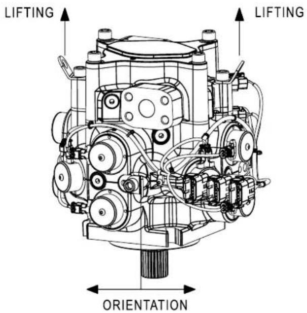
Handling brackets are not aligned with the center of gravity. Some swiveling should be expected when handling.
Alternatively, the blind tapped holes M12 x 16 mm (non-standard depth) in the pump housing can be used for lifting with customer lifting equipment. Standard lifting fittings will not fully engage without using washers/spacers. There are four tapped holes in total around the pump – one for each pumplet (located adjacent to the coils of bank A and C and opposite to the bleed port). For more information, see Common dimensions on page 35. If needed, the handling bracket on the housing (pumplet 1) can be repositioned on one of these tapped holes and torqued to 60 N.m.
Make certain all lifting gear is rated for the load to be applied and that standard precautions and best practices are used while lifting the pump.
Mechanical installation
Caution
The handling brackets are not rated for any duty other than lifting the pump and the factory supplied wires and sensors. The brackets are not rated to lift any hoses or pipes that may be attached to the pump during installation. Handling brackets on the endcap must not be removed under any circumstance.
If the pump needs to be temporarily stored outside the application or the provided packaging, we recommend resting the pump vertically (shaft pointing downwards) on the SAE C flange. Stable spacers are required to avoid contact with the input shaft. It is also possible to rest the pump horizontally, using cast features of the pump as supports. Suitable spacers must be used to avoid any contact with the coils, sensors and wiring harnesses of the pump.
Caution
Ensure no load is applied to coils, sensors, or wiring when placing the pump on a surface for storage as these may become damaged.
Storage
The packaging supplied with the pump provides a stable storage method with the shaft pointing downwards and held in place by the box's lid to avoid any movement during transport. The controller and other accessories provided will be in a different compartment of the box. All elements will be protected against corrosion and reasonable handling shocks. This packaging is suitable for storage.
The storage area must be free from corrosive materials and gasses. The storage area must be dry (5-60% relative humidity, non-condensing). The ideal temperature for storage is between 5°C and 40°C.
After removing a pump from storage, check over the unit for visible damage to any of the wiring or sensors.
If the pump must be stored for long periods or in a humid environment (relative humidity >60%), seal the parts in airtight bags with desiccant sachets and use VCI materials to protect the hydraulic items. Store the controller in an antistatic bag, ideally in the same packaging as shipped.
Installation requirements
The installation locations and position of the pump must be as described in this document. Adhere to all limits specified in the DDP096 pump specifications section regarding pressure, temperature, viscosity and cleanliness of the hydraulic fluid. Other configurations are possible; please contact your Danfoss representative for direction.
Pump arrangement
It is recommended to install the pump in a below-oil level and horizontal or near-horizontal shaft position. This is the location the pump is installed outside of the tank and below the minimum level of fluid in the tank or inside the tank with sufficient fluid above. Other arrangements are possible, for which care must be taken to bleed the pump case.
Pump shaft coupling
At low displacement ( F_d < 0.2 ), Digital Displacement ^* pumps create torque oscillations with torque reversals increasing the risk of fretting corrosion at the input shaft interface. It is required to take great care in shaft coupling interface to increase operating life.
Flooded input shaft installation provides good corrosion protection. For dry shaft installation, a greased clamped coupling is recommended. If clamped coupling is not possible, care must be taken to reduce the risk of shaft interface damage. Application of specific anti-corrosion grease is required in this case and should be regularly maintained. For information on lubrication of spline shafts, refer to Lubrication of Spline Shafts – Technical Specifications.
Mechanical installation
Excessive misalignment can cause premature wear. Refer to coupling manufacturer specifications for allowable misalignment. Hardness of the mating spline must be at least 55 Rc and have full spline depth.
Understanding and minimizing system noise
A range of countermeasures has been developed to manage noise, vibration, and harshness. Standard best practices such as increasing hydraulic compliance or decoupling the hydraulic circuit from the application chassis can have a big impact.
The following suggestions can help minimize noise and vibration in applications:
- Increase system compliance by installing longer or larger hoses, thermoplastic hoses, accumulators, or more oil volume.
- Use flexible hoses alongside steel plumbing.
• If possible, optimize system line position to minimize noise.
• If adding additional support, use rubber mounts.
• Test for resonances in the operating range; if possible, avoid these operating conditions.
Some applications or actuators are more susceptible to vibration than others. Systems with physical characteristics such as low actuator inertia or very high hydraulic stiffness at low flow rates will need to be considered more carefully. Contact your Danfoss representative for more support.
Special control methods are recommended for systems with multiple DDP units connected in parallel to the same hydraulic load. Consult your Danfoss representative for advice.
Air removal
Air within the pump must be removed to ensure proper operation.
Trapped air in the inlet passages can impair valve function, causing zero output flow from the affected pistons. The pump is unable to pump the air out of the piston chamber as soon as discharge pressure reaches a few bars; air must be removed from the case before starting to pump.
Significant reduction in pump lifetime will occur if the pump spins dry.
Air must be bled from the pump body at commissioning, when changing oil in the system, and after long periods without running or maintenance.
To check that there is no air left in the pump, use the PLUS+1° Service Tool and the DDP diagnostic file (P1D) to enter Commissioning mode and follow the commissioning procedure (see Commissioning mode on page 25).
There are several options for removing air from the pump case.
Removing air by gravity
If the pump is located under the oil level with a direct inlet hose connection (no swan neck connection above oil level), use one of the four radial bleed ports (L1 to L4) in the pump body.
The ports (with plugs installed) are indicated in Common dimensions on page 35 and can be used for air removal or flushing.
- Connect the inlet hose and fill the tank.
- Remove the topmost bleed port plug to allow trapped air to escape.
Allowing air to escape through the bleed port will also allow oil to flow out of the case. Loosen the plug gradually to avoid spurting oil. - Replace the plug when there is a steady stream of oil draining from the case (no air bubbles).
- Torque the plug to 35 N·m ± 10%.
Removing air with an auxiliary pump
If the pump is located above the oil level and/or the inlet hose goes over the oil level, loosening the bleed port plugs will not allow air removal. It is possible to connect the topmost bleed port of the pump to a tee connector at the inlet of an auxiliary pump, such as a fixed displacement pump commonly used for
Mechanical installation
brakes, fans or other auxiliary functions. This method can be used to remove build-up of air if the pump is installed near the tank oil level or if during operation the pump is at or above the tank oil level (such as in a vehicle on a slope).
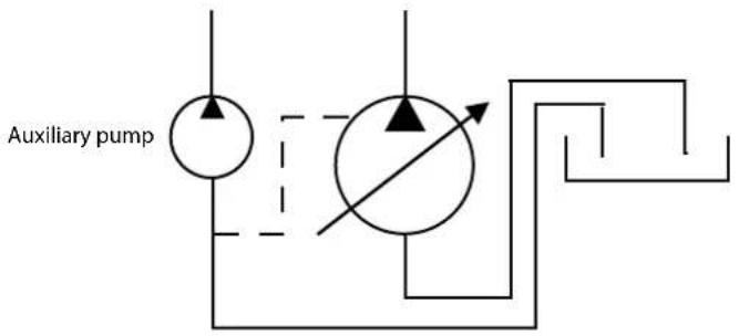
It is important that the pump case is as full as possible before spinning the shaft.
If the pump case is not at least half full, there is a risk of damaging the bearings and other internal components.
Use moderate shaft speed (<1000 rpm) and check that the pump is operating correctly within half a minute.
Check auxiliary pump priming requirements.
Removing air through the DDP outlet port
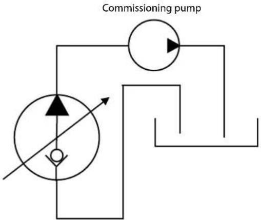
Air can be suctioned out of the DDP outlet port by temporarily connecting the inlet of a commissioning pump to the outlet of the DDP. The outlet check valves will open and allow oil to fill the crankcase and all piston chambers. This air removal process will remove most of the air, but some small air pockets may remain in the case. This method can then leave time to connect the high-pressure system hose to the DDP outlet port.
In the case of a multi-service system, connect the commissioning pump to the service connected to the topmost pumplet of the DDP. Refer to Multi-outlet pump on page 6 for more information on pumplets and services.
flowchart
graph TD
    A["Commissioning pump"] --> B["Directional Valve"]
    B --> C["Control Valve"]
    C --> D["Flow Path"]
    D --> E["Return Line"]
    style A fill:#f9f,stroke:#333
    style E fill:#bbf,stroke:#333
Extreme care should be taken with this method to ensure that oil is properly drawn through the pump housing.
Ensure that the shaft is not spinning while the discharge port is not connected to the final hydraulic circuit.
If the shaft is spinning, the DDP could pump and the outlet line could over-pressurize. Over-pressurizing the outlet line creates a risk of injury and damage.
Mechanical installation
Removing air by submersion
If the pump is fully submerged in the hydraulic tank, the bleed port plugs can be removed completely from all four locations in the pump body. The air will automatically leave the case.
Flushing
The DDP does not have a case drain port to connect to the tank, as the fluid volume within the pump body is connected to the inlet. Any fluid that leaks out of the piston chambers is drawn back into the inlet. In normal operation, oil flowing through the pump from the inlet cools the moving parts when pumping.
For applications involving prolonged idle operation with close to no flow rate (less than 5 L/min for more than 5 minutes), the case must be flushed with cooled and filtered oil to prevent fluid stagnation and local high temperature build-up in the crankcase.
Bleed ports (from L1 to L4) can be used for flushing purposes. Flow should ideally be pushed to the crankcase, but can also be through suction.
When designing a flushing circuit, adhere to the maximum pressure limit of the crankcase (refer to the maximum inlet pressure value in DDP general specifications on page 11) and be aware of any filter back-flushing potential on suction lines. Any fluid pushed into the crankcase may reverse the flow in the inlet line and back-flush to the tank.
The DPC12 controller will detect and report the over-temperature condition. It can prevent pump operation when crankcase temperature exceeds the error limit. This error limit does not protect the pump from overheating since the pump controller cannot prevent shaft rotation. Specific software features can be enabled depending on application.
Filtration
Fluid entering the pump inlet must be free of contaminants to prevent damage and premature wear to the pump. Digital Displacement ^® pumps require system filtration capable of maintaining fluid cleanliness. Refer to the DDP general specifications on page 11.
Suction line filtration is not recommended. This type of filtration can cause high inlet vacuum which limits the pump operating speed and can reduce its operating life. Suction strainers can have similar effects. If you plan to use a suction strainer, discuss it with your Danfoss representative.
Return line filtration is the preferred method for open circuit systems. Consider these factors when selecting a system filter:
- Cleanliness specifications
• Contaminant ingression rates - Flow capacity
• Desired maintenance interval
Each system is unique, and only a thorough testing and evaluation program can fully validate the filtration system. For more information, see Design Guidelines for Hydraulic Fluid Cleanliness (document BC152886482150).
Use hydraulic fluid free of air and water. Excess bubbles or moisture can cause damage to the pump's internal components.
Do not use any cleaning material that may deposit lint or other debris in the hydraulic system. Do not use PTFE tapes to seal fittings.
After circuit changes, flush the circuit without the DDP if possible.
Controller mounting
Ensure that the DPC12 is positioned so water and moisture drain away from the connectors. Provide a drip loop in the harness (whilst ensuring any bends near the connector do not cause the sealing face of the Deutsch connector to lose contact with the fitted wire). Provide strain relief for mating connector
Mechanical installation
wires. If the product is likely to be cleaned using high pressure washing, connector shields must be installed to prevent the possibility of a direct high-pressure stream.
Caution
Operating the DPC12 over the maximum temperature value can cause the controller to overheat and disable pumping. Refer to General ratings on page 14 for acceptable ambient temperatures.
Fasteners for DPC12 controller only
Recommended outer diameter (OD)
6 mm [1/4 inch]
Mechanical installation
Pump dimensions
Common dimensions
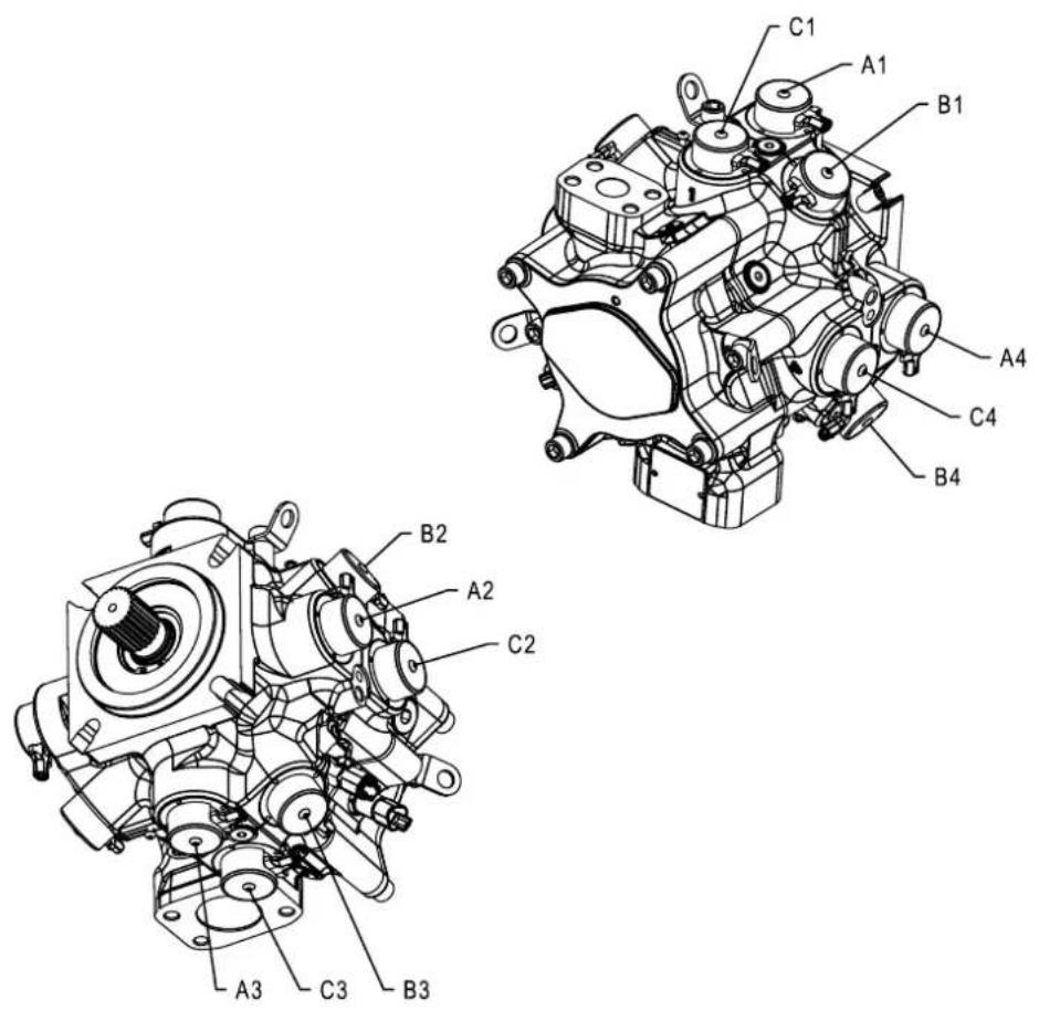
| Label Name Description Coil harness connection | ||
| A1 Coil A1 Coil 1 from bank A Coil harness “A” | ||
| A2 Coil A2 Coil 2 from bank A Coil harness “A” | ||
| A3 Coil A3 Coil 3 from bank A Coil harness “B” | ||
| A4 Coil A4 Coil 4 from bank A Coil harness “B” | ||
| B1 Coil B1 Coil 1 from bank B Coil harness “A” | ||
| B2 Coil B2 Coil 2 from bank B Coil harness “A” | ||
| B3 Coil B3 Coil 3 from bank B Coil harness “B” | ||
| B4 Coil B4 Coil 4 from bank B Coil harness “B” | ||
| C1 Coil C1 Coil 1 from bank C Coil harness “A” | ||
| C2 Coil C2 Coil 2 from bank C Coil harness “A” | ||
| C3 Coil C3 Coil 3 from bank C Coil harness “B” | ||
| C4 Coil C4 Coil 4 from bank C Coil harness “B” |
Common dimensions are made on drawings from the single-outlet pump.
Mechanical installation
Shaft end view dimensions
Dimensions in mm*
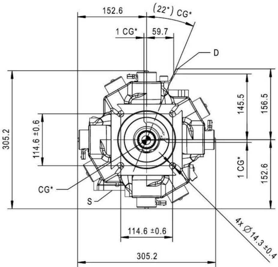
* Unique to single-outlet pumps
Mechanical installation
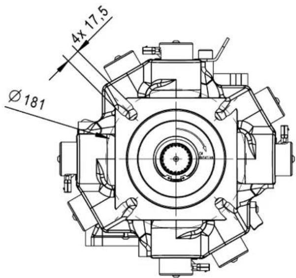
Flange dimensions
Dimensions in mm
Mechanical installation
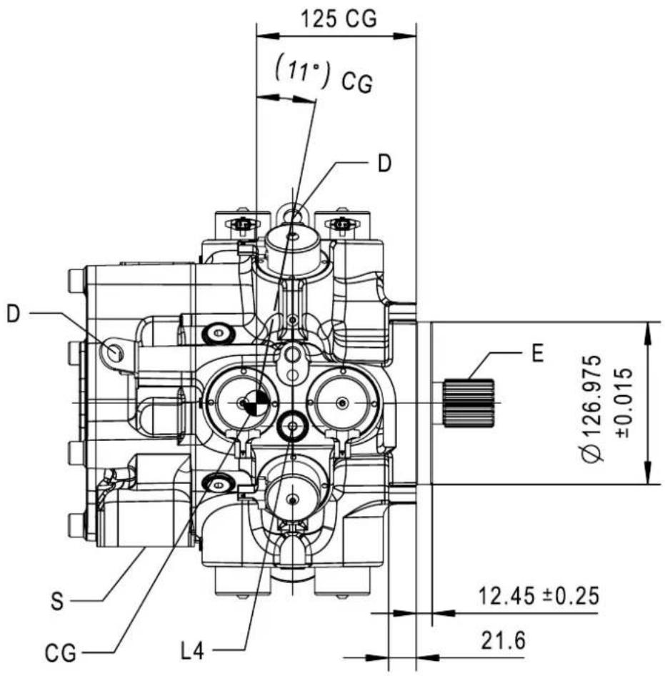
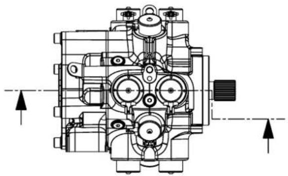
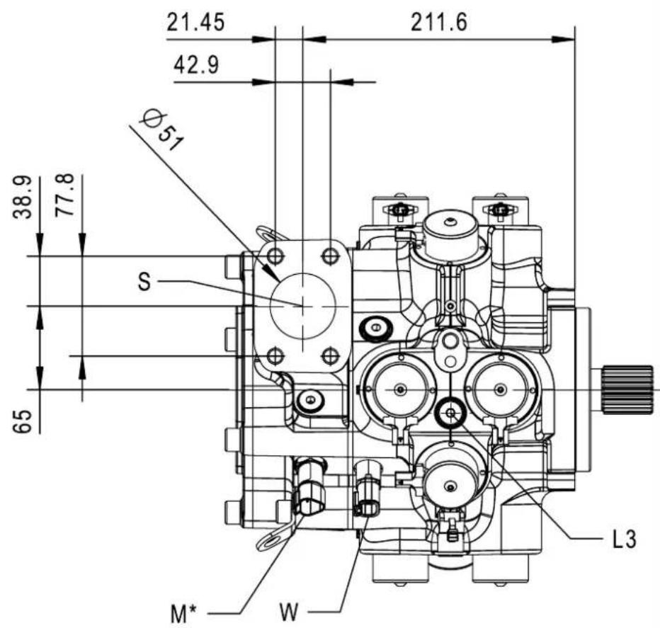
Side view dimensions
Shaft oriented right; dimensions in mm
Mechanical installation
Shaft oriented right; dimensions in mm
natural_image
Technical line drawing of a mechanical assembly with no visible text or symbolsMechanical installation
Shaft oriented left; dimensions in mm
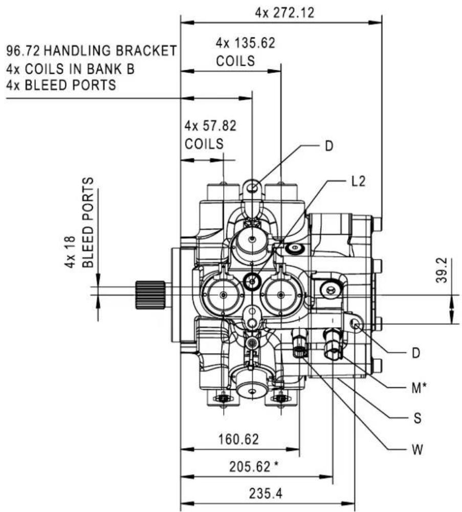
* Unique to single-outlet pumps
Mechanical installation
Top view dimensions
Dimensions in mm
* Unique to single-outlet pumps
Mechanical installation
Rear view dimensions
Dimensions in mm
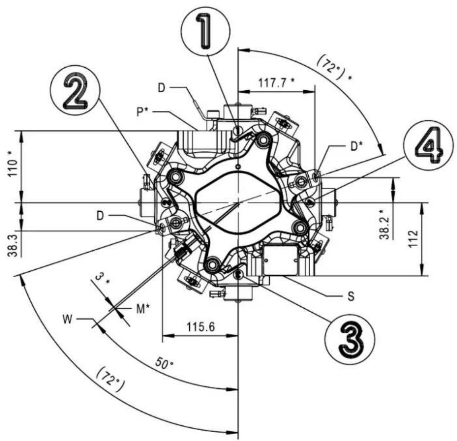
* Unique to single-outlet pumps
Mechanical installation
Single-outlet pump dimensions
Dimensions in mm
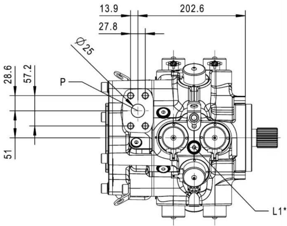
* Common
Label information
| Label Description | |
| P Pressure port: | Split flange bossDN 25 (∅25) ISO 6162-2M12 x 1.75; 24 mm full min threadPaint free |
| S Suction port: | Split flange bossDN 51 (∅ 51) ISO 6162-1M12 x 1.75; 19 mm full min thread (non-standard depth)Paint free |
| L1, L2, L3, L4 Bleed ports: | M14 x 1.5 port ISO 6149-1Torque to 35 N·m ± 10% |
| D Handling brackets: 1 | 4.2 mm [0.56 in] hole diameter |
| E Shaft spline (see Shaft spline data below) | |
| W Speed/temperature | sensor; DEUTSCH DTM04-4 connector |
| M Pressure sensor M; D | EUTSCH DT04-3 connector |
| CG Approximate center | of gravity for single-outlet pump |
Mechanical installation
Shaft spline data
| Number of teeth | 23 |
| Pitch fraction | 16/32 |
| Pressure angle | 30^ |
| Pitch diameter | 36.513 mm [1.438 in] |
| Major diameter | 37.59 ± 0.08 [1.48 in] |
| Type of fit | Fillet root side |
| Specification | ANSI B92.1b-1996 class 6e |
Mechanical installation
Multi-outlet pump dimensions
For other dimensions, see Common dimensions on page 35 and Single-outlet pump dimensions on page 43.
Dimensions in mm
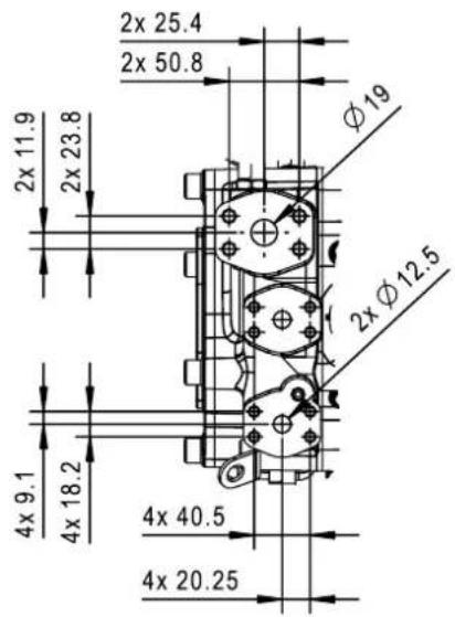
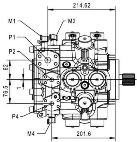
Mechanical installation
Multi-outlet pump side view dimensions
Shaft oriented right; dimensions in mm
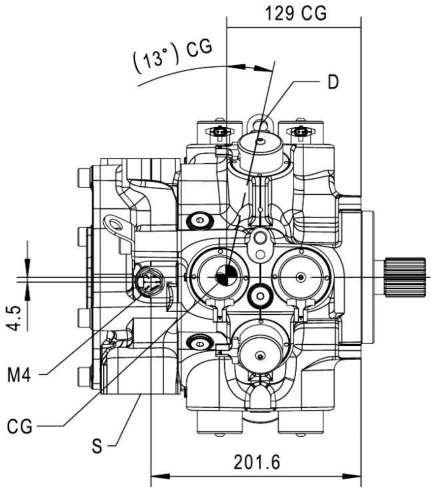
Mechanical installation
Shaft oriented left; dimensions in mm
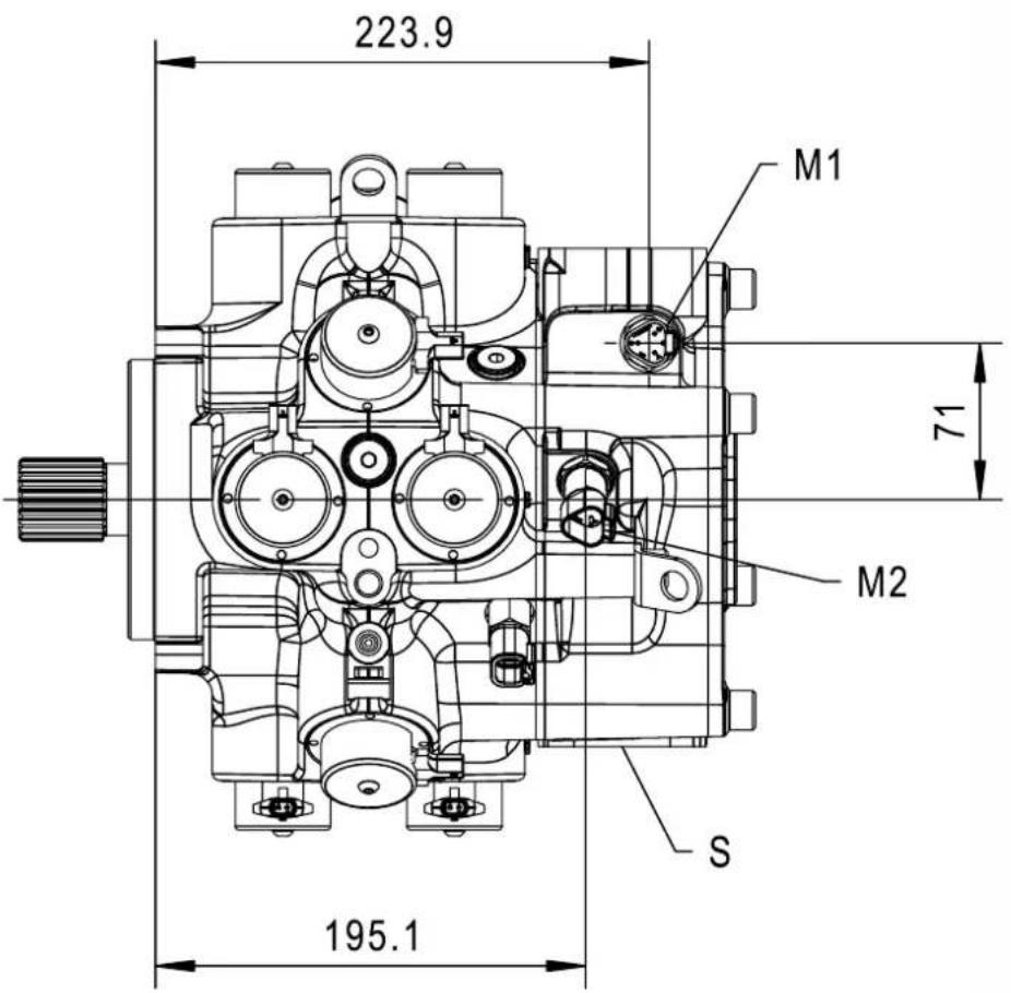
Mechanical installation
Multi-outlet pump rear view dimensions
Dimensions in mm
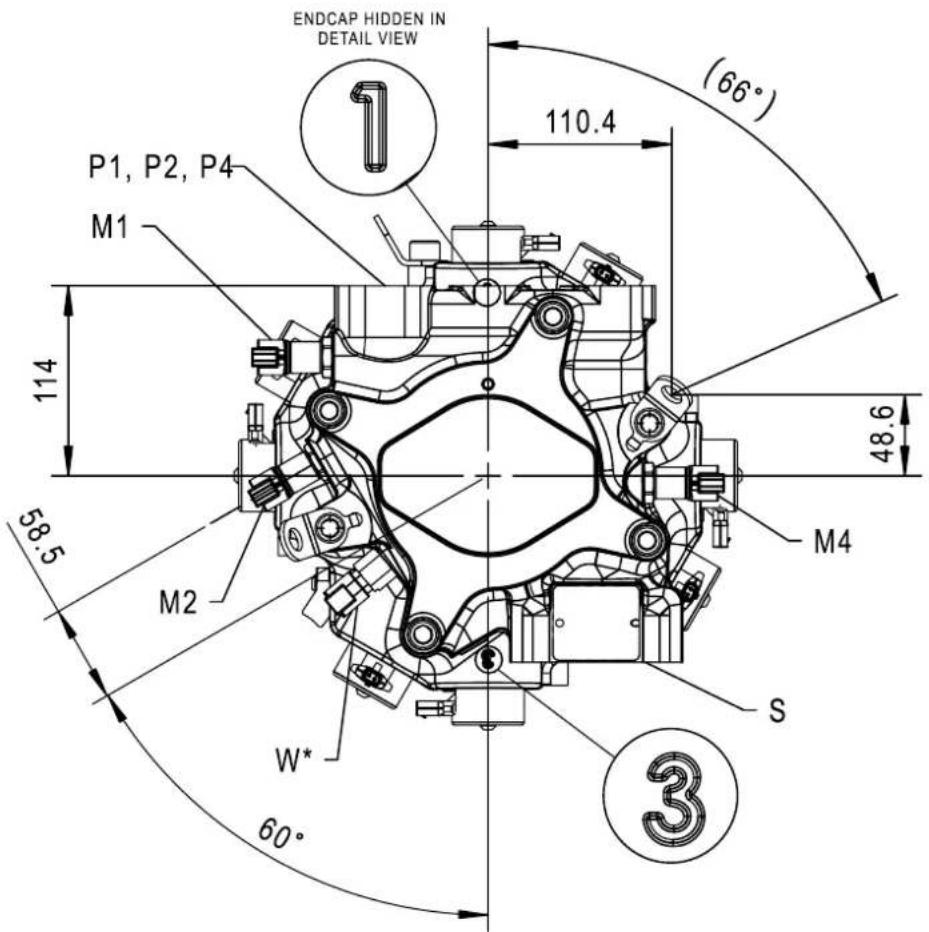
*Common
Label information
| Label Description | |
| P1 Pressure port 1: | Split flange bossDN 19 (∅19) ISO 6162-2M10 x 1.5; 19 mm full min threadPaint free |
| P2 Pressure port 2: | Split flange bossDN 13 (∅12.5) ISO 6162-2M8 x 1.25; 16 mm full min threadPaint free |
Mechanical installation
Label information (continued)
| Label Description | |
| P4 Pressure port 4: | Split flange bossDN 13 (∅12.5) ISO 6162-2M8 x 1.25; 16 mm full min threadPaint free |
| M1 Pressure sensor M1; | DEUTSCH DT04-3 connector |
| M2 Pressure sensor M2; | DEUTSCH DT04-3 connector |
| M4 Pressure sensor M4; | DEUTSCH DT04-3 connector |
Please contact your Danfoss representative for specific dimension drawings or to discuss ganging manifold designs.
Mechanical installation
Controller dimensions
Dimensions in mm
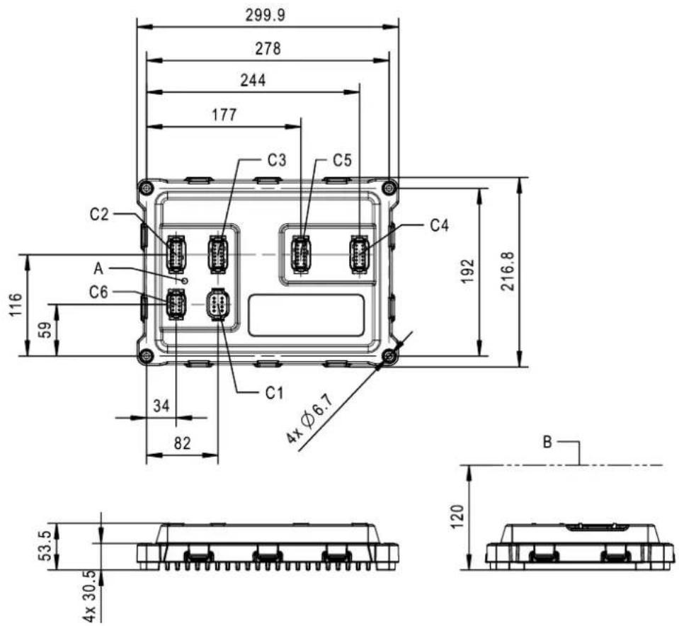
Label information
| Label Description | |
| A Controller LED - refer to section LED Messages | |
| B Minimum clearance to install the mating receptacles | |
| C1^x | Power connection |
| C2^x | System connection |
| C3^x | Sensor connection |
| C4^x | Coil harness “A” connection |
| C5^x | Coil harness “B” connection |
| C6^x | Communication connection |
Receptacles for the controller wiring harness. For more information, see Connectors on page 55.
Electrical installation
Installation requirements
Wiring overview
The OEM of the machine or vehicle is responsible for wiring the DDP096 and DPC12 into the application. The DDP096 comes with a wiring harness that must be connected to the DPC12 via the pump-to-controller wiring harness. The DPC12 must also be connected to a power supply and, if applicable, a CAN bus.
For more information about the DPC12 connections, see Connectors on page 55.
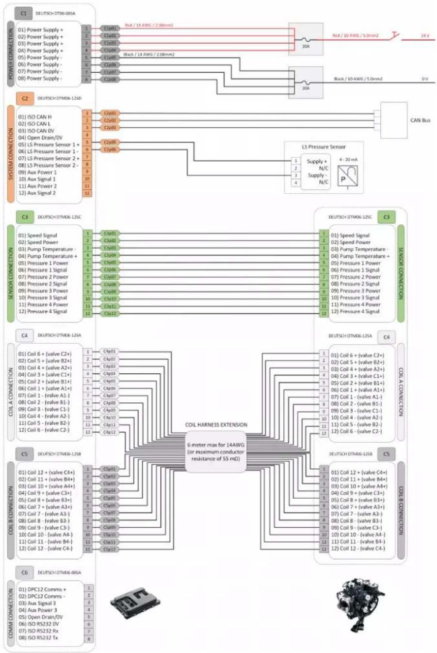
flowchart
graph TD
    subgraph Power Connections
        A1["01"] --> A2["Power Supply +"]
        A2 --> A3["02"] --> A4["Power Supply +"]
        A4 --> A5["03"] --> A6["Power Supply +"]
        A6 --> A7["04"] --> A8["Power Supply +"]
        A8 --> A9["05"] --> A10["Power Supply -"]
        A10 --> A11["06"] --> A12["Power Supply -"]
        A12 --> A13["07"] --> A14["Power Supply -"]
        A14 --> A15["08"] --> A16["Power Supply -"]
    end

    subgraph System Connections
        B1["01"] --> B2["ISO CAN H"]
        B2 --> B3["ISO CAN L"]
        B3 --> B4["ISO CAN DV"]
        B4 --> B5["Open Drain/0V"]
        B5 --> B6["LS Pressure Sensor 1 +"]
        B6 --> B7["LS Pressure Sensor 2 +"]
        B7 --> B8["LS Pressure Sensor 2 -"]
        B8 --> B9["Aux Power 1"]
        B9 --> B10["Aux Signal 1"]
        B10 --> B11["Aux Power 2"]
        B11 --> B12["Aux Signal 2"]
    end

    subgraph Sensor Connections
        C1["01"] --> C2["DEUTSCH OTM06-08SA"]
        C2 --> C3["Red / 14 AWG / 2.08mm2"]
        C3 --> C4["30A"]
        C4 --> C5["Black / 14 AWG / 2.08mm2"]
        C5 --> C6["30A"]
        C6 --> C7["CAN Bus"]
    end

    subgraph Coil Connections
        D1["01"] --> D2["DEUTSCH OTM06-12SC"]
        D2 --> D3["CSp01"]
        D3 --> D4["CSp02"]
        D4 --> D5["CSp03"]
        D5 --> D6["CSp04"]
        D6 --> D7["CSp05"]
        D7 --> D8["CSp06"]
        D8 --> D9["CSp07"]
        D9 --> D10["CSp10"]
        D10 --> D11["CSp11"]
        D11 --> D12["CSp12"]
    end

    subgraph Coil Harness Extension
        E1["COIL HARNESS EXTENSION"]
        E1 --> E2["6 meter max for 14AWG (or maximum conductor resistance of 55 mΩ)"]
        E2 --> E3["DEUTSCH OTM06-12SA"]
        E3 --> E4["C4"]
        E4 --> E5["C5"]
    end

    subgraph Coil Connection
        F1["COIL A CONNECTION"]
        F2["COIL B CONNECTION"]
        F3["COMM CONNECTION"]

    end
Electrical installation
All mating connectors must be supplied by the OEM and any unused pin positions must have sealing plugs installed to prevent water ingression.
DDP096 connectors (C3, C4 and C5) must be connected to the DPC12 connectors of the same label (C3, C4 and C5) via a pump-to-controller wiring harness.
The pin numbers for each connector should correspond to each connection (pin 1 goes with pin 1, etc.).
For more information on wiring the power connector, refer to DPC12 input power supply on page 13 and Machine wiring guidelines on page 52.
Machine wiring guidelines
Follow these guidelines when wiring the pump and controller.
Caution
Do not handle the controller in high static environments without appropriate precautions.
• Unused pin positions in the DEUTSCH connectors must have sealing plugs installed to prevent water ingression
- Protect wires from mechanical abuse with durable sheathing or by running wires through flexible conduit tubing
• Provide strain relief for all wires
- Use wire harness anchors, especially for the DEUTSCH connectors, that will allow wires to float with respect to the machine rather than rigid anchors
- Avoid hot surfaces; if hot surfaces cannot be avoided, use cables rated for high temperatures: 85°C (185°F) wire with abrasion-resistant insulation and 105°C (221°F) wire near hot surfaces are recommended
- Apply dielectric grease in connectors if used in a harsh environment
• Use a wire size appropriate for the controller; for details on pin sizes, refer to Connectors on page 55
- Separate high current wires such as solenoids, lights, alternators or fuel pumps from sensor and other noise-sensitive input wires
- Run wires along the inside of, or close to, metal machine surfaces where possible to simulate a shield to minimize the effects of EMI/RFI radiation
- Do not run wires near sharp metal corners; consider running wires through a grommet when rounding a corner
- Avoid running wires near moving or vibrating components
- Avoid long, unsupported wire spans
• Ground electronic controllers to a dedicated conductor of sufficient size that is connected to the battery (-)
- Power the sensors and valve drive circuits by their dedicated wired power sources and ground returns
- To reduce resistive power losses, the power supply cable to the DPC12 controller should use the maximum wire gauge the connector can accept (2 mm ^2 or 14 AWG) and be as short as possible; the maximum length should not be longer than 10 meters, contact your Danfoss representative otherwise
Caution
Avoid accidentally connecting incorrect pins to supply power. Significant current driven back through an incorrect pin may damage the controller. Damage to the unit voids the warranty.
Electrical installation
Machine welding guidelines
Follow these guidelines when welding on a machine equipped with electronic components.
- Turn off the engine.
- Remove electronic components from the machine before any arc welding.
- Disconnect the negative battery cable from the battery.
Caution
Do not use electrical components to ground the welder.
- Clamp the ground cable for the welder to the component that will be welded as close as possible to the weld.
Caution
Do not weld near the DDP096, DPC12 or their wire harnesses.
High voltage from power and signal cables may cause fire or electrical shock and cause an explosion if flammable gasses or chemicals are present.
Disconnect all power and signal cables connected to the electronic component and remove the DPC12 before performing any electrical welding on a machine.
CAN bus installation
CAN wires must be twisted pairs with one twist approximately every 100 mm (4 in).
Total bus impedance should be 60 Ω. While CAN pins are tolerant of +/-36V, CAN may only be expected to function in the standard CAN common mode range of +12V/-7V. If using shielded cable, be sure to ground the shield appropriately. CAN 0V must be connected to suitable reference in order for CAN to work.
Each end of the main backbone of the CAN bus must be terminated with an appropriate resistance to provide correct termination of the CAN_H and CAN_L conductors. This termination resistance should be connected between the CAN_H and CAN_L conductors.
System diagnostic connector
A diagnostic connector installed on systems using the DPC12 is recommended. The connector should be located in the operator's cabin or in the area where system operations are controlled and are easily accessible.
Communication (software uploads, downloads, service, and diagnostic tool interaction) between DPC12 and personal computers is accomplished over the system CAN network. The diagnostic connector should tee into the system CAN bus and have the following elements:
CAN+
CAN-
• CAN shield
Fuses
Check the Fuses on page 13 for fuse requirements and recommendations.
Ensure separate fuses for the coil and logic power supplies are used.
Grounding
Proper operation of any electronic control system requires that all control modules including displays, microcontrollers and expansion modules be connected to a common ground. A dedicated ground wire of appropriate size connected to the machine battery is recommended.
The DPC12 baseplate must be earthed through its mounting fasteners. All DPC12 ground pins are internally connected and should use the same wire gauge.
Electrical installation
Hot plugging
Shut off machine power when connecting the DPC12 to mating connectors.
Electrical installation
Connectors
The DDP096 and DPC12 use DEUTSCH connectors.
DEUTSCH mating connector part information
Crimp tool
| Tool 12 pin D | TM 8 pin DTM 8 pin DT | ||
| Solid HDT-48-00 (12 to 24 AWG) HDT-48-00 (12 to 24 AWG) HDT-48-00 (12 to 24 AWG) | |||
| Stamped DTT-16-00 (16 AWG) DTT-20-00 (16 AWG) DTT-16-00 (16 AWG) | |||
Contacts
| Description 12 pin DTM 8 pin DTM 8 pin DT | |||
| Solid size 20 contacts | 0462-201-20141 (20 AWG Nickel)0462-201-2031 (20 AWG Gold)0462-005-20141 (16 to 18 AWG Nickel)0462-005-2031 (16 to 18 AWG Gold) | 0462-201-20141 (20 AWG Nickel)0462-201-2031 (20 AWG Gold)0462-005-20141(16 to 18 AWG Nickel)0462-005-2031 (16 to 18 AWG Gold) | |
| Solid size 16 contacts | 0462-209-16141 (14 AWG Nickel)0462-209-1631 (14 AWG Gold)0462-201-16141 (16 to 20 AWG Nickel)0462-201-1631 (16 to 20 AWG Gold) | ||
| Stamped size 20 contacts | 16 to 22 AWG (.75-.125 insulation dia)1062-20-0122 (Nickel)1062-20-0144 (Gold)16 to 22 AWG (.051-.085 insulation dia)1062-20-0222 (Nickel)1062-20-0244 (Gold)14 to 16 AWG (.075 - .125 insulation dia)1062-20-0622 (Nickel)1062-20-0631 (Gold) | 16 to 22 AWG (.75-.125 insulation dia)1062-20-0122 (Nickel)1062-20-0144 (Gold)16 to 22 AWG (.051-.085 insulation dia)1062-20-0222 (Nickel)1062-20-0244 (Gold) 14 to 16 AWG (.075 - .125 insulation dia) 1062-20-0622 (Nickel) 1062-20-0631 (Gold) | |
| Stamped size 16 contacts | 12 to 16 AWG (.075 - .140 insulation dia)1062-16-1222 (Nickel)1062-16-1244 (Gold)14 to 18 AWG (.075 - .140 insulation dia)1062-16-0122 (Nickel)1062-16-0144 (Gold)14 to 18 AWG (.095 - .150 insulation dia)1062-14-0122 (Nickel)1062-14-0144 (Gold)16 to 20 AWG (.055 - .100 insulation dia)1062-16-0622 (Nickel)1062-16-0644 (Gold) | ||
The DDP096 pump connectors terminate with Nickel coated pins, whereas the DPC12 controller connectors use Gold plated pins. Appropriate mating pins must be selected to avoid galvanic cells and especially Gold-Tin reactions which can compromise the connection.
Connector plug
| Type 12 pin DTM 8 pin DTM 8 pin DT | ||
| Gray A-key DTM06-12SA DTM06-08SA DT06-08SA | ||
| Black B-key DTM06-12SB | ||
| Green C-key DTM06-12SC | ||
| Brown D-key DTM06-12SD |
Electrical installation
Wedge, strips and seals
| Description 12 pin DTM 8 pin DTM 8 pin DT | |||
| Wedge WM-12S WM-8S W8S | |||
| Solid strip length 3.96 to 5.54 mm | [0.156 to 0.218 in] | 3.96 to 5.54 mm[0.156 to 0.218 in] | 6.35 to 7.92 mm[.250 to .312 in] |
| Stamped strip length 3.81 to 5.08 mm | [0.150 to 0.200 in] | 3.81 to 5.08 mm[0.150 to 0.200 in] | 3.81 to 5.08 mm[0.150 to 0.200 in] |
| Rear seal maximum OD 3.05 mm [0.120 in] 3.05 mm [0.120 in] 3.68mm [0.145 in] | |||
| Sealing plugs 0413-204-2005 0413-204-2005 Sealing pin: | 114017-zz | ||
| Locking sealing pin:0413-217-1605 | |||
Contact Danfoss for further information on compatible DEUTSCH products and tools.
Pump connectors
Pump connector descriptions
| Label Connector Description Mating | receptacle (for pump-to- | controller harness) | ||
| C3 Sensor | connector DEUTSCH DTM04 | -12PC (green) | DEUTSCH DTM06 | -12SC (green) |
| C4 | Coil harness “A” connector | DEUTSCH DTM04-12PA (gray) | DEUTSCH DTM06-12SA (gray) | |
| C5 | Coil harness “B” connector | DEUTSCH DTM04-12PB (black) | DEUTSCH DTM06-12SB (black) | |
Electrical installation
Controller connectors
Controller connector descriptions
| Label Name | Connector type Mating | receptacle (for pump-to- | connector harness) |
| C1 Power | connection DEUTSCH DT04-08PA (gray) DEUTSCH DT06-08SA (gray) | ||
| C2 System | connection DEUTSCH DTM04-12PD (brown) DEUTSCH DTM06-12SD (brown) | ||
| C3 Sensor | connection DEUTSCH DTM04-12PC (green) DEUTSCH DTM06-12SC (green) | ||
| C4 Coil harness "A" connection | DEUTSCH DTM04-12PA (gray) DEUTSCH DTM06-12SA (gray) | ||
| C5 Coil harness "B" connection | DEUTSCH DTM04-12PB (black) DEUTSCH DTM06-12SB (black) | ||
| C6 Comm | connection DEUTSCH DTM04-08PA (gray) DEUTSCH DTM06-08SA (gray) | ||
Commissioning and troubleshooting
Basic commissioning procedure
The DDP can be installed and commissioned with the configured software matching the system requirements.
It should start operating as expected after completing the following steps:
- After filling the reservoir, remove air from the DDP case by following the steps described in Air removal on page 31.
- Check hydraulic circuit to ensure the following:
a) A pressure relief valve is installed on each DDP service.
b) A pressure transducer is connected to each DDP service and is connected to the DPC12.
c) All hydraulic connections are properly installed and secured.
- Check the electrical connection.
Carry out visual inspection of the pump and wiring harness. Look for any disconnected sensors, and any damage to wires, connectors, or sensors.
Additional commissioning functionalities are available and described in the following sections to safely start and commission a new system and/or troubleshoot potential issues with the pump or system installation.
Commissioning and troubleshooting with PLUS+1 Service Tool
Initial procedure
Before spinning the shaft, follow this initial setup procedure.
It is recommended to use a data acquisition system to monitor pressure, CAN messages and other system information to support commissioning and troubleshooting activities.
Depending on the system, check that the DDP is transmitting information on the CAN bus.
- Power up the DPC12 controller.
- Use the PLUS+1 * Service Tool to connect to the DPC12 with a PLUS+1 CAN/USB gateway.
- Check for any error codes in the DPC12 errors page in the P1D file or DM1 J1939 CAN messages. Descriptions are available in the Software manual.
- Check the readings of the pressure and temperature sensors using the DPC12 Monitoring page of the DDP diagnostic (P1D) file to ensure that the sensors are connected and operating correctly.
- To check DDP valves connections, enter commissioning mode using the DPC12 Commissioning page in the P1D file.
a) Follow the onscreen instructions.
b) Use the "Fire" commissioning action to energize each valve solenoid.
A small audible click for each valve actuation should be noticeable at the pump.
- Depending on the system, check that the DDP is transmitting information on the CAN bus.
Resolve any issues before continuing.
Caution
Before pumping, ensure that there is a relief valve connected to the outlet of each service of the pump and that pumping will not cause any actuator motion. Make sure that the installation has been done properly, air has been removed from the crankcase and that the high-pressure system has been checked for any potential installation errors. Perform the commissioning process at low pressure to minimize risk of oil spray.
Commissioning DDP valves and hydraulic installation
Make sure the DPC12 is in commissioning mode before starting the prime mover.
Commissioning and troubleshooting
- Start the prime mover to spin the pump shaft with a low speed.
- Check that the speed signal is as expected.
- Select the Pump 1x commissioning action to pump one specific pumping unit (e.g. A1) once.
- Repeat the previous step for each pumping unit (A1 to C4) and verify proper pumping function, e.g. pressure pulsation or pressure increase in the system.
a) If none of the pumping units are providing signs of pumping, stop the prime mover and check that air has been removed from the case.
b) If one or more pumping units are not pumping or providing different flow characteristics and additional noise, the wiring harness might be the cause. Stop the prime mover and check the connections of the wiring harness.
c) If some pumping units (typically from the topmost pumplets) are not providing flow, a small amount of air might still be trapped in the case. Go to the next step to attempt to clear the pumping units.
- Select the Pump 100x commissioning action to pump one specific pumping unit (e.g. A1) a hundred times.

Caution
With the "Pump 100x" action, the DDP displaces a volume of 0.8 L of oil unless the pump outlet pressure reaches the limit set in the controller. Ensure proper safety precautions to avoid injury.
- Repeat the previous step for each pumping unit (A1 to C4) and verify proper pumping function.
a) If the pumping units of the topmost pumplet are not delivering flow, wait for outlet pressure to decrease to a minimum and repeat the Pump 100x action on these pumping units until they are clear of air. Repeating operation at higher shaft speed (1800+ rpm) can help clear air.
b) If pumping units do not clear after 20 attempts, stop the shaft and double check how to remove air from the DDP case in Air removal on page 31 and repeat the current step.
Further system commissioning and validation
The DDP can be used to provide fixed amount of displacement which can be used to help commissioning a new system.
- Use the commissioning action Raw Displacement to provide a fixed flow to the specified service.
When using a multi-service pump in Commissioning mode, Raw Displacement Service 1 and Raw Displacement Service 2 assume that the pump is set up for a P1 / (P2+P4) split, meaning that Service 1 has 6 pumping units (from P1) and Service 2 has 6 pumping units (from P2+P4). If the application is plumbed for a (P1+P2) / P4 split, beware of unexpected flow from either service port. For more information, contact your Danfoss representative.
- The Raw Displacement commissioning action can be used to help clear air from the pump housing.
a) Increase flow of the pump to full displacement and run up to 3-5 minutes; high speed (1800+ rpm) may be necessary.
The pump is fully bled once discharged flow is smooth.
b) Ensure that the system can handle this amount of flow.
If flow is going over the relief valve, do not stay in this operating condition for long as it can significantly heat up the oil.
- Compare expected discharged flow with actuator speed, or flow measurement.
If issues persist, contact Danfoss for assistance. Do not attempt to disassemble the pump. The pump is not field serviceable and special tools and procedures are required for assembly and disassembly.
The DDP is now commissioned; use the diagnostic file to return to normal operation mode.
Continue with normal incremental startup procedures for the entire hydraulic system. Test out the functions being supplied by the DDP to ensure they are working properly.
Tuning the control gains is necessary if operating the DDP in pressure or load sense control modes. Contact your Danfoss representative for more information.
Commissioning and troubleshooting
Symptoms and diagnosis
Routine maintenance of the pump is limited to visual inspection of the casing of the pump for signs of damage or hoses for leaks. This must be carried out with all pressure removed from the system and pump housing.
The following information is an overview of scenarios where the pump does not work as expected and potential causes for them.
| Problem Potential causes | |
| No output flow(no pumping) | No or low power to controllerInlet is not connected or valve not openCrankcase contains airShaft not turning or incorrect speed or incorrect directionNot enabled or no demand e.g. pressure is already at set pointSensor disconnected or damagedWiring harness damagedError condition on controller, see Software manual or contact Danfoss |
| Produces flow but no pressure(continuous pumping) | Check setting of system pressure relief valveCheck commanded pressure reference if in pressure control mode or LS control modeCheck for leakage or large demand from hydraulic circuitRestricted inlet (blocked inlet filter or strainer, reduced inlet pressure, blocked inlet) |
| Pressure raises but no flow(sporadic pumping) | Check connection to system (blocked or closed pump outlet or circuit)Low rate of flow consumption from fluid consumers (no demand)Pump not bled, or air introduced into pump leading to accumulation |
| Pressure uncontrollable(does not meet demand) | Sensor disconnected or damagedWiring harness damagedMalfunctioning pressure sensorSystem instability from control element in circuitPump not bled |
| Pressure uncontrollable(continuous at pressure relief valve setting) | Malfunctioning pressure sensorWiring harness damaged |
| Pressure uncontrollable(unstable or oscillating) | Malfunctioning pressure sensorSensor disconnected or damagedWiring harness damagedPump not bledGain settings need to be adjusted in the pressure control loop - contact Danfoss |
| Non-continuous output flow(pump stops and starts randomly) | Pressure limit set in controller being reachedTemperature limit set in controller being reachedSensor disconnected or damagedWiring harness damagedOver speeding (self pumping)Controller overheated or under unsuitable voltageError condition on controller, see Software manual or contact Danfoss |
| Over temperature cut-out | Speed and temperature sensor disconnected or damagedExcessive internal leakageExcessive idlingMotor faultOther factor raising the oil temperature too high |
Error handling for specific software version is covered in the Software manual (document number BC404560709540).
Serviceability
The DDP096 pump is not field serviceable, but some parts are replaceable (e.g. wiring harness, coil, sensors, shaft seal). Refer to the DDP096 Parts Manual (document number AX398965058218) for more information. The DPC12 is not field serviceable. If other damage or malfunction exists, contact your Danfoss representative for help.
Products we offer:
- Cartridge valves
• DCV directional control valves
• Electric converters
Electric machines
Electric motors - Gear motors
- Gear pumps
• Hydraulic integrated circuits (HICs)
• Hydrostatic motors
• Hydrostatic pumps - Orbital motors
- PLUS+1 ^® controllers
- PLUS+1 ^ displays
• PLUS+1° joysticks and pedals
• PLUS+1 ^® operator interfaces - PLUS+1 ^ sensors
- PLUS+1* software
• PLUS+1 ^® software services, support and training
• Position controls and sensors
• PVG proportional valves
• Steering components and systems - Telematics
Danfoss Power Solutions is a global manufacturer and supplier of high-quality hydraulic and electric components. We specialize in providing state-of-the-art technology and solutions that excel in the harsh operating conditions of the mobile off-highway market as well as the marine sector. Building on our extensive applications expertise, we work closely with you to ensure exceptional performance for a broad range of applications. We help you and other customers around the world speed up system development, reduce costs and bring vehicles and vessels to market faster.
Danfoss Power Solutions – your strongest partner in mobile hydraulics and mobile electrification.
Go to www.danfoss.com for further product information.
We offer you expert worldwide support for ensuring the best possible solutions for outstanding performance. And with an extensive network of Global Service Partners, we also provide you with comprehensive global service for all of our components.
Local address:
Hydro-Gear
www.hydro-gear.com
Daikin-Sauer-Danfoss
www.daikin-sauer-danfoss.com
Danfoss
Power Solutions (US) Company
2800 East 13th Street
Ames, IA 50010, USA
D-24539 Neumünster, Germany
Phone: +49 4321 871 0
Danfoss
Power Solutions ApS
Nordborgvej 81
DK-6430 Nordborg, Denmark
Phone: +45 7488 2222
Danfoss
Power Solutions Trading
(Shanghai) Co., Ltd.
Building #22, No. 1000 Jin Hai Rd
Jin Qiao, Pudong New District
Shanghai, China 201206
Phone: +86 21 2080 6201
Danfoss can accept no responsibility for possible errors in catalogues, brochures and other printed material. Danfoss reserves the right to alter its products without notice. This also applies to products already on order provided that such alterations can be made without subsequent changes being necessary in specifications already agreed.
All trademarks in this material are property of the respective companies. Danfoss and the Danfoss logotype are trademarks of Danfoss A/5. All rights reserved.
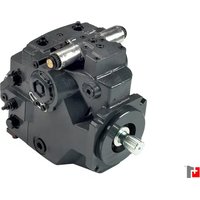
- Digital Displacement
- DDP096 pump and DPC12 controller
- Contents
- General information
- Technical specifications
- DDP characteristics
- Control operation
- Model code
- Mechanical installation
- Electrical installation
- Commissioning and troubleshooting
- Overview
- About the DDP
- Theory of operation
- Multi-outlet pump
- Features and benefits
- Most energy-efficient system
- Fastest response time
- Digitally controlled
- Compact and quiet
- Expanded modularity
- General safety warnings
- Fluid under high pressure
- OEM responsibility
- Warning
- Pressure relief
- Failure and fault states
- Intended use
- Improper use
- Personnel qualifications
- DDP096 pump specifications
- DDP general specifications
- DPC12 controller specifications
- Fuses
- Pressure sensors for DPC12
- General ratings
- Environmental standards and criteria
- LED messages
- DPC12 housing
- Performance
- Overall pump efficiency
- Idle losses
- Pump shrinkage
- Discharged flow
- Input torque
- Electronic control losses
- Noise characteristics
- Control modes, limits, and features
- Control modes and sources
- Limits
- Other features
- Control diagrams
- Example use cases
- Controller interaction
- PLUS+1\*CAN/USB gateway
- Configuration and tuning
- Commissioning mode
- Fire
- Pump
- Raw
- Displacement
- Diagnostics and errors
- DDP model code
- Model code breakdown
- DDP part options
- Pump transport and handling
- Caution
- Storage
- Installation requirements
- Pump arrangement
- Pump shaft coupling
- Understanding and minimizing system noise
- Air removal
- Removing air by gravity
- Removing air with an auxiliary pump
- Removing air through the DDP outlet port
- Removing air by submersion
- Flushing
- Filtration
- Controller mounting
- Top view dimensions
- Single-outlet pump dimensions
- Multi-outlet pump dimensions
- Multi-outlet pump rear view dimensions
- Controller dimensions
- Wiring overview
- Machine wiring guidelines
- Machine welding guidelines
- CAN bus installation
- System diagnostic connector
- Grounding
- Connectors
- DEUTSCH mating connector part information
- Controller connectors
- Basic commissioning procedure
- Commissioning and troubleshooting with PLUS+1 Service Tool
- Initial procedure
- Commissioning DDP valves and hydraulic installation
- Further system commissioning and validation
- Symptoms and diagnosis
- Serviceability
- Products we offer:
- Go to www.danfoss.com for further product information.
- Hydro-Gear
- Daikin-Sauer-Danfoss
- Danfoss
Brand : DANFOSS
Model : DDP096
Category : Pump