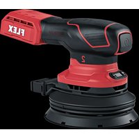
ORE 2-125 18-EC - Sander Flex - Free user manual and instructions
Find the device manual for free ORE 2-125 18-EC Flex in PDF.


| Product type | Cordless multi-function sander |
| Brand | Flex |
| Model | ORE 2-125 18-EC |
| Rated voltage | 18 Vdc |
| No-load speed | 6000 – 10000 min⁻¹ |
| Weight (without battery) | 1.0 kg |
| Compatible battery capacities | 2.5 Ah or 5.0 Ah |
| Operating temperature | -10 to 40 °C |
| Storage temperature | < 50 °C |
| Pad type | Velcro (hook-and-loop) |
| Speed levels | 4 (6000, 7500, 8000, 10000 min⁻¹) |
| Sound pressure level | 78 dB(A) |
| Sound power level | 86 dB(A) |
| Vibration value | 3 m/s² |
| Dust extraction connection | Yes (short/long adapter, dust bag) |
| Intended use | Dry sanding of wood, plastic, paint, filler |
| Protection class | II (double insulation) |
| Compliance standards | EN 62841, directives 2014/30/EU, 2006/42/EC, 2011/65/EU |
| Maintenance | Clean the ventilation slots regularly with dry compressed air |
| Spare parts | Available at www.flex-tools.com |
| Included accessories | Dust bag, short and long dust extraction adapter |
| Speed memory | Yes (last level saved) |
| Restart after power cut | No, requires pressing the switch |
Frequently Asked Questions - ORE 2-125 18-EC Flex
User questions about ORE 2-125 18-EC Flex
0 question about this device. Answer the ones you know or ask your own.
Ask a new question about this device
Download the instructions for your Sander in PDF format for free! Find your manual ORE 2-125 18-EC - Flex and take your electronic device back in hand. On this page are published all the documents necessary for the use of your device. ORE 2-125 18-EC by Flex.
USER MANUAL ORE 2-125 18-EC Flex
natural_image
Line drawings of three Flex industrial robotic arms with mounting base (no text or symbols)de Originalbetriebsanleitung....6
en Original operating instructions....11
fr Notice d'instructions d'origine ....16
it Istruzioni per l'uso originali....21
es Instrucciones de funcionamiento originales....26
pt Instruções de serviço originais 31
nl Originele gebruiksaanwijzing....36
da Originale driftsvejledning 41
no Originale driftsanvisningen....46
SV Originalbruksanvisning 51
fi Alkuperäinen käyttöohjekirja....56
el Auθεντικές οδηγίες χειρισμού....61
tr Orijinal işletme kılavuzu....66
pl Instrukcja oryginalna....71
hu Eredeti üzemeltetési útmutató ....76
cs Originální návod k obsluze 81
sk Originálny návod na obsluhu 86
hr Originalna uputa za rad....91
sl Izvirno navodilo za obratovanje 96
ro Instructiuni de functionare originale....101
bg Оригинално упътване за експлоатация 106
ru Оригинальная инструкция по эксплуатации .... 111
et Originaalkasutusjuhend 117
It Originali naudojimo instrukcija 122
Iv Lietošanas pamācības oriģināls.... 127
ar
......132
ترجمة لإرشادات التشفيل الأصلية
A
B
natural_image
Technical line drawing of a mechanical device with an arrow indicating direction (no text or symbols present)C
natural_image
Technical diagram of a mechanical assembly showing a gear-like component with internal components and alignment lines (no text or symbols)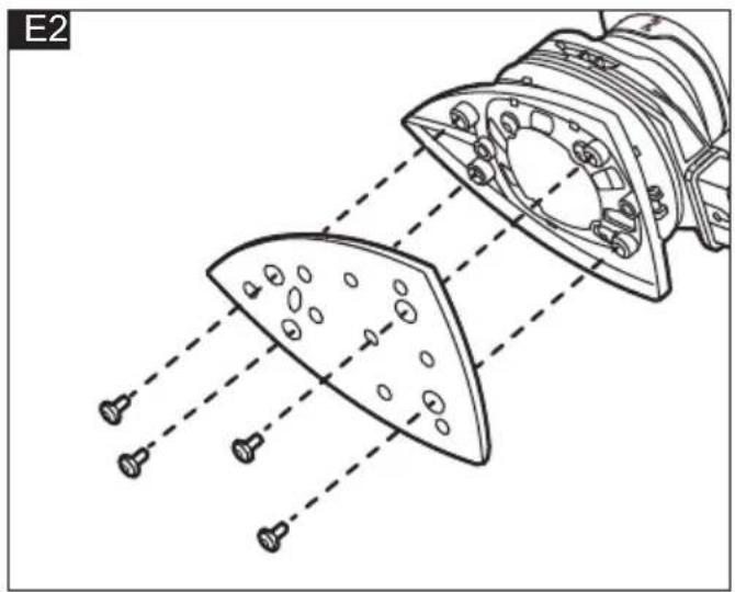
natural_image
Technical line drawing of a mechanical component with internal parts and alignment lines (no text or symbols)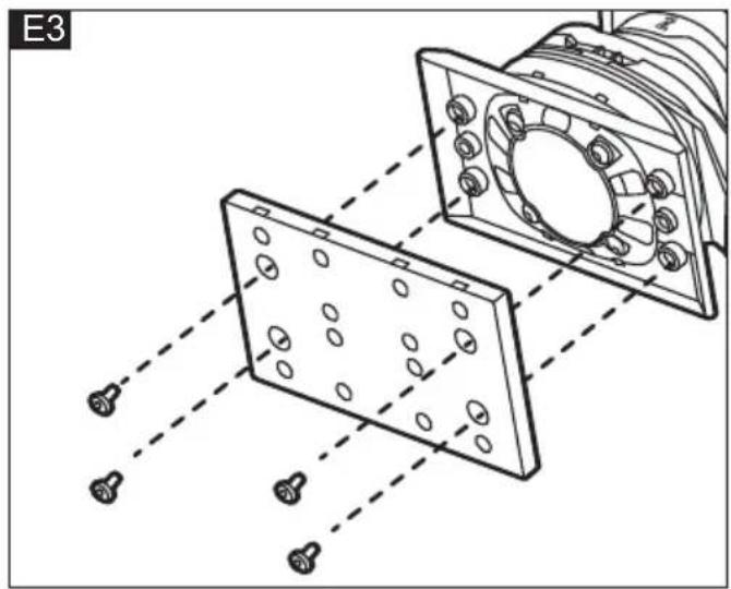
natural_image
Technical diagram showing two mechanical components with alignment lines and bolt holes, no text or symbols present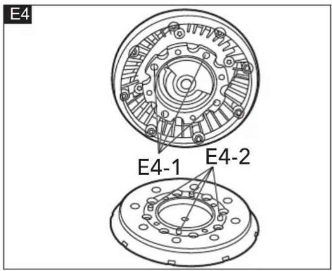
natural_image
Technical line drawing of a mechanical component with two views, one showing a cutaway view and the other showing a close-up with arrows indicating direction (no text or symbols)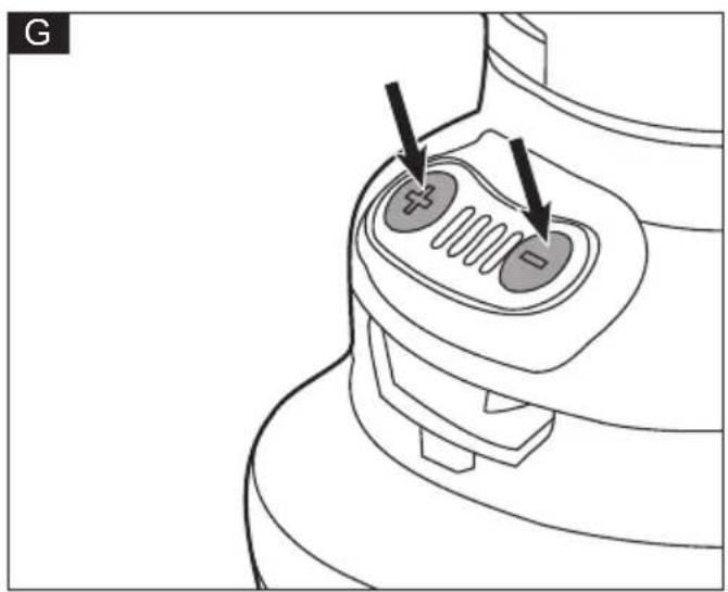
natural_image
Line drawing of a device's internal components with two arrows pointing to specific areas (no text or symbols)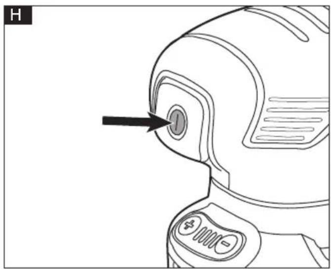
natural_image
Line drawing of a robot's interior panel with a black arrow pointing to the button (no text or symbols)Symbols on the power tool

Symbols used in this manual

WARNING!
Denotes impending danger. Non-observance of this warning may result in death or extremely severe injuries.

CAUTION!
Denotes a possibly dangerous situation. Non-observance of this warning may result in slight injury or damage to property.

NOTE
Denotes application tips and important information.
Symbols on the power tool

Read the instructions

Wear goggles!

Wear ear protection!

Wear mask!

Class II tool

Disposal information for the old machine
For your safety

WARNING!
Before using the power tool, please read the follow:
- these operating instructions,
- the "General safety instructions" on the handling of power tools in the enclosed booklet (leaflet-no.: 315.915),
– the currently valid site rules and the regulations for the prevention of accidents.
This power tool is state of the art and has been constructed in accordance with the acknowledged safety regulations.
Nevertheless, when in use, the power tool may
be a danger to life and limb of the user or a third party, or the power tool or other property may be damaged.
The cordless orbital sander may be used only –asintended,
– in perfect working order.
Faults which impair safety must be repaired immediately.
Intended use
The cordless orbital sander is intended
– for commercial use in industry and trade,
– for sanding wood, plastic, paint, filler and similar materials using the dry sanding process,
- for use with Velcro sanding sheet and accessories which are indicated in these instructions or which are recommended by the manufacturer.
Safety instructions for orbital sander

WARNING!
Read all safety warnings, instructions, illustrations and specifications provided with this power tool. Failure to follow all instructions listed below may result in electric shock, fire and/or serious injury. Save all warnings and instructions for future reference.
■ Attention Risk of fire! Avoid overheating the material to be ground and the grinder. Always empty the dust container before taking breaks from work. Grinding dust in the dust sack, microfilter, paper sack (or in the filter sack or filter of the dust extractor) may self-ignite under unfavourable conditions, e.g. caused by flying sparks when grinding metals. It is particularly hazardous if the grinding dust is mixed with paint or polyurethane residue or other chemical substances and if the material is ground for a long time until hot.
■ Dust released from materials, such as lead paints, some types of wood, minerals and metal, may be hazardous to the operator or people in the vicinity. Inhaling or touching these dusts may result in respiratory diseases and/or allergic reactions.
– Ensure the work place is well ventilated!
– If possible, use external dust extraction.
- It is recommended to wear a respirator mask belonging to filter class P2.
■ Use the power tool for dry sanding only. If
water penetrates the power tool, there is an increased risk of electric shock.
- Secure the workpiece. A workpiece is held more securely in a clamping device or vice than by hand.
- Keep the workplace clean. Material mixtures are especially dangerous. Light metal dust may burn or explode.
■ Do not work on materials which release hazardous substances (e.g. asbestos).
■ Never grind light metals which have a magnesium content greater than 80%. Risk of fire!
■ Before using the machine, check that the grinding tools have been installed and secured correctly. Switch on the power tool at no load for 30 seconds!
■ When metal is being ground, flying sparks occur. Ensure that nobody can be endangered by flying sparks.
■ Interrupt the test run immediately if violent vibrations occur or other damage is established. Check the machine to determine the cause.
■ Before putting down the sander, switch it off and wait until it comes to a standstill.
■ Do not clamp the sander in a vice.
Noise and vibration
The noise and vibration values have been determined in accordance with EN 62841.
The A evaluated noise level of the power tool is typically:
| Sound pressure level L_pA | Sound power level L_WA | |
| ORE 2-125 18-EC | 78 dB(A) 86 dB(A) | |
| OSE 2-80 18-EC | 74 dB(A) 82 dB(A) | |
| ODE 2-100 18-EC | 73 dB(A) 81 dB(A) | |
| Uncertainty K=3dB | ||
Total vibration value:
| Emission value a_h | |
| ORE 2-125 18-EC 3 | 2 m/s ^2 |
| OSE 2-80 18-EC <2 | 5 m/s ^2 |
| ODE 2-100 18-EC <2.5 m/s ^2 | |
| Uncertainty K = 1.5 m/s ^2 |
CAUTION!
The indicated measurements refer to new power tools. Daily use causes the noise and vibration values to change.
NOTE
The declared vibration total value(s) and the declared noise emission level given in this information sheet has been measured in accordance with a measurement method standardized in EN 62841 and may be used to compare one tool with another. It may be used for a preliminary assessment of exposure. The specified vibration emission level represents the main applications of the tool.
However, if the tool is used for different applications, with different cutting accessories or poorly maintained, the vibration emission level may differ.
This may significantly increase the exposure level over the total working period.
To make an accurate estimation of the vibration exposure level, it is also necessary to take into account the times when the tool is switched off or running but not actually in use.
This may significantly decrease the exposure level over the total working period.
Identify additional safety measures to protect the operator from the effects of vibration such as: maintain the tool and the cutting accessories, keep the hands warm, organization of work patterns.
WARNING:
The vibration and noise emissions during actual use of the power tool can differ from the declared value in which the tool is used; In order to protect the operator, user should wear gloves and ear protectors in the actual conditions of use.
CAUTION!
Wear ear defenders at a sound pressure above 85 dB(A).
Technical data
| Tool | ORE2-12518-EC | OSE2-8018-EC | ODE2-10018-EC | |
| Type | Orbital sander | |||
| Rated voltage | Vdc 18 | |||
| No-load speed | min ^-1 | 6000-10000 | ||
| Weight according to"EPTA Procedure 01/2003"(without battery) | kg 1.0 | 6 1.04 | 1.04 | |
| Battery 18V | AP 18.0/2.5AP 18.0/5.0 | |||
| Weight of battery | kg | AP 18.0/2.5AP 18.0/5.0 | 0.40.7 | |
| Working temperature | -10 - 40°C | |||
| Storage temperature | < 50°C | |||
| Charging temperature | 4-40°C | |||
| Charger CA 1 | 0.8/18.0, CA 18.0-LD | |||
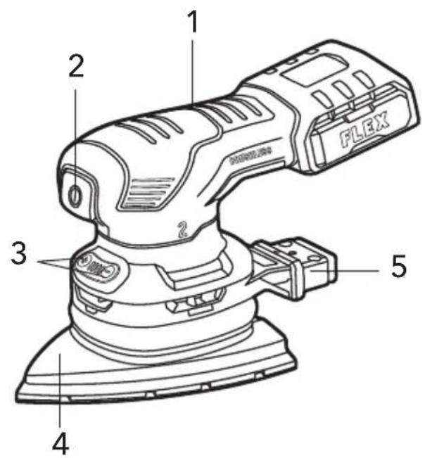
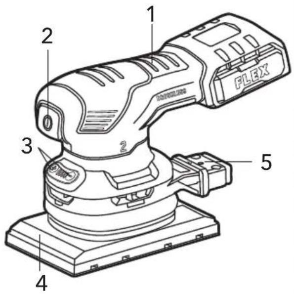
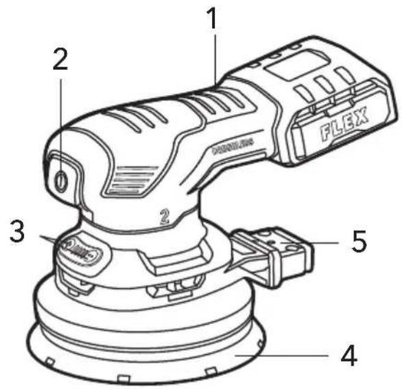
Overview (see figure A)
The numbering of the product features refers to the illustration of the machine on the graphics page.
- Insulated grip surfaces
- ON/OFF switch
- Speed setting buttons
- Sanding plate
- Dust extraction outlet
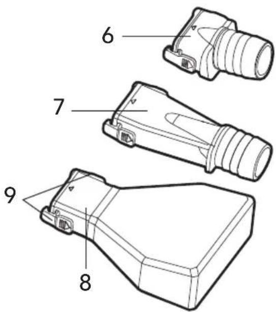
- Short dust extraction adapter
- Long dust extraction adapter
8. Dust extraction bag
9. Buckles
Operating instructions

WARNING!
Remove the battery before carrying out any work on the power tool.

NOTE
When the power tool is switched off, the tool continues running briefly.
For further information on the manufacturer's products go to www.flex-tools.com
Before switching on the power tool
Unpack the cordless orbital sander and check that here are no missing or damaged parts.

NOTE
The battery is not fully charged on delivery. Prior to initial operation, charge the battery fully. Refer to the charger operating manual.
Inserting/replacing the battery
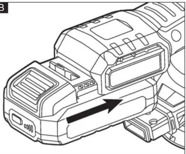
■ Press the charged battery into the power tool until it clicks into place (see figure B).
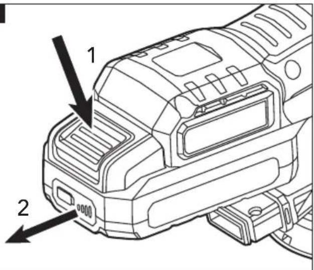
■ To remove, press the release button(1.) and pull out the battery (2.) (see figure C).

CAUTION!
When the device is not in use, protect the battery contacts. Loose metal parts may short circuit the contacts; explosion and fire hazard!
Attaching/changing the sanding sheet
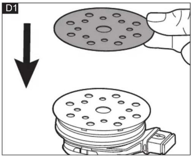
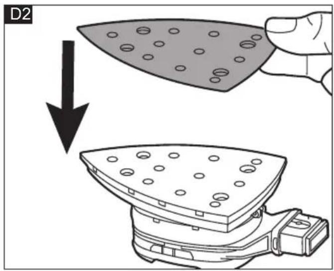
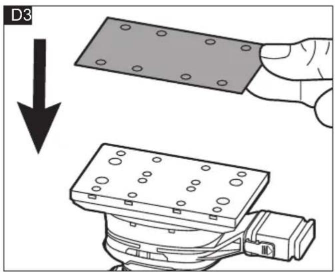
The sanding plate (4) has Velcro fasteners and is therefore designed exclusively for use with Velcro sanding sheet (see figure D1&D2&D3).
■ Remove the battery.
■ Remove used sanding sheet.
■ Remove any coarse debris from the sanding plate (4).
■ Attach new sanding sheet. Align the holes in the sanding sheet with the holes in the sanding plate (4).
■ Attach the sanding sheet by gently pressing it against the Velcro fasteners on the sanding plate (4).
Changing the sanding plate
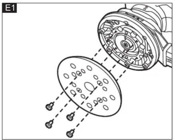
If the sanding plate (4) has worn out, it can be replaced (see figure E1&E2&E3).
■ Remove the battery.
■ Undo the four screws.
■ Remove the sanding plate (4) by pulling it downwards.
■ Attach a new sanding plate.
■ Tighten the four screws back.
NOTE: when changing the orbital sander, align the four pins (E4-2) on the sanding plate with the locating holes (E4-1) in the tool (see figure E4).
NOTE: When removing and installing the screws, the sanding plate needs to be held down so that it does not rotate when the screws are screwed in.
Attaching /removing extraction dust bag and dust extraction adapter

WARNING!
When using the sander, you must use a dust extraction bag or an external dust extraction.

WARNING!
Avoid dust accumulation at the workplace.
Dust can easily ignite.
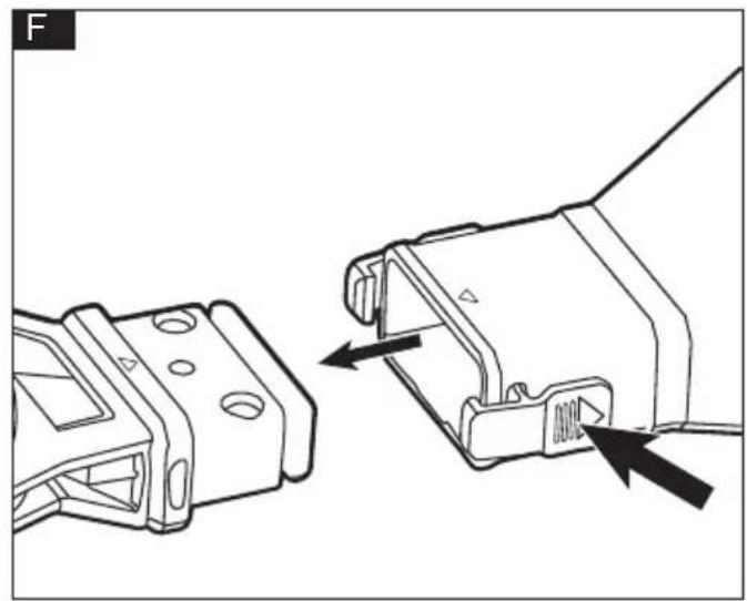
■ Align the triangle on the dust extraction bag (8) or dust extraction adapter (6&7) with the triangle on the dust extraction outlet.
■ Press the buckles on both sides of the dust extraction bag (8) or dust extraction adapter (6&7) and push the dust extraction bag (8) or dust extraction adapter (6&7) onto the dust extraction outlet (5) all the way until the buckles (9) on the dust extraction bag (8) or dust extraction adapter (6&7) snap into the groove of the dust extraction outlet (5) (see figure F).
■ To remove the dust extraction bag (8) or dust extraction adapter (6&7), press the buckles (9) on both sides of the dust extraction bag (8) or dust extraction adapter (6&7) and remove it.
■ A dust extraction hose can be connected to the short or long dust extraction adapter.
NOTE: Because the size of the battery will interfere with the dust extraction adapter, when using a short dust extraction adapter (6), only use 2.5Ah battery and using a long dust extraction adapter (7), use 2.5Ah or 5.0 Ah battery. All of the three orbital sanders are not suitable for the 8.0Ah battery.
Setting the speed (see figure G)
There are four speed levels that can be changed using the speed setting buttons (3).
Press the "+" button to increase the speed. Press "-" button to decrease the speed. The LED lights above the numbers indicate the current speed level.
The speed level can be set when the tool is already in operation.
After you turn the tool off, the memory function will remember and revert to the last active speed level the next time the tool is turned on.
The approximate OPM (oscillations per minute) are:
| Speed level /min(OPM) | |
| 1 6000 | |
| 2 7500 | |
| 3 8000 | |
| 4 10000 | |
Switching on and off
Switch power tool on or off by pressing on/off switch (2) (see figure H).

CAUTION!
Following a power failure, the switched-on power tool will not start running again.
Operating instructions

WARNING!
When the power tool is switched off, the grinding tool continues running briefly.
■ Switch on the sander and place the whole sanding sheet on the surface to be processed.
■ Applying moderate pressure, move the sander evenly over the workpiece.
■ The sanding result is determined primarily by the selection of the correct sanding sheet, the selected number of oscillations and the contact pressure.
■ Replace sanding sheets in good time.
■ An excessive increase in the contact pressure will not increase the grinding performance, but will increase the wear on the electric power tool and the sanding tool.
Maintenance and care

WARNING!
Remove the batteries before carrying out any work on the power tool.
Cleaning
■ Clean the power tool and grille in front of the vent slots regularly. Frequency of cleaning is dependent on the material and duration of use.
■ Regularly blow out the housing interior and motor with dry compressed air.
Spare parts and accessories
For other accessories, see the manufacturer's catalogues.
Exploded drawings and spare-part lists can be found on our homepage:
www.flex-tools.com
Disposal information

WARNING!
Render redundant power tools unusable:
- battery operated power tool by removing the battery.

EU countries only
Do not throw electric power tools into the household waste!
In accordance with the European Directive 2012/19/EU on Waste Electrical and Electronic Equipment and transposition into national law used electric power tools must be collected separately and recycled in an environmentally friendly manner.

Raw material recovery instead of waste disposal.
Device, accessories and packaging should be recycled in an environmentally friendly manner. Plastic parts are identified for recycling according to material type.

WARNING!
Do not throw batteries into the household waste, fire or water. Do not open used batteries.
EU countries only: In accordance with Directive 2006/66/EC defective or used batteries must be recycled.

NOTE
Please ask your dealer about disposal options!
C €-Declaration of conformity
We declare on our sole responsibility that the product described in "Technical specifications" conforms to the following standards or normative documents: EN 62841 in accordance with the regulations of the directives 2014/30/EU, 2006/42/EC, 2011/65/EU.
Responsible for technical documents: FLEX-Elektrowerkzeuge GmbH, R & D Bahnhofstrasse 15, D-71711 Steinheim/Murr
Peter Lameli Klaus Peter Weinper Technical Director Head of Quality Department (QD)
Exemption from liability
The manufacturer and his representative are not liable for any damage and lost profit due to interruption in business caused by the product or by an unusable product. The manufacturer and his representative are not liable for any damage which was caused by improper use of the product or by use of the product with products from other manufacturers.

Declaration of Conformity
We as the manufacturer: FLEX
declare under our sole responsibility, that the product(s) described under „Technical specifications“ fulfills all the relevant
provisions of The Supply of Machinery
(Safety) Regulations S.I. 2008/1597 and also fulfills all the relevant provisions of the following UK Regulations:
Electromagnetic Compatibility Regulations
S.I. 2016/1091, The Restriction of the Use of Certain Hazardous Substances in Electrical and Electronic Equipment Regulations
S.I. 2012/3032 and are manufactured in accordance with the following designated Standards:
BS EN62841-1:2015
BS EN62841-2-4:2014
BS EN IEC 55014-1:2021
BS EN IEC55014-2:2021
Place of declaration: Steinheim, Germany.
Responsible person: Peter Lameli, Technical
Contact details for Great Britain: FLEX Power
Tools Limited, Unit 8 Anglo Office Park, Lincoln Road, HP 12, 3RH Buckinghamshire, United Kingdom.
Technical Director Head of Quality
Department (QD)
1.09.2023
2006/42/WE, 2011/65/UE.
natural_image
Vertical sequence of black circular icons representing various workplace and safety symbols (person, helmet, headset, head, frame, trash bin) — no text or labels present.




- Symbols on the power tool
- Symbols used in this manual
- WARNING!
- CAUTION!
- NOTE
- For your safety
- Intended use
- Safety instructions for orbital sander
- Noise and vibration
- WARNING:
- Overview (see figure A)
- Dust extraction bag
- Buckles
- Operating instructions
- Before switching on the power tool
- Inserting/replacing the battery
- Attaching/changing the sanding sheet
- Changing the sanding plate
- Attaching /removing extraction dust bag and dust extraction adapter
- Avoid dust accumulation at the workplace.
- Setting the speed (see figure G)
- Switching on and off
- Maintenance and care
- Cleaning
- Spare parts and accessories
- Disposal information
- Raw material recovery instead of waste disposal.
- C €-Declaration of conformity
- Exemption from liability
- Declaration of Conformity
Brand : Flex
Model : ORE 2-125 18-EC
Category : Sander