
FR 30 SM 45 TOUCH - Industrial cleaning machine Ghibli & Wirbel - Free user manual and instructions
Find the device manual for free FR 30 SM 45 TOUCH Ghibli & Wirbel in PDF.

| Product type | Walk-behind floor scrubber |
| Brand | Ghibli & Wirbel |
| Model | FR 30 SM 45 TOUCH |
| Power supply | Gel or lead-acid battery (24 V) |
| Installed power | 600 W |
| Cleaning width | 430 mm |
| Suction width | 650 mm |
| Theoretical performance | 1720 m²/h |
| Solution tank capacity | 30 L |
| Recovery tank capacity | 33 L |
| Dimensions (L x W x H) without squeegee | 1210 x 560 x 1020 mm |
| Empty weight | 66 kg |
| Weight with 50 Ah batteries | 104 kg |
| Weight with 76 Ah batteries | 121 kg |
| Brush motor | 200 W, 120 rpm |
| Suction motor | 400 W, vacuum 1189 mmH2O, airflow 28 L/s |
| Brush specific pressure | 17.4 g/cm² |
| Max noise level | 64 dB(A) |
| Vibration (ISO 5349) | < 2.5 m/s² |
| Work cycles | Washing, scrubbing, drying, combinations |
| Control panel | Touchscreen, switches |
| Routine maintenance | Tank draining and cleaning, filter cleaning, squeegee check |
| Included accessories | PPL brush ø0.7, squeegee, filling hose, manuals |
Frequently Asked Questions - FR 30 SM 45 TOUCH Ghibli & Wirbel
User questions about FR 30 SM 45 TOUCH Ghibli & Wirbel
0 question about this device. Answer the ones you know or ask your own.
Ask a new question about this device
Download the instructions for your Industrial cleaning machine in PDF format for free! Find your manual FR 30 SM 45 TOUCH - Ghibli & Wirbel and take your electronic device back in hand. On this page are published all the documents necessary for the use of your device. FR 30 SM 45 TOUCH by Ghibli & Wirbel.
USER MANUAL FR 30 SM 45 TOUCH Ghibli & Wirbel
natural_image
Line drawing of a cleaning or cleaning service robot with wheels and a circular base (no text or symbols)FR30
SM45 Touch
RAPID30
SM 45 TOUCH

CE
49.0265.00
ed. 06/2022
EN Use and Maintenance
natural_image
Technical line drawing of an internal vehicle engine compartment with hoses and control panels (no text or symbols)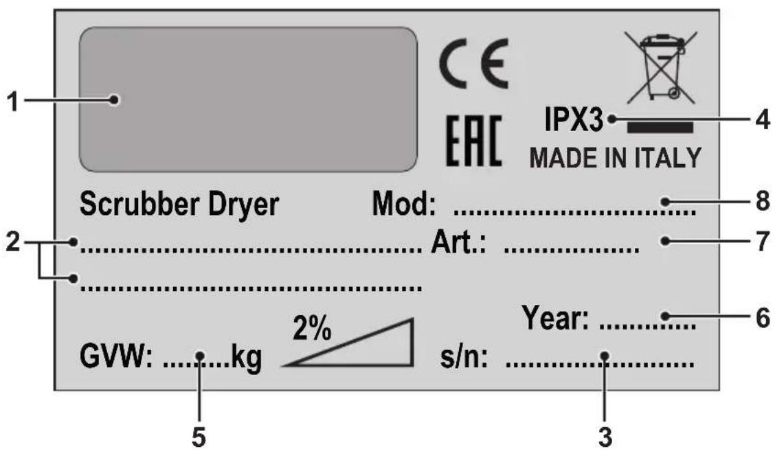
| 1 2 3 4 | ||||
| IT | Produttore Caratteristiche elettriche N° Matricola Grado di protezione | |||
| EN | Manufacturer Electrical characteristics Serial N° Degree of protection | |||
| FR | Producteur Caractéristiques électriques N° Matricule Degré de protection | |||
| DE | Hersteller Elektrische Eigenschaften Seriennummer Schutzgrad | |||
| ES | Fabricante Características eléctricas N° Matrícula Grado de protección | |||
| PT | Produtor Características eléctricas Número de série | Grau de protecção | ||
| NL | Producent | Elektrische eigenschappen | Serienummer | Beschermingsgraad |
| CS | Výrobce | Elektrické údaje Výrobní č. | Úroveň ochrany | |
| RU | Изготовитель | Электрические характеристики | Заводской No | Степень защиты |
| AR | الصنع | الموصفات الكهربائية | الرقم التسلسلي | درجة الحمالية |
| 5 6 7 8 | ||||
| IT | Peso in ordine di marcia | Anno di costruzione | Codice articolo | Modello |
| EN | Weight in running order | Year of manufacture | Item code | Model |
| FR | Poids en ordre de marche | Année de construction | Référence de l'article | Modèle |
| DE | Gewicht bei Betrieb | Baujahr | Artikelnummer | Modell |
| ES | Peso en orden de marcha | Año de fabricación Código del artículo Modelo | ||
| PT | Peso em ordem de marcha | Ano de construcción | Código do artigo | Modelo |
| NL | Gewicht in rijklare toestand | Bouwjaar | Artikelcode | Model |
| CS | Hmotnost v provozním stavu | Rok výroby | Kód položky | Model |
| RU | Эксплуатационный вес Год выпуска Код изделия | Модель | ||
| AR | الوزن في وضعية التشغيل | سنة الصنع | رمز المنتج | الطراز |
EN English ...... ENGLISH -1
(Translation of original instructions)
FR Français ...... FRANÇAIS -1
Thank you for choosing one of our cleaning products.
The floor scrubber dryer that you have purchased has been designed to satisfy the user in terms of ease of use and reliability over time.
We are aware that in order for a good product to stay that way, over time, it requires continuous updates aimed at meeting the expectations of those who use it on a daily basis. For this reason, we hope that you will not only be a satisfied customer but also a partner who does not hesitate to give us your opinions and ideas originating from your personal day-to-day experience.
Contents
Technical data......EN-3
1.1 Introduction......EN-5
2.1 Getting to know the machine......EN-5
3.1 Unpacking......EN-5
3.1.a Standard machine equipment ......EN-5
4.1 Assembling the components......EN-5
4.1.a Wiper assembly......EN-5
4.1.b Brush assembly......EN-5
4.1.c Installing and connecting the batteries......EN-6
5.1 Charging the battery......EN-6
5.1.a Charging the battery using the on board battery charger (if present) EN-6
5.1.b Charging the battery using an external battery charge ......EN-7
6.1 Control panel......EN-7
6.2 Working cycle example ......EN-8
7.1 Filling the tank ......EN-8
8.1 Operation......EN-8
8.1.a Checks before use......EN-8
8.1.b Preparing the machine and choosing the cycle....EN-8
8.1.c Using the machine ......EN-9
8.1.d End of use and switching off....EN-9
8.1.e Maximum recovery tank water level alarm......EN-9
9.1 Draining the recovery water......EN-10
10.1 Maintenance and cleaning......EN-10
10.1.a Emptying and cleaning the clean water tank ....EN-10
10.1.b Cleaning the recovery water tank ...... EN-10
10.1.c Cleaning the squeegee......EN-11
10.1.d Cleaning the clean water filter...... EN-11
10.1.e Replacing the brush....EN-11
10.1.f Replacing the squeegee rubber blades ...... EN-11
10.1.g Cleaning the recovery water tank......EN-12
10.1.h Replacing the fuses ...... EN-12
10.1.i Wiper adjustment....EN-12
10.1.I Battery charger and digital instrument configuration......EN-13
Troubleshooting....EN-14
11.1 Warranty ......EN-15
Wiring diagram ......EN-16
Touch basic......EN-16
Technical data
| Type of use Operator on ground | |
| Characteristics | |
| Power supply Battery | |
| Power supply voltage See technical data plate | |
| Installed load 600 W | |
| Forward movement Manual | |
| Washing width * 430 mm | |
| Drying width 650 mm | |
| Theoretical hourly working capacity 1720 m | ^2/h |
| Brushes / Pad | |
| Diameter / Number 430mm/17"x1 | |
| Motor power / number 200 Wx1 | |
| Motor speed 120 giri/min. | |
| Specific pressure 17,4 gr/cm | ^2 |
| Head weight 18 kg | |
| Aspiration | |
| Motor power 400 W | |
| Negative pressure 1189 mmH | _2O |
| Air flow rate 28 l / sec | |
| Noise level | Max. 64 dB (A) |
| Traction | |
| Engine power | --- |
| Tank | |
| Recirculation | No |
| Solution capacity | 30 l |
| Recovery capacity 33 l | |
| Dimensions (lxwxh) without wiper | 1210 x 560 x 1020 mm |
| Vibrations ISO 5349 m/sec ^2 | < 2,5 |
| Weight | |
| Empty weight 66 Kg | |
| Weight with batteries 50 Ah / 76 Ah | 104 Kg / 121 Kg |
| Weight in running order GVW 50 Ah / 76 Ah | 134 Kg / 151 Kg |
* The washing width is intended with the machine operating and the brush pressed down.
| Accessories | |
| 0.7 ø PPL brush 40.0002.00 POLY 0,7 | |
| Front rubber wiper element 39.0129.00 | |
| Rear rubber wiper element 39.0130.00 | |
| Optional accessories | |
| 0.9 ø PPL strong brush 40.0102.00 POLY 0,9 | |
| 1.2 ø grit 80 tynex brush 40.0202.00 | |
| Drive mechanism 40.1007.00 | |
| Front anti-oil rubber wiper element 39.0131.00 | |
| Gomma tergitore posteriore antiolio 39.0132.00 | |
1.1 INTRODUCTION

DANGER:
Before using the machine, carefully read the attached "SAFETY WARNINGS FOR THE FLOOR SCRUBBER DRYER" manual.
2.1 GETTING TO KNOW THE MACHINE (Fig. 1)
1) Guide handle.
2) Control console.
3) Squeegee activation lever.
4) Water supply tap.
5) Solution tank.
6) Tank cover.
7) Clean water filling opening.
8) Wheels.
9) Brush head.
10) Brush.
11) Squeegee.
12) Recovery water drain hose.
13) Squeegee water aspiration hose.
14) Recovery water tank.
15) Clean water drain/level tube.
16) Water filter.
17) Clean water filter.
20) Touch sensor for starting traction and brush rotation.
3.1 UNPACKING (Figg. 1-2)
Once the packaging has been removed as shown in the instructions on the packaging itself, check that the machine and all the components supplied are intact.
If any evident damage is found, contact the area agent and the carrier within 3 days of receipt.
- Remove the bag (21) containing the accessories.
- Cut the strap (22).
- Remove the wooden blocks (23 and 24).
-
Lift the brush flange (9) by pressing down on the pedal (19) (see relative paragraph).
-
Lift the wiper support (25) by lifting the handle (3 Fig. 1) (see relative paragraph).
- Position a chute and unload the machine from the bench.
3.1.a - Standard machine equipment (Fig. 3)
The accessories supplied are as follows:
10) Brush.
11) Wiper.
26) Water filling hose.
27) Machine use and maintenance manual.
28) Battery charger instruction manual (if present).
29) Battery charger power cable (if present).
30) Filter for clean water tank opening.
4.1 ASSEMBLING THE COMPONENTS
4.1.a - Wiper assembly (Fig. 4)
- Loosen the two handwheels (32) located on the wiper (11).
- Assemble the wiper (11) on the support (25), tightening the two handwheels (32).
- Connect the tube (13) to the wiper connector (33).

N.B.:
Perform the previous operations with the wiper support lowered.
4.1.b - Brush assembly (Fig. 5)

HAZARD:
Operation to be performed by two people!
- Slightly lift the head (9) and remove the polystyrene protection (34).
- Assemble the brush as described in the paragraph "replacing the brush".
4.1.c - Installing and connecting the batteries (Fig. 6)

WARNING:
CHECK THAT THE RECOVERY TANK AND THE CLEAN WATER TANK ARE EMPTY.
- Disconnect the plug (35).
- Press the button (36) and lift the tank (14) until completely overturned.
- Position the batteries (37) as shown in the figure and connect them as shown on the chart in Fig. 6 using the cables supplied.
- Tighten the terminals (38) using an insulated wrench.
- Lower the tank (14) until a coupling "click" is heard.
- Connect the plug (35) to the relevant socket (39).

N.B.:
The battery must be connected by specialised personnel.
5.1 CHARGING THE BATTERY

DANGER:
Charge the batteries in rooms which are well-ventilated and comply with applicable regulations in the country of use.
For safety-related information, follow what is described in chapter 1 of this manual.

WARNING:
For information and warnings about the battery and on board battery charger (if present) follow what is described in the battery charger manual enclosed with this document.

WARNING:
When the machine leaves the factory, it is calibrated to operate with gel batteries.
If other types of batteries are installed, see the paragraph "Parameter setting". The use of gel batteries with calibration for acid or other batteries is prohibited.

NOTE:
10 hours are needed for complete battery charging. Avoid partial recharges.
5.1.a - Charging the battery using the on board battery charger (if present) (Fig. 7)
- Move the machine close to a mains electricity socket.

WARNING:
It is important to first connect the cable (41) to the socket (42) and then connect the cable (41) to the power socket.
- Take the cable (41) from its seat and connect it to the socket (42) on the machine, then connect the other end to the mains power socket.
- Check that the green LED (43) flashes 2 times and then goes from the color "Green" to continuously lit "Red".

WARNING:
Make sure that the mains electrical voltage is compatible with the battery charger's operating voltage (230 Vac for the European market; 115 Vac for the American market; 50/60 Hz).
- Leave the batteries to charge until the "Green" LED (43) lights up, then remove the power cable (41) and put it away.
5.1.b - Charging the battery using an external battery charger (Fig. 8)

WARNING:
It is important to first connect the plug (35) to the socket (44) of the battery charger and then connect the battery charger to the mains socket, otherwise the batteries will not charge.
- Move the machine close to the battery charging station.
- Remove the battery plug (35) from the system socket (39).
- Connect the battery plug (35) to the external battery charger socket (44).
- Once battery charging is complete, reconnect the battery plug (35) to the system socket (39).
6.1 CONTROL PANEL (Fig. 9)
20) Sensor for starting brush/es rotation
Acting on the sensor (20), with the switch
(45) “” and the switch (52) “” inserted, it starts the rotation of the brush and the water supply.
45) Main switch " ⏻"
Pressing the switch to "I", it inserts voltage to the circuits, enabling commands and their switches.
To remove power to the circuits, repress the switch.
46) Aspirator start switch "

The operation of the switch is enabled from the switch (45) “” in position “1”.
Press the switch (46) “”, starts the operation of the vacuum cleaner.
To turn off the fan, press the switch (46), the turbine will continue to function for a few seconds in order to aspirate the liq-
uid present on the floor, after which it will turn off automatically
47) Switch for enabling the brush / sole-noid
Press the switch (47), it enables the rotation of the brush and the opening of the solenoid valve; the operation of the same is controlled by the sensor (20). To stop the supply of water, close the tap (4).
4) Water quantity adjustment tap
- Turn the tap (4) counter-clockwise to increase the quantity of water or turn it clockwise to decrease it.
48) Status indicator battery discharge
Lights when the switch (45) is pressed, indicating the charge status of the battery.
- When the LED (49) is illuminated, it indicates that the battery charge status is at maximum.
- When the LED (50) is illuminated, it indicates that the battery charge status is at about half.
- When the LED (51) is illuminated (red LED), it indicates that the battery charge status is at minimum.
With low battery (red LED (51) lit), the machine turns off or does not start; it is necessary to recharge the battery.
6.2 WORKING CYCLE EXAMPLE (Fig. 9)
Setting a washing cycle with brushes and drying.
- Press the switch (47) to enable the rotation of the brush and the water supply.
- Press the switch (46) to start the vacuum cleaner.
7.1 FILLING THE TANK
(Fig. 11)

WARNING:
Only add clean mains water to the tank at a temperature no greater than 50^ C.
- Remove the hose (26) supplied, connect one end (31) to a tap and insert the other end (52) in the tank (5).
- Check that the tap (53) is open.
- Turn on the tap and fill the tank (5).
- The level of water contained in the tank is displayed on the transparent tube (15).
- Pour the detergent fluid in the tank.

NOTE:
Use non-foamy detergents only. For the quantities, follow the instructions provided by the detergent manufacturer according to the type of dirt.

DANGER:
If the detergent comes in contact with the eyes and/or skin or if swallowed, refer to the use and safety information booklet provided by the manufacturer of the detergent.
8.1 OPERATION (Fig. 1)
8.1.a - Checks before use
- Check that the exhaust tube (12) of the recovery tank is properly coupled and properly sealed.
- Check that the connector (54) on the squeegee (11) is not blocked and that the
hose is connected correctly.
- Check that the clean water exhaust tube (15) is correctly coupled to the supports and that the tap (53) is open.
- Press the switch (45) and check the battery charge on the indicator discharge (48).
8.1.b - Preparing the machine and choosing the cycle (Fig. 9-12)
- Press the switch (45 Fig.9) in position "I".
- Release the lever (3 Fig. 12) and lower it; the floor squeegee (11 Fig. 12) is lowered.
- Press the pedal (19 Fig. 12), detach it from the clamp, and lift it, the brush (10 Fig. 12) is lowered.
Working cycle:
- The machine can perform 4 working cycles:
Drying only cycle:
- To run the drying cycle press the switch (46 Fig. 9), you start the vacuum cleaner.
Brushing only cycle:
- To make only the brushing cycle press the switch (47 Fig. 9) to enable the rotation of the brush. Press the control located on the handle to start the rotation of the brush.
Washing, brushing cycle:
- Press the button (47 Fig. 9) to enable the rotation of the brush
Press the control, positioned on the handle, to start the rotation of the brush.
Washing, brushing, drying cycle:
- Press the switch (46 Fig. 9) to start the vacuum cleaner, the button (47 Fig. 9) to enable the rotation of the brush and the water supply.
Press the control on the handle to start the rotation of the brush and the water supply.
8.1.c - Using the machine (Fig. 1)
- After starting the machine and choosing the type of cycle, start cleaning, by pushing the machine using the handle (1 Fig. 1) and acting on the sensor (20, Fig. 1).

NOTE:
Pay attention to particularly delicate floors; do not use the machine while it's stopped and the brush rotation on.
For particularly dirty spots, adjust the traction speed to "0" so the brush will rotate in the same position, without straining the traction motor.

NOTE:
The proper cleaning and drying of the floor is done by pushing the machine forwards; if you go backwards the machine will not perform drying; in this phase, always lift the wiper to avoid damaging the blades.
- If necessary, adjust the quantity of washing water using the tap (4 Fig. 1).
- Check the battery charge via the discharge indicator (48 Fig. 9).
8.1.d - End of use and switching off (Fig. 9-13)
- At the end of the cleaning, before turning off the machine, stop the water supply and the rotation of the brush, using the switch (47 Fig. 9).
- Lift up the brush by pressing the pedal (19 Fig. 13) as far as it will go, fitting it in the designated slot.
- Continue with the aspirat inserted to suck all the liquid present on the floor, then turn off the vacuum off cleaner by pressing the switch (46 Fig. 9).
- Lift the squeegee (11 Fig. 13) by lifting the lever (3 Fig. 13).

WARNING:
Always lift the wiper and the end piece after finishing the cleaning operations because this avoids the deformation of the rubber blades and of the brush hairs.
- Press the switch (45 Fig. 9) to turn off the machine.

WARNING:
If the machine will not be used for a few days, it is recommended to disconnect the plug (35 Fig. 7-8) from the relative socket.
8.1.e - Maximum recovery tank water level alarm (Fig. 14)
If during use of the machine, the vacuum cleaner is switched off, it means that the level of liquid in the recovery tank has reached the maximum level.
Go to the water drainage station and drain the recovery tank as shown in the relative paragraph.

NOTE:
For the proper operation of the level sensors it is required to properly clean the inside of the tank (14 Fig. 14).
9.1 DRAINING THE RECOVERY WATER
(Fig. 15)
At the end of the washing cycle or when the recovery water tank (14) is full, it is necessary to empty the tank by proceeding as follows:

NOTE:
To dispose of the recovery water, comply with the standards in force in the country in which the machine is used.
- Position the machine near to a drain outlet.
- Disconnect the hose (12) from the support.
- Remove the cap (56) from the hose (12) and drain all the water contained in the tank.

NOTE:
The amount of water that comes out can be modulated by pressing on the end of the tube (12).
- Put the cap (56) back on the hose (12) and reposition it on the relative support.
10.1 MAINTENANCE AND CLEANING

WARNING:
All maintenance operations must be performed with the machine off and tanks empty.
OPERATIONS TO PERFORM DAILY
10.1.a - Emptying and cleaning the clean water tank (Fig. 16)

WARNING:
At the end of the washing operations, it is compulsory to drain and clean the clean water tank (5) to prevent deposits or scaling.
After draining the recovery water tank, drain the clean water tank as follows:
- Position the machine over a drain outlet.
- Disconnect the tube (15) from the hooks, close the tap (53), lower the tube to the ground on the drain outlet, open the tap (53) and let the water drain completely.
- Wash the inside of the tank, leaving the drain hose open and adding clean water through the top opening.
- When cleaning is complete, lift the tube (15), leaving the tap (53) open; couple the tube in its recesses.
- To completely drain the water from the tank (5) disconnect the tube (57) from the quick connector (58) then turn the connector downwards, letting the water drain completely; or remove the filter cover (59).
10.1.b - Cleaning the recovery water tank (Fig. 17)

WARNING:
At the end of the washing operations, it is compulsory to clean the recovery water tank to prevent deposits or scaling and the proliferation of bacteria, odours or mould.
- Drain the recovery water as shown in the relative paragraph, positioning the machine over a drain outlet.
- Remove the cover (6).
- Leaving the hose (12) lowered and the cap off, pour water into the tank (14)
through a hose, cleaning it until clean water comes out of the drain hose.
- Clean the level probes (55) using a damp cloth, taking care not to deform them.
- Replace all the components in reverse order.
10.1.c - Cleaning the squeegee (Fig. 4)
In order to clean the squeegee correctly (11), it is necessary to remove it as follows:
- Disconnect the hose (13) from the squee-gee (11).
- Loosen the knobs (32) and remove the squeegee (11).
- Wash the squeegee and in particular the rubber blades (60) and the inside of the aspiration connector (33).

NOTE:
If, during washing, it is clear that the rubber blades (60) are damaged or worn, it is necessary to replace them or turn them over.
- Replace all the components in reverse order.
OPERATIONS TO PERFORM WHEN NECESSARY
10.1.d - Cleaning the clean water filter (Fig. 18)

NOTE:
Before cleaning the filter, make sure the clean water tank is empty.
- Unscrew and remove the cover (59).
- Remove the filter (17) and wash it in running water.
- Refit the filter (17) in its seat, then tighten the cover (59).
10.1.e - Replacing the brush (Fig. 19)
It is necessary to replace the brush when it is worn more than 2 cm or it must be replaced depending on the type of floor to be washed; to replace it proceed as follows:
- Lift up the brush using the pedal as shown in the relative paragraph.
- Insert a hand under the brush holder unit (9); to release the brush, turn it abruptly in the direction of rotation.
- Replace the brush, coupling it manually to the brush holder flange (9).
- Lower the brush-holder flange (9) using the pedal, as shown in the relative paragraph.
- Press the switch (45 Fig. 9) to enable the commands.
- Press the switch (47 Fig. 9) to enable the rotation of the brush.
- Adjust the sensor (20) located on the handle to start brush rotation.
10.1.f - Replacing the squeegee rubber blades (Fig. 20)
When it becomes clear that drying the floor is difficult or traces of water remain on the floor, it is necessary to check the wear on the squeegee rubber blades (60):
- Remove the squeegee unit (11) as indicated in the "Cleaning the squeegee" paragraph.
- Press the locking device (67) and open the handle (68).
- Remove the two rubber mounting strips (69) and remove the outer rubber (70).
- Loosen the two turnbuckles (71) and remove the locking bar (72) and the inside rubber (73).

NOTE:
When the rubber blades (70) or (73) are worn on one side, on one occasion they may be turned over.
- Replace or turn over the rubber blades (70) or (73) without inverting them.
- Replace all the components in reverse order.

NOTE:
It is possible to have two types of rubber blade.
Para rubber blades for all types of floor and polyurethane rubber blades for mechanical workshop floors which are dirty with oil.
10.1.g - Cleaning the recovery water tank (Fig. 21)
Remove the upper cover to access inside the recovery water tank.
- Loosen the knob (75) and remove the filter (76).
- Wash the filter (76) with running water and replace it in the machine, tightening the knob (75).
10.1.h - Replacing the fuses (Fig. 6-22)

WARNING:
Replace the blown fuse with one with the same amperage.
- Remove the plug (35) from the socket (39).
- Remove the cover (61) unscrewing the screws (62).
- Unscrew the two screws and remove the casing (77).
Fuse (74) - 5A
Electronic card protection.
- Replace the cover (77).
- Put the cover (61) back on.
Fuse (63) - 75A
Battery fuse.
- In order to replace the fuse on the positive pole of the battery, do the following:

WARNING:
Check for the recovery tank to be empty.
- Disconnect the plug (35).
- Press the button (36 Fig. 6) and lift the tank (14) until completely overturned, then replace the fuse (63 Fig. 6).
10.1.i - Wiper adjustment (Fig. 23)
- It is possible to adjust the height of the wiper and adjust the incidence of the blades on the floor.
Height adjustment
- Lower the wiper, using the lever.
- Loosen the screw (55) and lift or lower the wheel (55a) until the wiper is in the desired position, then tighten the screw (55).
If you wish to restore the original position (from factory) of the wheel, proceed as follows:
- Loosen the screw of the wheel, so that it can slide freely in the slot.
- With the wiper lowered, adjust the incidence of 0 degrees, so that the flaps are perpendicular to the floor and not crushed.
- Place a thickness of about 3mm (eg. Two coins from 10 cents) under the wheel and tighten the locking screw strong.
Incidence adjustment
- Lower the wiper, using the lever.
- Start the aspirator and proceed for a few metres, then turn off the aspirator and stop the machine.
- Check the incidence of the rubber (60) blades.
Fig. A = too low
Fig. B = too high
Fig. C = correct position
- Use the grey knob (64) for adjustment, turning it anticlockwise to increase the incidence and in the other direction to decrease it.
10.1.1 - Battery charger and digital instrument configuration (Fig. 24)

WARNING:
The machine leaves production with a standard configuration for operation with "Sonnenschein" gel batteries.

WARNING:
Disconnect the battery plug from the socket.
- Remove the cover (61 Fig. 22) by un-screwing the screws (62 Fig. 22).
Standard configuration with Sonnenschein gel batteries
- Remove the cap (66) located under the batter charger (16).
- Position the switches (SW1 and SW2) as shown in figure "A".
It is possible to modify the configuration as follows:
Configuration for acid batteries
- Remove the cap (66) located under the battery charger (16).
- Position the switches SW1 and SW2) as shown in figure "B".
TROUBLESHOOTING
| PROBLEM CAUSE SOLUTION | ||
| Pressing the switch (45) “”the machine does not work. | Low battery.Main fuse blown.The battery's plug is still located in the charger's outlet. | Check that the battery is charged.Replace the main 50A or 75A fuse.Place the plug correctly. |
| The brush does not rotate. Function card damaged.The touch sensor on the handle is defective.Brush motor damaged.Brush switch not pressed or failure. | Replace.Replace.Replace.Press the appropriate switch or replace it. | |
| Aspirator does not work. Function card damaged.Intake motor damaged.Vacuum switch not pressed or failure.Recovery tank full. | Replace.Replace.Press the appropriate switch or replace it.Empty, wash and clean the tank. | |
| The machine does not dry well, leaving traces of water on the floor. | Aspirator off.Aspiration tube blocked.Dirty wiper.Recovery tank full.Dirty water filter clogged.Squeegee rubber blades worn. | Start up the aspirator.Check and if necessary clean the aspiration tube that connects the squeegee to the recovery tank.Clean the wiper.Empty the recovery tank.Clean the filter.Replace or turn over the squeegee rubber blades. |
| No water comes out. Tank empty. | Solenoid valve enabling switch not pressed. | Fill the tank. |
| Tap turned off. | Press the switch. | |
| Filter blocked. | Open the tap | |
| Solenoid valve does not work. | Clean the filter. | |
| Call the technical support service. | ||
| Insufficient floor cleaning. Unsuitable brushes or detergent. | Brush worn. | Use brushes or detergents which are suitable for the type of floor or dirt to be cleaned. |
| Replace the brush. | ||
11.1 WARRANTY
During the warranty period all defective parts will be repaired or replaced, free of charge. All parts affected by tampering or misuse will be excluded from the warranty.
In order to enable the warranty procedure please contact your dealer or a relevant service center by presenting the valid purchase documents.
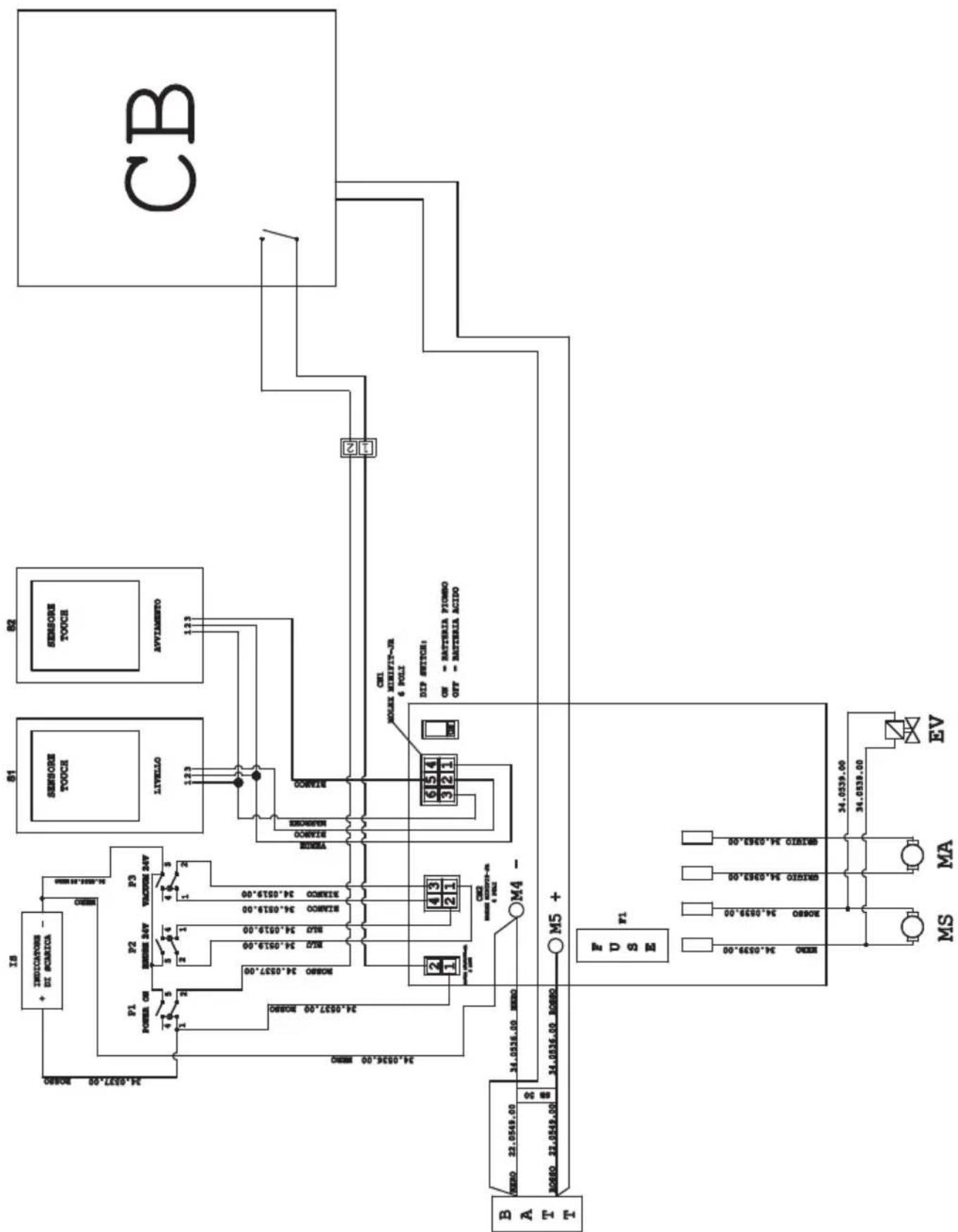
WIRING DIAGRAM
TOUCH BASIC
flowchart
graph TD
    CB["CB"] -->|2| TOC1["TOCS FOCS"]
    CB -->|1| TOC2["TOCS FOCS"]
    TOC1 -->|0.0| M4["M4"]
    TOC2 -->|0.0| M5["M5"]
    M4 -->|34.0536.00 NEW| BATTB["BA T T"]
    M5 -->|34.0536.00 NEW| EV["EV"]
    M4 -->|34.0536.00 NEW| MA["MA"]
    M5 -->|34.0536.00 NEW| MS["MS"]
    M4 -->|34.0536.00 NEW| VOUT["OUT"]
    M5 -->|34.0536.00 NEW| VOUT
    M4 -->|34.0536.00 NEW| M1["ME"]
    M5 -->|34.0536.00 NEW| M2["ME"]
    M4 -->|34.0536.00 NEW| M3["ME"]
    M5 -->|34.0536.00 NEW| M4["ME"]
    M4 -->|34.0536.00 NEW| VOUT
    M5 -->|34.0536.00 NEW| VOUT
    M4 -->|34.0536.00 NEW| M1
    M5 -->|34.0536.00 NEW| M2
    M4 -->|34.0536.00 NEW| M3
    M5 -->|34.0536.00 NEW| M4
    M4 -->|34.0536.00 NEW| VOUT
    M5 -->|34.0536.00 NEW| VOUT
    M4 -->|34.0536.00 NEW| VOUT
    M5 -->|34.0536.00 NEW| VOUT
    M4 -->|34.0536.00 NEW| VOUT
    M5 -->|34.0536.00 NEW| VOUT
    M4 -->|34.0536.00 NEW| VALL["AVTIAMENTO"]
    M5 -->|34.0536.00 NEW| VALL
    M4 -->|34.0536.00 NEW| VALL
    M5 -->|34.0536.00 NEW| VALL
    M4 -->|34.0536.00 NEW| VOUT
    M5 -->|34.0536.00 NEW| VOUT
    M4 -->|34.0536.00 NEW| VOUT
    M5 -->|34.0536.00 NEW| VOUT
    M4 -->|34.0536.00 NEW| VNET["VE"]
    M5 -->|34.0536.00 NEW| VNET
    M4 -->|34.0536.00 NEW| VNET
    M5 -->|34.0536.00 NEW| VNET
    M4 -->|34.0536.00 NEW| VOUT
    M5 -->|34.0536.00 NEW| VOUT
    M4 -->|34.0536.00 NEW| VOUT
    M5 -->|34.0536.00 NEW| VOUT
    M4 -->|34.0536.00 NEW| VMT["VA"]
    M5 -->|34.0536.00 NEW| VMT
    M4 -->|34.0536.00 NEW| VMT
    M5 -->|34.0536.00 NEW| VMT
    M4 -->|34.0536.00 NEW| VOUT
    M5 -->|34.0536.00 NEW| VOUT
    M4 -->|34.0536.00 NEW| VOUT
    M5 -->|34.0536.00 NEW| VOUT
    M4 -->|34.0536.00 NEW| VNT["VE"]
    M5 -->|34.0536.00 NEW| VNT
    M4 -->|34.0536.00 NEW| VNT
    M5 -->|34.0536.00 NEW| VNT
IS ......Discharge indicator
CN 1 ......6-pin connector sensors board
CN 2 ......4-pin connector switches board
CN 3 .. 2-pole connector for S-V switchboard
F1 ......Fuse 50A
MA......Vacuum engine
MS .... Brush engine
EV......Solenoid
P1....Main switch
P2 Brush switch
P3 Suction switch
S1 ...... Recovery level touch sensor
S2.....Touch sensor handle
BATT ...... Battery
CB Battery charger
ON= Batteria Gel...... ON= Gel battery
OFF= Batteria acido ......OFF= Acid battery
ROSSO....Red
BLU Blue
GRIGIO....Grey
BIANCO ...... White
NERO ....Black
MARRONE .... Brown
VERDE ...... Green
Cher client,
Fig. C = position correct
Touch basic......ES-16
Datos técnicos
P1 Interruptor principal
P2....Interruptor del cepillo
PROBLEMAS - CAUSAS - SOLUÇÕES
PROBLEEM - OORZAAK - OPLOSSING
CN 1 ......6-pins connector sensoren board
CN 2 .... 4-pins connector schakelaars board
CN 3 ......2-polige connector kaart schakelaars en m.k.
F1 ......Zekering 50A
MA......Vacuum motor
MS......Borstel motor
EV......Solenoid
2.1 POPIS STROJE (Obr. 1)
6.2 PRACOVNÍ CYKLUS PŘÍKLAD (Obr. 9)
230)Two-1000 (230) Two-1000 (230) Two-1000 (230) Two-1000 (230) Two-1000 (230) Two-1000 (230) Two-1000 (230) Two-1000 (230) Two-1000 (230) Two-1000 (230) Two
Professional Cleaning Machines Since 1968
DEALER
GHIBLI & WIRBEL S.p.A.
Registered office:
Via Enrico Fermi, 43 - 37136 Verona (VR) - Italy
Headquarters:
- Contents
- Technical data......EN-3
- Troubleshooting....EN-14
- INTRODUCTION
- DANGER:
- GETTING TO KNOW THE MACHINE (Fig. 1)
- UNPACKING (Figg. 1-2)
- 3.1.a - Standard machine equipment (Fig. 3)
- ASSEMBLING THE COMPONENTS
- 4.1.a - Wiper assembly (Fig. 4)
- N.B.:
- 4.1.b - Brush assembly (Fig. 5)
- HAZARD:
- 4.1.c - Installing and connecting the batteries (Fig. 6)
- WARNING:
- CHECK THAT THE RECOVERY TANK AND THE CLEAN WATER TANK ARE EMPTY.
- CHARGING THE BATTERY
- NOTE:
- 5.1.a - Charging the battery using the on board battery charger (if present) (Fig. 7)
- 5.1.b - Charging the battery using an external battery charger (Fig. 8)
- CONTROL PANEL (Fig. 9)
- 20) Sensor for starting brush/es rotation
- 45) Main switch " ⏻"
- 46) Aspirator start switch "
- 47) Switch for enabling the brush / sole-noid
- 4) Water quantity adjustment tap
- 48) Status indicator battery discharge
- WORKING CYCLE EXAMPLE (Fig. 9)
- FILLING THE TANK
- (Fig. 11)
- OPERATION (Fig. 1)
- 8.1.a - Checks before use
- 8.1.b - Preparing the machine and choosing the cycle (Fig. 9-12)
- Working cycle:
- Drying only cycle:
- Brushing only cycle:
- Washing, brushing cycle:
- Washing, brushing, drying cycle:
- 8.1.c - Using the machine (Fig. 1)
- 8.1.d - End of use and switching off (Fig. 9-13)
- 8.1.e - Maximum recovery tank water level alarm (Fig. 14)
- DRAINING THE RECOVERY WATER
- MAINTENANCE AND CLEANING
- OPERATIONS TO PERFORM DAILY
- 10.1.a - Emptying and cleaning the clean water tank (Fig. 16)
- 10.1.b - Cleaning the recovery water tank (Fig. 17)
- 10.1.c - Cleaning the squeegee (Fig. 4)
- OPERATIONS TO PERFORM WHEN NECESSARY
- 10.1.d - Cleaning the clean water filter (Fig. 18)
- 10.1.e - Replacing the brush (Fig. 19)
- 10.1.f - Replacing the squeegee rubber blades (Fig. 20)
- 10.1.g - Cleaning the recovery water tank (Fig. 21)
- 10.1.h - Replacing the fuses (Fig. 6-22)
- Fuse (74) - 5A
- Fuse (63) - 75A
- 10.1.i - Wiper adjustment (Fig. 23)
- Height adjustment
- Incidence adjustment
- - Battery charger and digital instrument configuration (Fig. 24)
- Standard configuration with Sonnenschein gel batteries
- Configuration for acid batteries
- TROUBLESHOOTING
- WARRANTY
- WIRING DIAGRAM
- PROBLEEM - OORZAAK - OPLOSSING
- POPIS STROJE (Obr. 1)
- PRACOVNÍ CYKLUS PŘÍKLAD (Obr. 9)
- GHIBLI & WIRBEL S.p.A.
Brand : Ghibli & Wirbel
Model : FR 30 SM 45 TOUCH
Category : Industrial cleaning machine