
VTC R 2DC E - Cooker TEKA - Free user manual and instructions
Find the device manual for free VTC R 2DC E TEKA in PDF.

| Product type | Ceramic hob |
| Brand | Teka |
| Model | VTC R 2DC E |
| Number of cooking zones | 4 |
| Control type | Rotary (knobs) |
| Power range | Positions 0 to 12 |
| Dual zone | Yes (on some models) |
| Built-in dimensions (W x D) | 560 x 490 mm |
| Minimum distance above | 650 mm |
| Compatible worktop thickness | 20, 30 or 40 mm |
| Surface material | Vitroceramic |
| Residual heat indicator | Yes |
| Power supply | 230 V / 50 Hz (estimate) |
| Recommended cleaning | Special vitroceramic products (e.g., Vitroclen), scraper |
| Installation | On TEKA oven, by approved technician |
| Technical service | TEKA (contact details in manual) |
Frequently Asked Questions - VTC R 2DC E TEKA
User questions about VTC R 2DC E TEKA
0 question about this device. Answer the ones you know or ask your own.
Ask a new question about this device
Download the instructions for your Cooker in PDF format for free! Find your manual VTC R 2DC E - TEKA and take your electronic device back in hand. On this page are published all the documents necessary for the use of your device. VTC R 2DC E by TEKA.
USER MANUAL VTC R 2DC E TEKA
natural_image
Four simple circles arranged in a 2x2 grid, no text or symbols present
natural_image
Simple geometric diagram with five circles arranged in a grid (no text or symbols)
Índice / Contents / Inhalt / Table des Matières
ES
| Installation | 26 |
| Positioning the hobs | 26 |
| Positioning the oven | 26 |
| Fixing the hob | 26 |
| Connecting the electricity | 27 |
| Joining the hob to the oven | 27 |
| Technical information | 28 |
| Use and maintenance | 29 |
| Requirements before first use | 29 |
| Ceramic hobs with controls | 29 |
| Advice on using the hotplates effectively | 30 |
| Cleaning and care | 31 |
| If something doesn't work | 33 |
DE
GB The layout may differ for the one shown in the drawings.
1 Back left cooking zone
2 Back right cooking zone
3 Front left cooking zone
4 Front right cooking zone
5 Residual heat indicators
natural_image
Technical line drawing of a mechanical assembly with no visible text or symbolsModelos E:
natural_image
Technical line drawing of a mechanical assembly with multiple components and mounting holes (no text or symbols)natural_image
Two simple geometric shapes: a large circle and a smaller circle, both overlapping with no text or symbols.natural_image
Illustration of a mechanical wrench with an arrow indicating direction (no text or symbols)
natural_image
3D rendered mechanical component with a black arrow indicating direction (no text or symbols)Cuchilla protegida Cuchilla desprotegida
natural_image
Technical line drawing of a mechanical assembly with no visible text or symbolsModelos E:
natural_image
Technical line drawing of a mechanical assembly with components and mounting holes (no text or symbols)
natural_image
Two simple geometric shapes: a large circle and a overlapping circle, both outlined in black (no text or symbols)Pilotos de calor residual
natural_image
3D rendered mechanical component with an arrow indicating direction (no text or symbols)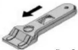
natural_image
3D rendered image of a mechanical wrench with an arrow indicating direction (no text or symbols)fig. 8
Guide to Using the Instructions Booklet
Dear customer,
We are delighted that you have put your trust in us.
We are confident that the new hob that you have purchased will fully satisfy your needs.
This modern, functional and practical model has been manufactured using top-quality materials that have undergone strict quality controls throughout the manufacturing process.
Before installing and using it, we would ask that you read this Manual carefully and follow the instructions closely, as this will guarantee better results when using the appliance.
Keep this Instruction Manual in a safe place so that you can refer to it easily and thus abide by the guarantee conditions.
In order to benefit from this Guarantee, it is essential that you submit the purchase receipt together with the Guarantee certificate.
You should keep the Guarantee Certificate or, where relevant, the technical datasheet, together with the Instruction Manual for the duration of the useful life of the appliance. It has important technical information about the appliance.
Safety instructions
Before first use, you should carefully read the installation and connection instructions.
These hob models may be installed in the same kitchen furniture units as TEKA brand ovens.
For your safety, installation should be carried out by an authorised technician and should comply with existing installation standards. Likewise, any internal work on the hob should only be done by TEKA's technical staff, including the change of the flexible supply cable of the appliance.
Please note:
When the hotplates are in operation or have recently been in operation, some areas will be hot and can burn. Children should be kept well away.
⚠️ If the glass ceramic breaks or cracks, the hob should immediately be disconnected from the electric current in order to avoid the risk of electric shock.
Installation
Important
INSTALLATION AND SETUP SHOULD BE CARRIED OUT BY AN AUTHORISED TECHNICIAN IN LINE WITH CURRENT INSTALLATION STANDARDS.
Positioning the hobs
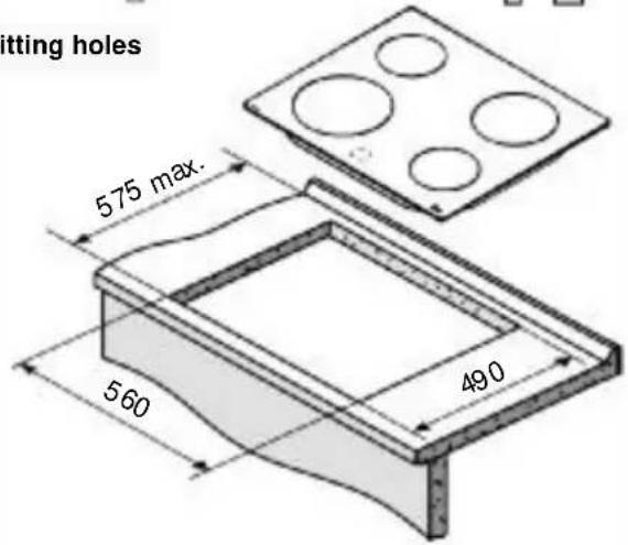
Depending on the model to be installed, an opening with the dimensions shown in figure 1 will be cut into the unit's worktop.
The system for fixing the hob is intended for use with kitchen units with a thickness of 20, 30 and 40 mm.
The hobs described in this manual can only be installed with Teka ovens models E or ES.
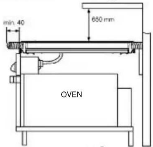
The minimum distance between the surface supporting the cooking pans and the lower part of the kitchen unit or the hood located above the hob should be 650 mm. If the hood's installation instructions recommend that the gap is greater than this, you should follow this advice.
The unit where the hob and oven will be located will be suitably fixed.
The glues used in manufacturing the kitchen unit and in the adhesive on the decorative laminate of the worktop surface should be made to tolerate temperatures of up to 100^ C.
TEKA assumes no responsibility for any malfunction or damage caused by faulty installation.
During installation, care must be taken not to break the glass.
PLEASE REMEMBER THAT THE GUA-
Minimum distances to walls
fig. 1
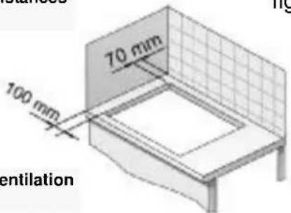
Minimum ventilation distances
Fitting holes
RANTEE DOES NOT COVER THE GLASS IF IT SUFFERS A VIOLENT BLOW OR IF IT IS USED IMPROPERLY.
Positioning the oven

See the corresponding manual.
Fixing the hob
When the gap has been properly sized, the sealing washer should be put on the
lower part of the hob. Silicone should not be applied between the glass and the unit worktop because if it becomes necessary to remove the hob from its position, the glass could break when trying to detach it.
fig. 2
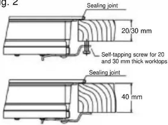
Position the clips as shown in the diagram, fastening them to the openings in the lower part of the body using the screws provided.
For worktop thicknesses of 30 mm. or less, use the self-tapping screws that are provided as a fastening accessory - put them into the clip's round hole. This hole will be threaded as the screw is inserted into it, and this should be done before fixing the clip to the worktop.
Connecting the electricity
Before connecting the hob to the electric mains, check that the voltage and frequency of the mains matches what is shown on the hob's rating plate, which is located lower down, and on the guarantee certificate or, where appropriate, the technical datasheet supplied, which should be kept together with this manual.
The electric connection is made via an omnipolar switch or plug where accessible, which is suitable for the intensity to be tolerated and which has a minimum gap of 3 mm between its contacts, which will ensure disconnection in case of emergency or when cleaning the hob.
The connection should include correct earthing, in compliance with current norms.
Avoid that the cabling remain in contact with neither the casing of the hotplate nor that of the oven.
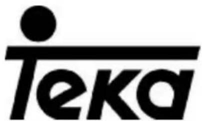
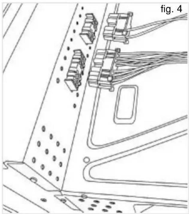
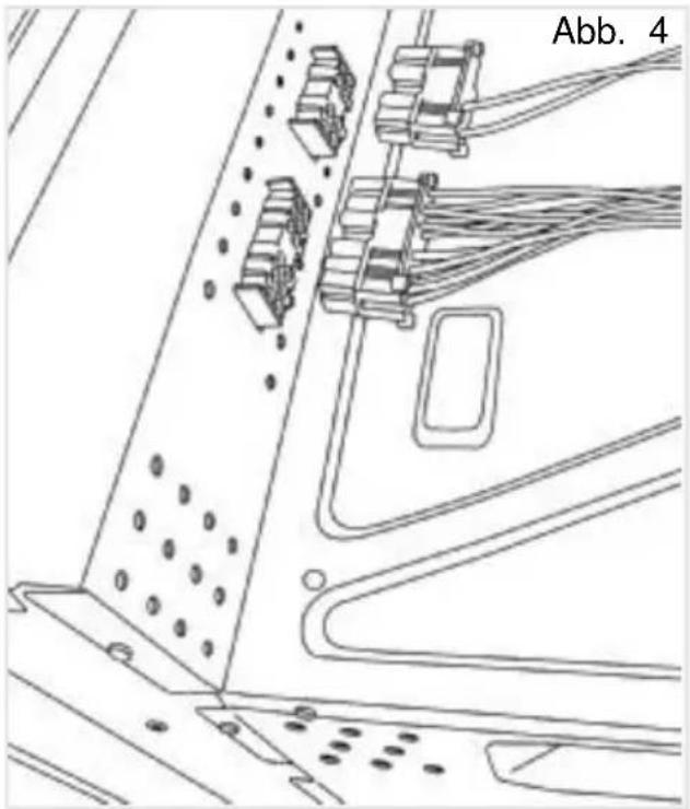
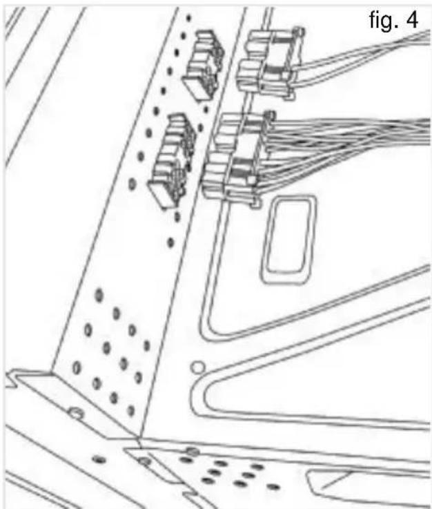
Joining the hob to the oven
1 Disconnect the electricity.
2 Partially place the oven in its position.
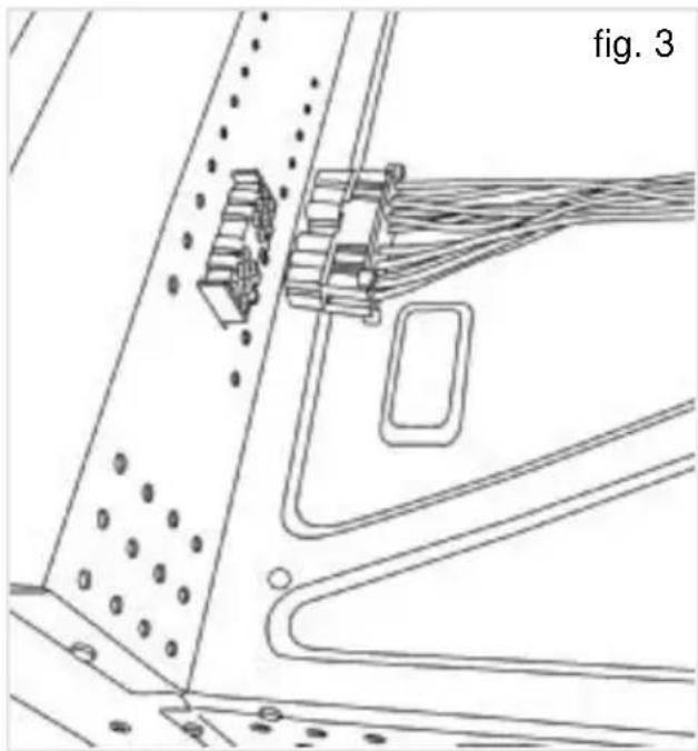
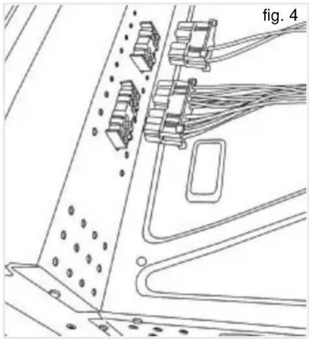
3 Plug in the connection(s) between the cooker and the oven (see fig. 3 and 4) to connect both appliances. Make sure the connectors fit completely in its sockets and the intersection haven't caused the exit of any of the terminals. To check this, pull slightly the cables, one by one, making sure they have all kept in.
4 Finish inserting the oven into its definitive position.
Rear view of the oven.
ES models:
natural_image
Technical line drawing of a mechanical assembly or structural component, showing components like a bracket and housing (no text or symbols)E models:
natural_image
Technical line drawing of a mechanical assembly with components and mounting holes (no text or symbols)Technical information
Hob characteristics on device rear part.

The instruction manual indicates how the oven must be positioned as well as how the electrical connectors must be set up. Before accessing the interior of the appliance, it must be disconnected from the power outlet.
Use and Maintenance
Special requirements before first use
Before connecting the hob to the electric mains, check that the voltage and frequency of the mains matches what is shown on the hob's rating plate, which is located lower down, and on the guarantee or, where appropriate, the technical datasheet supplied, which should be kept together with this manual.
The apparatus is not designed to be used by people (including children) with reduced physical, mental or sensory abilities. It should also not be used by people that do not have experience handling the apparatus or who do not have knowledge of the apparatus, unless they are supervised by a person who is in charge of their safety.
Children should not be allowed to play with the apparatus.
This appliance is not designed to work through an external timer (not incorporated into the appliance itself) or a separate remote control system.
Ceramic hobs with controls instructions
Each of the glass ceramic hob's heating elements is connected to a power regulator that controls the operating and stoppage time of each of them (more or less heat). (See fig. 5)
Each power regulator control knob has numbering from "0" to "12".
At position "0" the hob does not operate, at position "1" there is not much operating time but a great deal of stoppage time. With the remaining control knob positions, the operating time increases while the stoppage time decreases, until at position "12" where operation is continuous, only cutting off when the warm hotplate's thermostat cuts in to turn off the power when the maximum permitted temperature is reached.
Before turning on one of the hob's heating elements, you should identify the corresponding control. To this end, it is shown beside each control which heating element it corresponds to.
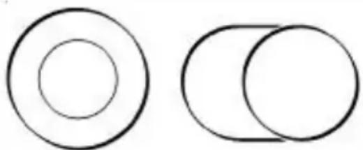
DOUBLE CIRCUIT INSTRUCTIONS (view fig. 6)
The double circuit heating elements are hotplates made up of two mutually independent heating elements, and they are controlled by a power regulator that allows the smaller, inside ring to be turned on, or both inside and outside at the same time. To only have the inside ring turned on, turn the control knob clockwise and set it to the position you require. To turn on the whole hotplate, set the control to position "12"
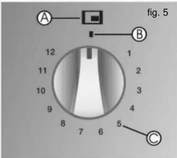

Indicator of the operation of the hotplate

Position of the control button in standby position

Power level indicator
and go on turning, gently, until it goes past "0" and you hear a "CLICK". Then set the control to the position required. When the whole hotplate is turned on, and you only want to have the smaller ring working, set the control to ZERO and then turn it on again.
Whether only one ring is turned on, or both, you can regulate the temperature by setting the control to intermediary positions, just as with the normal and halogen hobs described in the previous paragraph.
With double circuit regulators, when the control is set to “0” it may only be turned clockwise, as there is a catch which prevents you moving from “0” to “12” and vice-versa.
fig. 6
natural_image
Two simple geometric shapes: a large circle and a smaller overlapping circle, both without any text or symbols.RESIDUAL HEAT INDICATORS
When a heating area reaches a temperature of more than 60 ± 15^ the corresponding residual heat indicator comes on, and stays on - even if the control is set to zero - until the temperature drops. However, special attention should be paid to the temperature of the cooking area because there is a possibility, albeit remote, that the indicator will fail and that the temperature in that area will not be shown.
Advice on using the hotplates effectively
In order to achieve the best results from cooking, the following guidelines should be followed:
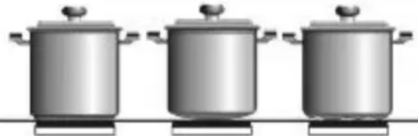
* Use pans with a flat base, as the greater the surface contact between the pan and the glass, the greater will be the heat transmission. Figure 7 shows how pans that are dented or concave have a smaller contact surface.
fig. 7
natural_image
Three identical stainless steel cooking pots arranged horizontally (no text or symbols visible)Right Wrong
Wrong
* We recommend the use of heavy pans so that the base is more difficult to dent.
* The use of pans with a diameter which is smaller than that indicated in the heating area is not recommended.
* Make sure that the pans are well centred on the outlines shown on the heating area.
* Dry the pans' bases before putting them on the glass ceramic hob.
* Do not leave any plastic object or utensil, or any aluminium foil, lying on the glass hob.
* Do not drag pans with corners or edges that could damage the glass.
* Do not use the glass ceramic hob without a pan on the area that is switched on.
* Do not cook with plastic pans.
* Pans should be made of a material which is heat-resistant so that they do not melt on the glass.
* The glass will tolerate bangs from big pans that do not have sharp edges. Be careful with impacts from small, sharp instruments.

Avoid spilling sugar, or products mining sugar, on the glass, since
these may react with the glass and damage the surface.
Cleaning and care
To maintain the glass ceramic hob in good condition, it should be cleaned with suitable products. The glass ceramic hob should be cleaned each time it is used, when it is either lukewarm or cool. This makes cleaning easier and avoids dirt accumulating through repeated use.
Never use aggressive cleaning products or products that can scratch the surfaces (the table below shows various common products that may be used). Neither should steam-based appliances be used to clean the hob.
CLEANING AND CARE THE GLASS
The degree of soiling should be taken into account when cleaning, and the items and products used should vary according to this.
Light soiling
Light, non-sticky, soiling can be cleaned with a damp cloth and a soft detergent or warm, soapy water.
Heavy soiling
Serious dirt and grease should be cleaned using an agent specially made for glass ceramic (for example, Vitroclen). Please follow the manufacturer's instructions.
Sticky stains that have been burned in can be removed by using a scaper with a razor blade.
Rainbow colouring: Caused by pans that have dry bits of grease on their base or when grease gets between the glass and the pan while cooking. Can be removed from the surface of the glass using a nickel scourer with water or with a special glass ceramic cleaner (for example, Vitroclen).
Plastic objects, sugar, or food with a high sugar content that are melted onto the hob should be removed immediately while hot, using a scraper.
When the glass' colour changes.
This does not affect its effectiveness or stability, and is generally caused by inadequate cleaning or by poor-quality pans.
Metallic sheens are caused by metal pans

RECOMMENDED CLEANING PRODUCTS
| Product | Should it be used to clean... | |
| ... the glass? | ... the surround? | |
| Soft and liquid detergents | YES | YES |
| Aggressive or powder detergents | NO | NO |
| Special glass ceramic cleaning agents (e.g. Vitroclen) | YES | YES |
| Grease-removing sprays (ovens, etc.) | NO | NO |
| Soft cloths | YES | YES |
| Kitchen towels | YES | YES |
| Kitchen cloths | YES | YES |
| Nickel scourers (never use dry) | YES | NO |
| Steel scourers | NO | NO |
| Hard synthetic scourers (green) | NO | NO |
| Soft synthetic scourers (blue) | YES | YES |
| Glass scrapers | YES | NO |
| Liquid polish for domestic appliances and/or glass | YES | YES |
sliding over the glass. They can be removed by thorough cleaning with a special, glass ceramic cleaning agent (for example, Vitroclen), although it may be that the cleaning needs to be repeated more than once.
Worn trim is the result of using abrasive cleaning products or pans with uneven bases which wear down the serigraphy.
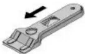
⚠️ Take great care when using the glass scraper. The blade can cause injury!
Only use the blade on the glass ceramic surface - avoid the body of the scraper coming into contact with the glass, since this could scratch the glass ceramic.
⚠️ Use blades that are in perfect conditions, and change the blade as soon as it shows any sign of wear.
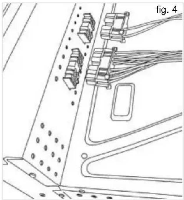
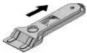
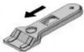
When you finish using the scraper, fold it away and cover it well up. (See fig. 8).
Using the scraper
fig. 8
natural_image
3D rendered mechanical component with an arrow indicating direction (no text or symbols)Protected blade
natural_image
3D illustration of a mechanical wrench with an arrow indicating direction (no text or symbols)Unprotected blade
⚠️ Pans may stick to the glass if something has melted between them. Do not attempt to unstick the pan when it is cold - you could break the glass ceramic.
Do not stand on the glass or lean on it, for it might break and cause
injury. Do not put any objects down on the glass.
CLEANING AND CARE THE FRAME
Clean dirt off using a damp cloth or warm, soapy water. With stubborn stains, use a special glass ceramic cleaning agent, or a liquid polish for domestic appliances. Rub the product on without diluting it, leave it to work, and then wipe off with a dry cloth. Do not use metal scourers or hard synthetics.
TEKA INDUSTRIAL S.A. reserves the right to alter its manuals in any way it deems necessary or useful while not altering their basic characteristics.

The symbol 📄 on the product or on its packaging indicates that this product may not be treated as household waste. Instead it shall be handed over to the applicable collection point for the recycling of electrical and electronic equipment. By ensuring this product is disposed of correctly, you will help prevent potential negative consequences for the environment and human health, which could otherwise be caused by inappropriate waste handling of this product, please contact your local city office, your household waste disposal service or the shop where you purchased the product.
If something doesn't work
Before calling the Technical Service, please make the following checks:
| Fault Possible cause Possible solution | ||
| Neither the hotplates nor the pilot lights are working | ||
| The oven's power line is disconnected. | Connect the oven's cable to the power outlet. | |
| The connecting cable between the cooker and the oven is disconnected. | Connect the cable to the oven. | |
| The pan is sticking to the glass | ||
| Something has melted between the pan and the glass. | Set the hotplate to full power and try to uns-tick it. | |
| Pans with aggressive bases. | Check the bases of your pans and do not slide them across the glass. | |

natural_image
Technical line drawing of a mechanical assembly or structural component, showing internal components and connection lines (no text or symbols)Modelle E:
natural_image
Technical line drawing of a mechanical assembly with components and mounting holes (no text or symbols)natural_image
Two simple geometric shapes: a large circle and a smaller circle, both overlapping with no text or symbols.natural_image
Three identical stainless steel cooking pots on a stove (no text or symbols visible)natural_image
3D rendered mechanical component with an arrow indicating direction (no text or symbols)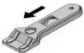
natural_image
3D illustration of a mechanical wrench with an arrow indicating direction (no text or symbols)natural_image
Technical line drawing of a mechanical assembly with no visible text or symbolsModèles E:
natural_image
Technical line drawing of an electrical panel layout with connectors and wiring (no text or symbols)
Information technique
natural_image
Two simple geometric shapes: a large circle and a smaller circle, both outlined in black (no text or symbols)INDICATEURS DE CHALEUR RÉSIDUELLE
natural_image
Three identical stainless steel cooking pots arranged horizontally (no text or symbols visible)Bien Mal
Mal
natural_image
Mechanical wrench tool with directional arrow indicating movement (no text or symbols)Lame bloquée
natural_image
3D illustration of a mechanical wrench with an arrow indicating direction (no text or symbols)Lame sortie
Teka Industrial, S.A:
Cajo, 17
39011 Santander
Cantabria - ESPAÑA
Tel.: 34-942 35 50 50
Fax: 34-942 34 76 94
http://www.teka.net

- Índice / Contents / Inhalt / Table des Matières
- ES
- DE
- Pilotos de calor residual
- Guide to Using the Instructions Booklet
- Safety instructions
- Please note:
- Installation
- Important
- Positioning the hobs
- Positioning the oven
- Fixing the hob
- Connecting the electricity
- Joining the hob to the oven
- E models:
- Technical information
- Use and Maintenance
- Special requirements before first use
- Ceramic hobs with controls instructions
- DOUBLE CIRCUIT INSTRUCTIONS (view fig. 6)
- RESIDUAL HEAT INDICATORS
- Advice on using the hotplates effectively
- Cleaning and care
- CLEANING AND CARE THE GLASS
- Light soiling
- Heavy soiling
- When the glass' colour changes.
- CLEANING AND CARE THE FRAME
- If something doesn't work
- Information technique
- INDICATEURS DE CHALEUR RÉSIDUELLE
- Teka Industrial, S.A:
Brand : TEKA
Model : VTC R 2DC E
Category : Cooker