
A2004 - Marine navigation electronics SIMRAD - Free user manual and instructions
Find the device manual for free A2004 SIMRAD in PDF.

| Product Type | Autopilot Display and Control Unit |
| Brand | Simrad |
| Model | A2004 |
| Dimensions (without bracket) | 177 x 115 x 56 mm |
| Weight (without accessories) | 0.51 kg |
| Power Supply | 12 V (10.8 - 15.6 V) |
| Power Consumption | 1.62 W (standby) / 2.97 W (max backlight) |
| Display | 4.1 inches LCD TFT, 320 x 240 pixels, >600 nits |
| Mounting | Dashboard or bracket |
| Steering Modes | Standby, NFU, FU, AUTO, NoDrift, NAV, turns |
| Work Profiles | Up to 3 customizable profiles (Normal, High, Low) |
| Compatible Computers | AC70, SG05 Pro |
| Drive Interface | AD80, SD80 |
| Connectivity | NMEA 2000, USB port |
| Ingress Protection Rating | IPx7 |
| Operating Temperature | -25 °C to +65 °C |
| Cleaning | Soft cloth with water or isopropyl alcohol (50/50) |
| Safety | Does not replace a human navigator; check the heading regularly |
| Warranty | Consult website www.navico.com/commercial |
| Software Update | Via USB key on rear port |
| Number of manual pages | 94 pages (French) |
Frequently Asked Questions - A2004 SIMRAD
User questions about A2004 SIMRAD
0 question about this device. Answer the ones you know or ask your own.
Ask a new question about this device
Download the instructions for your Marine navigation electronics in PDF format for free! Find your manual A2004 - SIMRAD and take your electronic device back in hand. On this page are published all the documents necessary for the use of your device. A2004 by SIMRAD.
USER MANUAL A2004 SIMRAD
Copyright © 2017 Navico Holding AS.
Garantie
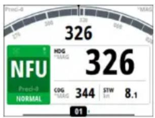
Mode Non-Follow-Up

Mode Follow-up (FU)


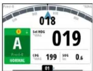
Menu rapide en mode AUTO
Mode NAV
- Clutch (Embrayage)
- Clutch (Embrayage)
natural_image
Diagram of a screwdriver with a USB cable inserted, showing the mechanism (no text or symbols present)PGN NMEA 2000 (transmission)
| Alarm/Warning Possible cause Recommended action | ||
| Active control unit missing | Autopilot computer has lost contact with active control unit. | Was active controller switched off/put to sleep?Take command with a different controller/remoteCheck/repair CAN bus cableReplace the control unit |
| Autopilot computer missing | Active control unit has lost contact with autopilot computer. | Check the network diagnostics page on the display unit.Should show few or no errorsCheck that the NMEA 2000 network is powered and terminated according to guidelinesCheck that source selection is made and that the correct autopilot computer is selectedCheck connectors and cablesCheck status LED on autopilot computer. Should blink steadily, 1 sec intervalsReplace autopilot computer |
Alarm/Warning Possible cause Recommended action
| Boat speed missing | The speed signal from the GPS or the log is missing. | ·Check device list for valid speed source·Try a new automatic source update·Check the GPS, log, and cable connections·If no speed source is available, manual speed can be entered in the “Auto” quick menu |
| CAN bus supply overload Excessive current draw. | ·Check summary unit loads·Check for short circuit/defective device on network | |
| Check heading | Jump in heading of more than 10°/second. | ·Check steering compass·Change to other heading source or monitor compass |
| Compass difference | The difference in readings between the main compass and the monitor compass exceeds the limit set for compass difference. | ·Check the operation of both compasses·If one compass is magnetic, the error may be caused by deviation change or heavy sea disturbances |
| Course difference | Compass heading is deviating too much from the track course (BWW). May be caused by extreme wind and current, combined with low speed. | ·Increase speed·Hand steer boat to align better with track and restart navigation mode |
| Cross track distance limit | XTD exceeds the set XTD limit in NAV mode. May be caused by extreme wind and current or too low boat speed. | ·Manually control the vessel |
| Alarm/Warning Possible cause Recommended action | ||
| Drive inhibit | Motor or solenoid drive electronics critically overloaded. | ·Check connectors and cables·Check that the rudder angle measurement and the actual physical rudder position corresponds·Try to hand steer the rudder and verify that the rudder can be moved freely |
| Drive not available | No drive response when requested from autopilot on Handshake port on SD80/AD80 board. | ·Check that steering gear/thruster is set for autopilot control·Check cabling to Handshake port on SD80/AD80·Make sure Handshake port on SD80/AD80 is configured for HS fixed/HS pulse |
| Drive overload | Reversible motor: motor stalls or is overloaded.Solenoids: shortage to ground or cabling damage | ·Check for possible mechanical blocking of rudder·If heavy sea at high rudder angle, try to reduce boat speed or rudder angle by steering at another heading·Make sure there is no shortage to ground or cabling damage·Disconnect cable from autopilot computer to motor, and make sure there is no alarm when trying to run in NFU mode·Check that the drive unit is appropriately dimensioned for the boat and rudder size |
Alarm/Warning Possible cause Recommended action
| Drive reference voltage missing | Reference voltage to AD80 is missing. | ·Check that the two U_CTRL dip switches on the AD80 board is set correctly (ref. cable connection label inside faulty unit)° If drive control signal is 4-20 mA current or voltage using internal ±10 V reference, switches must be set to INT.° If external ref. voltage is connected switches must be set to EXT·If external reference voltage, check cabling and measure correct voltage between U_REF+ and U_REF- on AD80 board |
| Drive unit failure | The autopilot computer has lost communication with device. | ·Check that green CPU led on the AC70 is alternating (ref. label inside unit cover for location of led)° If off , check local power supply/fuse·For AD80/SD80, check CAN supply for 9-15 V between NET-S and NET-C of SimNet plug° If LED is ok, check cabling, T-connector backbone etc° If LED is on, try to restart unit by turning power off/on |
| End of route | Activated on the active control unit when an end route waypoint name has been received from the Plotter/ECS. | ·Manually control the vessel·Select a new rout |
| Alarm/Warning Possible cause Recommended action | ||
| Engage output overload | Bypass valve or clutch is drawing excessive current. | ·Ensure there is no shortage to ground or cabling damage·Disconnect cable from autopilot computer to motor, and make sure there is no alarm when engaging FU or AUTO mode |
| EVC Com error | Lost communication with EVC system (Volvo IPS and similar). | ·Check connection with EVC engine interface. For IPS, engine must be running |
| Heading missing No data from selected compass. | ·Select a different compass source·Make a source update·Check cables and connections | |
| High drive temperature | Drive electronic temperature exceeds the set limit. | ·Switch off autopilot·Check for overload in drive unit/steering system·Check that the autopilot computer specifications matches drive unit |
| High internal temp | Internal temperature exceeds the set limit | ·Switch off autopilot·Check for overload in drive unit/steering system·Check that the autopilot computer specifications matches drive unit |
| Low boat speed | Speed below set limit for acceptable course keeping (in Work profile). | ·Switch to hand steering·Adjust Work profile settings·Increase speed to acceptable maneuvering speed |
| Low CAN bus voltage CAN bus voltage < 9 V. | Check cable length, bus load and bus supply feeding pointIf possible, check if fault disappears by disconnecting some units.Check battery/charger conditionVerify mains cable has correct gauge | |
| Low supply voltage Supply voltage <10 V (12 V -15%). | ||
| Nav data missing | Navigation data from Plotter/ECS missing. | Check that route is activated on Plotter/MFDCheck device list for valid navigation sourceTry a new automatic source updateCheck cables and connections |
Alarm/Warning Possible cause Recommended action
| No rudder response No response to rudder command. | For SD80, check that port/stbd led is activated (ref label in cover for locationReplace the autopilot computer drive boardCheck connectors and cablesCheck rudder feedback transmission link (not applicable for Virtual feedback installations)Check the drive unit motor/brushesCheck for mechanical play in rudderCheck if the rudder is actually not movingCheck that the rudder drive unit is powered and runningCheck for other mechanical issues between autopilot computer and rudder | |
| Off heading | The vessel heading is outside set off heading limit. May be caused by extreme weather conditions, and/or too slow speed. | Check steering parameters (Rudder, Autotrim, Seastate filter)Increase response/rudder valueIncrease boat speed, if possible, or steer by handWait and see if autopilot is able to bring vessel back on course. |
| Override | EVC override via SG05 Pro, override via SD80/AD80 Handshake or override via SD80/AD80 RUD UI port. | If unintended warning, make sure override handle is not being activated by loose objectsCheck cabling and override switches connected to Handshake port of SD80 or AD80 board |
| Alarm/Warning Possible cause Recommended action | ||
| Position data missing Position | data from the GPS is missing. | ·Check that the GPS antenna has a clear view of the sky·Check device list for valid position source·Try a new automatic source update·Check cables and connections·Check that the GPS antenna is not covered by ice, snow or any other objects weakening the signals from the satellites |
| Rudder data missing | Rudder angle signal to autopilot computer is missing. | ·If several rudder angle sensors, check which port on the board that is set up for use·If the missing sensor is connected to an autopilot computer, check cabling·If missing sensor is a CAN device, check network connection·Check mounting is correct and that the center position of the feedback lines up with the center position of the rudder and that the rudder movement is within the operational range of the feedback·In the case of Frequency feedbacks, and long cable runs, external electromagnetic disturbance may affect the signal in rare and extreme cases |
| Rudder limit | The set rudder limit is reached or exceeded. Might be caused by disturbance to compass (waves), speed log, sharp turn or improper parameter setting. | ·Notification only |
Alarm/Warning Possible cause Recommended action
| Thruster inhibited | The vessel speed exceed the set limit for when the thruster can be used.The Thruster inhibit limit will only apply when speed source is Log or SOG, not if the speed is set. | • Notification only, reduce speed to reactivate thruster• Adjust Thruster inhibit limit settings |

SIMRAD
Brand : SIMRAD
Model : A2004
Category : Marine navigation electronics