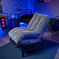
Convertible 2110901 - Gaming chair X Rocker - Free user manual and instructions
Find the device manual for free Convertible 2110901 X Rocker in PDF.


| Product type | Convertible gaming chair |
| Brand | X Rocker |
| Model | Convertible 2110901 |
| Intended use | Domestic, for video games and relaxation |
| Dimensions (approximate) | Height: 120 cm, Width: 65 cm, Depth: 70 cm |
| Weight (approximate) | 25 kg |
| Maximum supported weight | 120 kg |
| Materials | Steel frame, foam padding, faux leather upholstery |
| Features | Padded seat, reclining backrest, padded armrests |
| Assembly required | Yes, estimated time: 1.5 hours, recommended for 2 people |
| Care and cleaning | Clean with a soft cloth and mild cleaner. Avoid excess water. |
| Safety | Do not let children climb or play on the chair. Keep fingers away from mechanisms. |
| Spare parts | Available from the manufacturer. Do not substitute parts. |
| Repairability | Disassemblable and reassemblable for moving. Contact customer service for parts. |
| Warranty | Refer to the warranty document provided with the product. |
| Customer service | Phone: 866-969-2603 |
Frequently Asked Questions - Convertible 2110901 X Rocker
User questions about Convertible 2110901 X Rocker
0 question about this device. Answer the ones you know or ask your own.
Ask a new question about this device
Download the instructions for your Gaming chair in PDF format for free! Find your manual Convertible 2110901 - X Rocker and take your electronic device back in hand. On this page are published all the documents necessary for the use of your device. Convertible 2110901 by X Rocker.
USER MANUAL Convertible 2110901 X Rocker
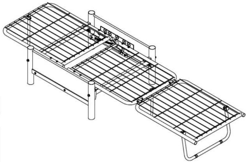
| Dimensions | |
| Closed | Extended |
| Width - 36.2inDepth - 25.5inHeight - 29.3in | Width - 76.2inDepth - 25.5inHeight - 12in |
Need Help?
Email: support@xrockergaming.com
Phone: 866-969-2603
www.xrockergaming.com
IMPORTANT: You must keep your original retail receipt as proof of purchase.
Read Before Beginning Assembly
- Call 866-969-2603 if you need assistance.
- Work in a spacious area and near where the unit will be used, preferably on a carpet, or use a piece of the cardboard packaging to protect your floor and product.
- Recommended # of people needed for assembly: 2 (however it is always better to have an extra hand).
• Estimated assembly time is 1.5 hours. - Make sure all parts are included. Most parts are labeled or stamped on the raw edge.
- Read each step carefully. It is very important that each step of the instructions is performed in the correct order. If these steps are not followed in sequence, assembly difficulties will occur.
Caution
- This product is designed for home use and not intended for commercial use.
- This product contains small components. Please ensure that they are kept away from small children.
- Clean the product with a soft damp cloth. DO NOT use harsh chemicals or abrasive cleaners.
Handy Hints
- Move your new furniture carefully, with two people lifting and carrying the unit to its new location.
- Your furniture can be disassembled and reassembled to move.
- Assemble all parts and bolts loosely during assembly, only once the product is complete should you fully tighten the bolts
- Regularly check and ensure that all bolts and fittings are tightened properly.
WARNINGS
- DO NOT Allow children to climb or play on the unit. Failure to comply could result in severe injury.
- Keep hands clear from Mechanisms installed on the Arms.
- Do not use substitute parts. Contact the manufacturer or dealer for replacement parts.
- The use of water or sleep flotation mattresses is prohibited.
- Keep these instructions for future reference.
Please check you have all the panels listed below
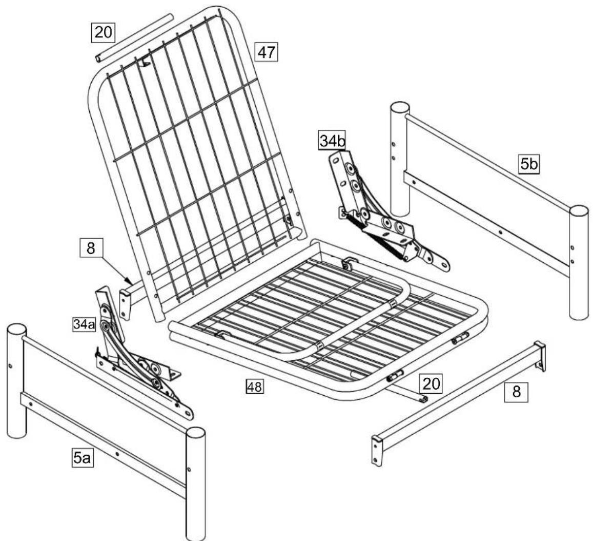
Components - Panels
Please check you have all the panels listed below
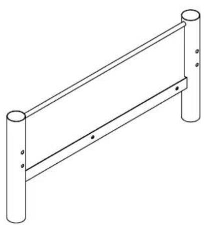
5a Left Arm x 1
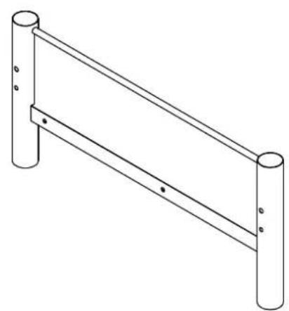
5b Right Arm x 1
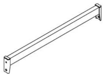
8 Side Rail x 2
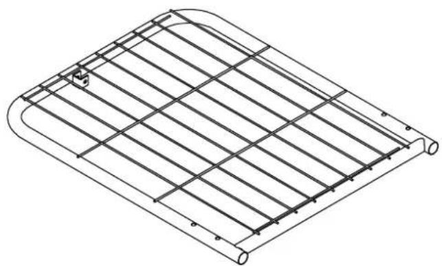
47 Back Frame x 1
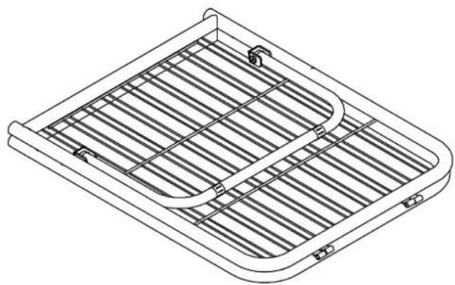
48 Seat Frame x 1

20 Leg x 2
Components - Panels
Please check you have all the panels listed below
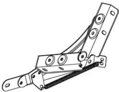
34a
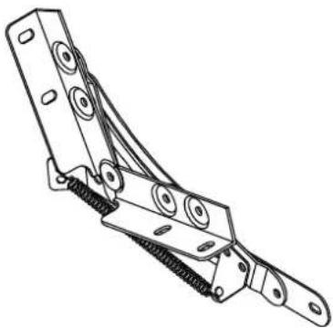
34b LeRigheMechanism1 x 1
Components - Fittings
Please check you have all the panels listed below
Note: The quantities below are the correct amount to complete the assembly. In some cases more fittings may be supplied are required.
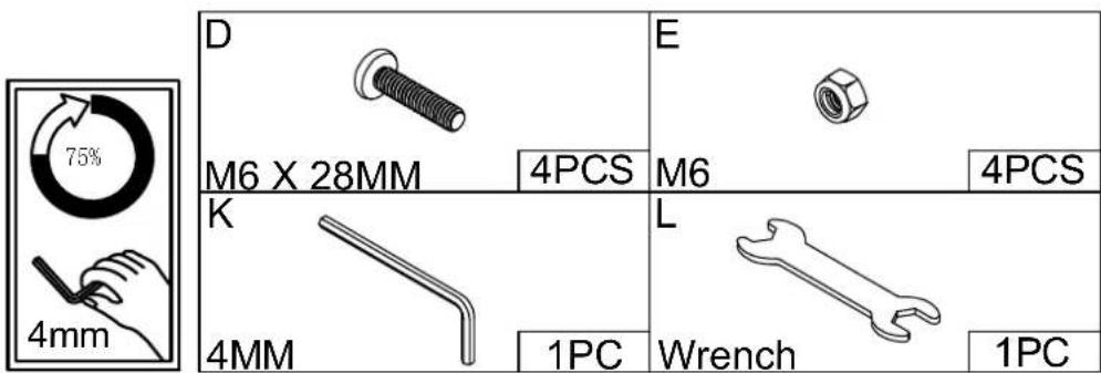
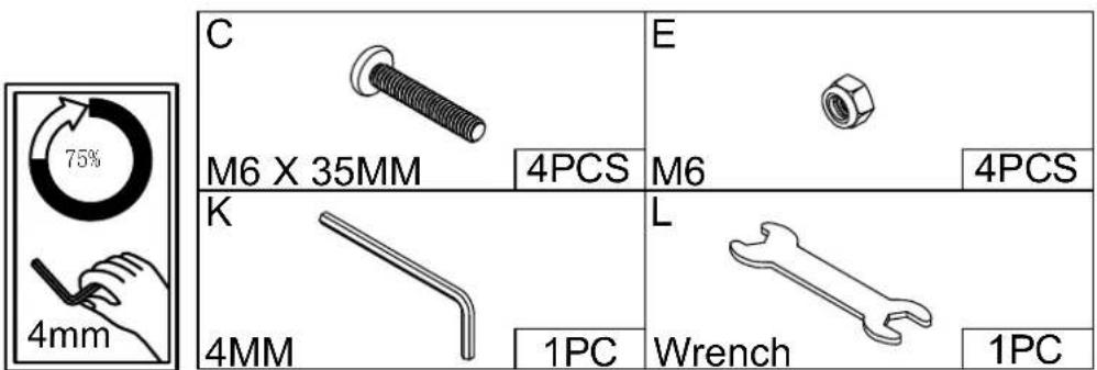
A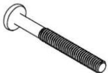 65mm M8 Bolt x 4 65mm M8 Bolt x 4 | B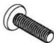 25mm M8 Bolt x 4 25mm M8 Bolt x 4 | C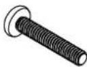 35mm M6 Bolt x 8 35mm M6 Bolt x 8 |
D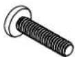 28mm M6 Bolt x 6 28mm M6 Bolt x 6 | E M6 x 12 M6 x 12 | F M8 Spring Washer x 8 M8 Spring Washer x 8 |
G M8 Metal Washer x 8 M8 Metal Washer x 8 | H M8 Plastic Washer x 8 M8 Plastic Washer x 8 | ● M6 Spring Washer x 2 M6 Spring Washer x 2 |
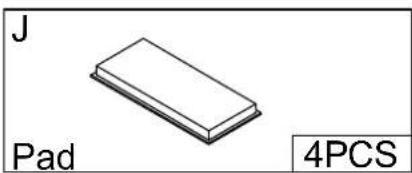
J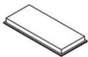 Pad x 4 Pad x 4 | K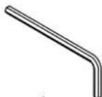 Allen Key 4mm x 1 Allen Key 4mm x 1 | L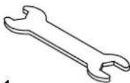 Wrench x 1 Wrench x 1 |
Tools required

Ruler/tape measure
Ruler - User this ruler to help correctly identify the screws

Assembly Instructions
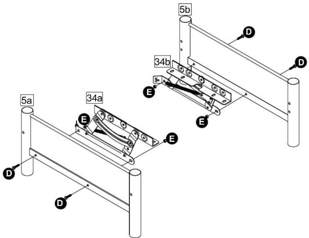
Step 1
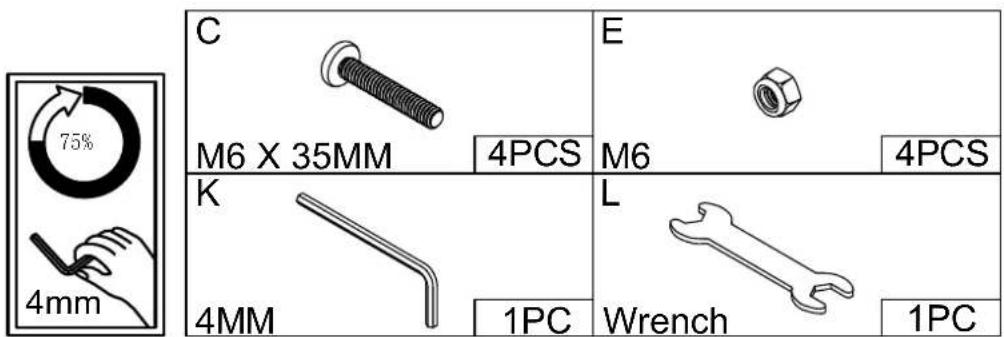
Attach Left Mechanism 34a and Right Mechanism 34b to Left Arm 5a and Right Arm 5b with D, E.
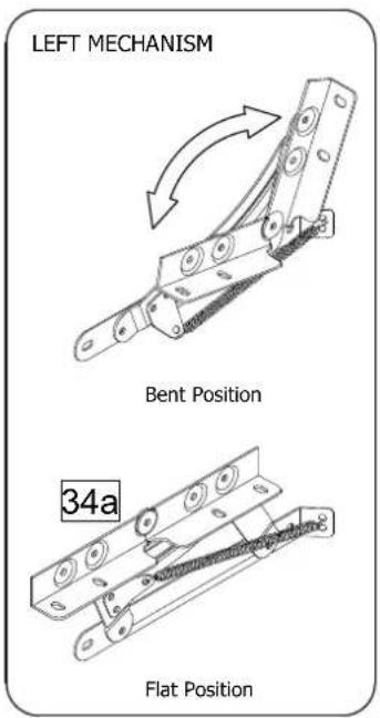
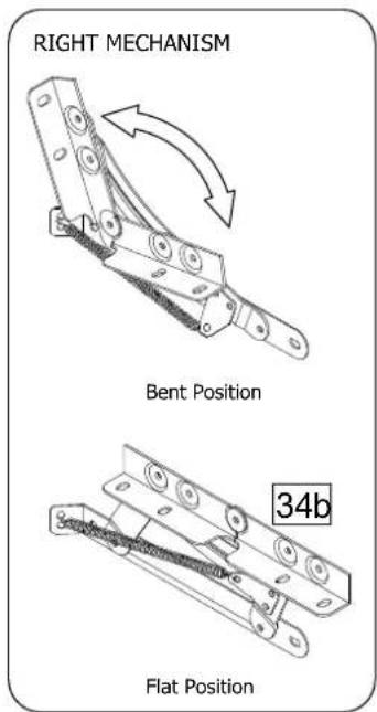

Keep hands clear from Mechanisms installed on the Arms.
Assembly Instructions
Step 2
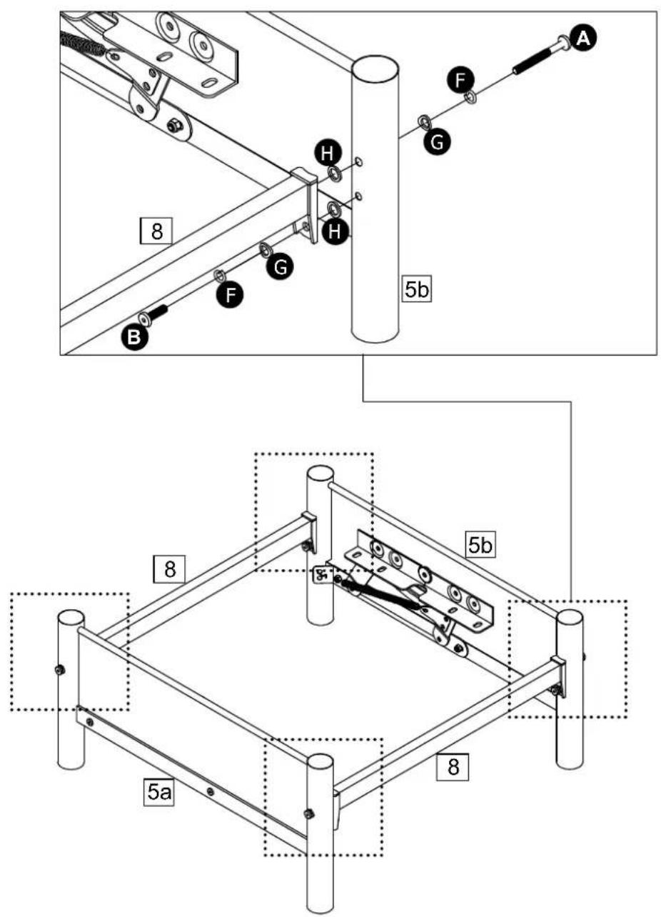
Attach Side Rail 8 x 2 to
Left Mechanism 5a and
Right Mechanism5b with
B, F, G, H and A,
F, G, H.
A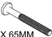 | B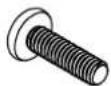 | ||
| M8 | 4PCS | M8 X 25MM | 4PCS |
F | G | ||
| M8Spring Washer | 8PCS | M8Metal Washer | 8PCS |
H | K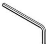 | ||
| M8Plastic Washer | 8PCS | 4MM | 1PC |
Assembly Instructions
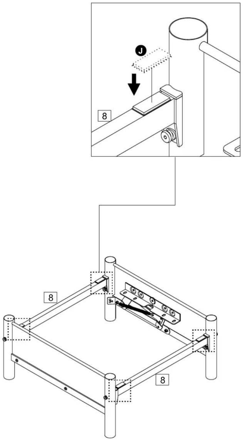
Step 3
Attach J x 4 to Side Rail 8 x 2.
Assembly Instructions
Step 4
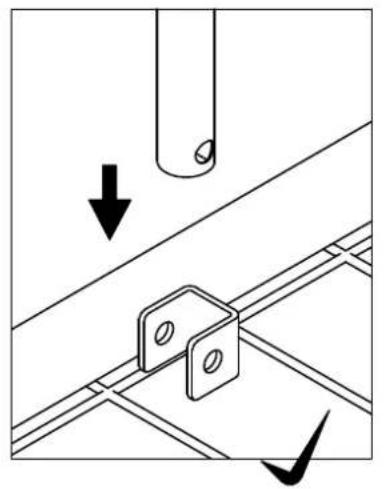
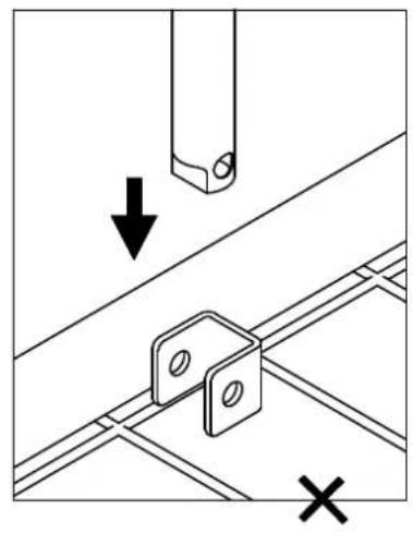
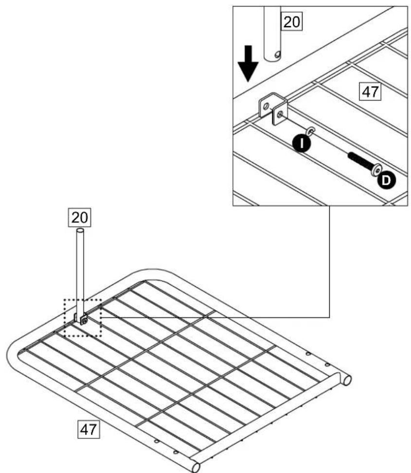
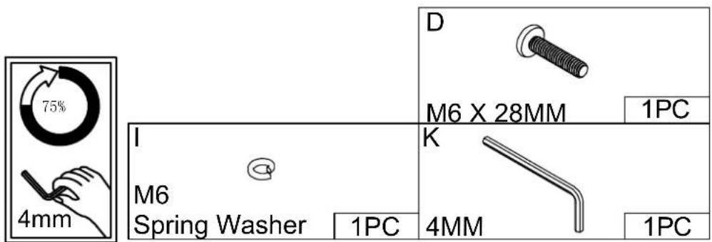
Attach Leg 20 x 1 to Back Frame 47 with D, I.
Assembly Instructions
Step 5
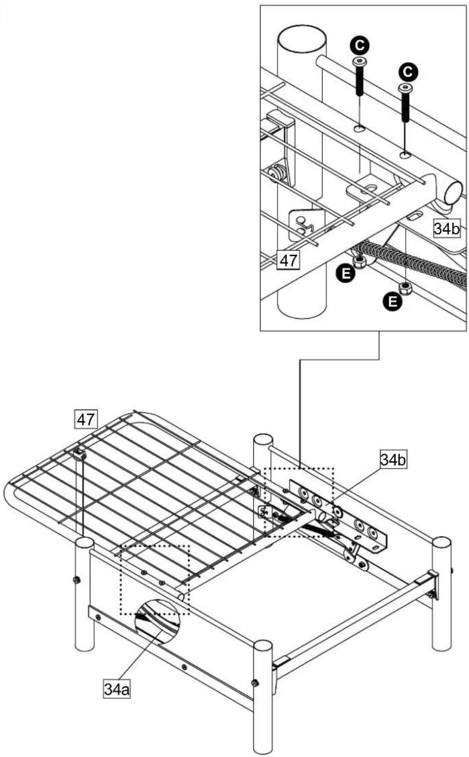
Attach Back Frame 47 to
Left Mechanism 34a and
Right Mechanism34b with

Assembly Instructions
Step 6
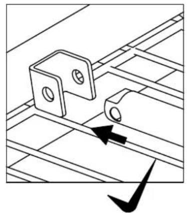
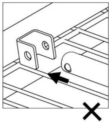
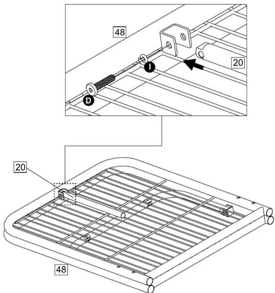
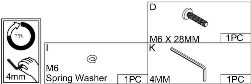
Attach Leg 20 x 1 to Seat Frame 48 with D, I.
Assembly Instructions
Step 7
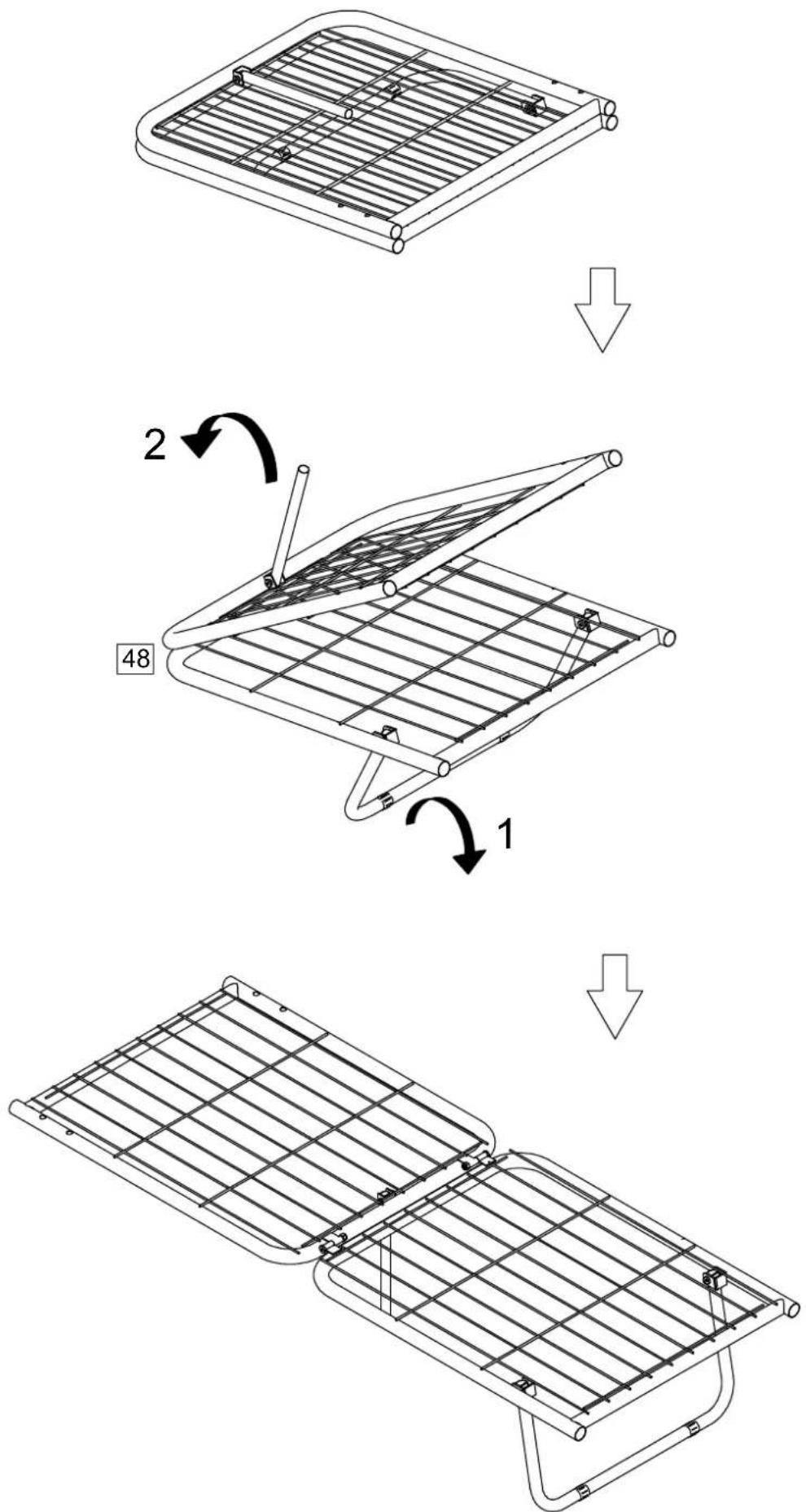
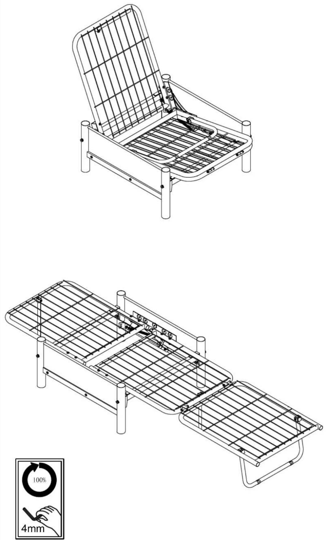
Open out Seat Frame48.
Fold out the support foot.
Open as shown.
Assembly Instructions
Step 8
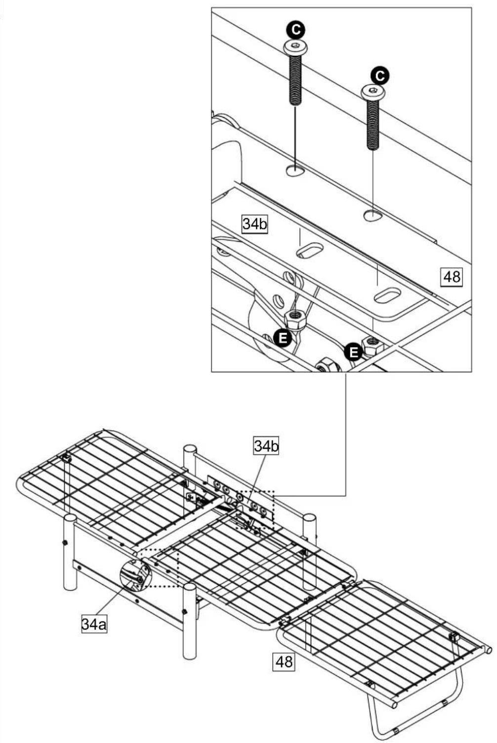
Attach Seat Frame 48 to
Left Mechanism 34a and
Right Mechanism 34b with

Assembly Instructions
Step 9
Assembly Instructions
Step 10
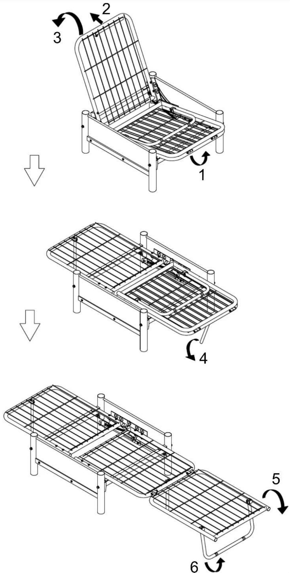
TO OPEN
1) From the front corner of the seat frame, raise the seat frame slightly.
2) At the same time, push the back frame and leg down until both frames are flat.
3) Open the support foot until it clicks into position.
4) Open out the folding seat.
5) Fold out the two main legs.

Keep hands clear of hinge area when opening and open the futon.
TO CLOSE
Fold in the main legs. Close out the folding seat.
Press the support feet. Lift the front edge of the seat frame.
Lift the back section until both frames are raised into the seating position.

Keep hands clear of hinge area when opening and closing the futon.

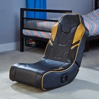
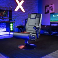

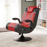
Brand : X Rocker
Model : Convertible 2110901
Category : Gaming chair