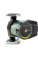
EVOSTA2 - Pump DAB - Free user manual and instructions
Find the device manual for free EVOSTA2 DAB in PDF.


| Product Type | Variable speed electronic circulator |
| Model | EVOSTA2 (without display) / EVOSTA2d (with display) |
| Brand | DAB |
| Category | Circulation pump |
| Supply voltage | 110-127 V (+/- 10%), 60 Hz |
| Protection rating | IPX5 |
| Insulation class | F |
| Liquid temperature | -10 °C to +110 °C (14 °F to 230 °F) |
| Max. ambient temperature | 40 °C (104 °F) |
| Max. operating pressure | 1.0 MPa (10 bar / 145 psi) |
| Min. operating pressure | 0.1 MPa (1 bar / 14.5 psi) |
| Max. head | 5.5 m (18 ft) |
| Max. flow rate | 3.6 m³/h (16 gpm) |
| Noise level | ≤ 43 dB(A) |
| Weight | Indicated on packaging |
| Regulation modes | Proportional pressure, constant pressure, constant curve (9 settings) |
| Motor protection | Integrated (overload, phase failure, overtemperature, over/undervoltage) |
| Additional functions (EVOSTA2d) | Dry run protection, automatic degassing |
| Display | EVOSTA2: LEDs; EVOSTA2d: graphic display (W, head, flow) |
| Maintenance | Manual venting before commissioning; maintenance by qualified personnel |
| Safety | Cut off power before intervention; wait for LEDs to turn off |
| Disposal | In accordance with local environmental standards |
Frequently Asked Questions - EVOSTA2 DAB
User questions about EVOSTA2 DAB
0 question about this device. Answer the ones you know or ask your own.
Ask a new question about this device
Download the instructions for your Pump in PDF format for free! Find your manual EVOSTA2 - DAB and take your electronic device back in hand. On this page are published all the documents necessary for the use of your device. EVOSTA2 by DAB.
USER MANUAL EVOSTA2 DAB
8.1 Mechanical installation....5
8.2 User Interface Position....6
8.3 Rotation of the user interface 7
8.4 Non-return valve.... 8
- ELECTRICAL CONNECTIONS 9
9.1 Power supply connection.... 10
- START.... 10
10.1 Degassing the pump.... 11
10.2 Automatic Degassing 11
- FUNCTIONS.... 12
11.1 Regulating Modes 12
11.1.1 Regulation with Proportional Differential Pressure 12
11.1.2 Regulation with Constant Differential Pressure 12
11.1.3 Regulation with constant curve 13
- CONTROL PANEL.... 13
12.1 Elements on the Display.... 13
12.2 Graphic Display.... 14
-
FACTORY SETTINGS.... 16
-
TYPES OF ALARM.... 16
- MAINTENANCE.... 16
- DISPOSAL 16
- DIMENSIONS....49
- PERFORMANCE CURVES ....50
INDEX OF FIGURES
Figure 1: Pumped liquids, warnings and operating conditions.... 3
Figure 2: Mounting EVOSTA2, EVOSTA2d 5
Figure 3: Assembly position .... 6
Figure 4: Positions of the user interface....7
Figure 5: Positions of the user interface....7
Figure 6: Changing the position of the user interface....8
Figure 7: Venting of the pump 11
Figure 8: Automatic venting of the pump....11
Figure 9: Display....13
Figura 10: EVOSTA2d Display 14
INDEX OF TABLES
Table 1: Functions ...... 3
Table 2: Technical data .... 4
Table 3: Maximum head (Hmax) and maximum flow rate (Qmax) of EVOSTA2, EVOSTA2d circulators..... 4
Tabella 4: Wiring Evosta2, EVOSTA2d 10
Table 5: Pump operating modes 15
Table 6: Types of Alarm.... 16
1. KEY
The frontispiece shows the version of this document in the form Vn.x. This version indicates that the document is valid for all software versions of the device n.y. For example: V3.0 is valid for all Sw: 3.y.
In this document the following symbols will be used to avoid situations of ranger:

Situation of general danger. Failure to respect the instructions that follow may cause harm to persons and property.

Situation of electric shock hazard. Failure to respect the instructions that follow may cause a situation of grave risk for personal safety.
2. GENERAL

Read this documentation carefully before installation.
Skilled personnel: Installation must be carried out by competent, skilled personnel in possession of the technical qualifications required by the specific legislation in force. The term skilled personnel means persons whose training, experience and instruction, as well as their knowledge of the respective standards and requirements for accident prevention and working conditions, have been approved by the person in charge of plant safety, authorizing them to perform all the necessary activities, during which they are able to recognize and avoid all dangers. (Definition for technical personnel IEC 364).
The appliance may not be used by children under 8 years old or by persons with reduced physical, sensory or mental capacities, or who lack experience or knowledge, unless they are under supervision or after they have received instructions concerning the safe use of the appliance and the understanding of the dangers involved. Children must not play with the appliance.

Ensure that the product has not suffered any damage during transport or storage. Check that the outer casing is unbroken and in excellent conditions.
2.1 Safety
Use is allowed only if the electric system is in possession of safety precautions in accordance with the regulations in force in the country where the product is installed.
2.2 Responsibility
The Manufacturer does not vouch for correct operation of the machine or answer for any damage that it may cause if it has been tampered with, modified and/or run outside the recommended work range or in contrast with other indications given in this manual.
2.3 Particular warnings

Always switch off the mains power supply before working on the electrical or mechanical part of the system. Wait for the warning lights on the control panel to go out before opening the appliance. The capacitor of the direct current intermediate circuit remains charged with dangerously high voltage even after the mains power has been turned off.
Only firmly cabled mains connections are admissible. The appliance must be earthed (IEC 536 class 1, NEC and other applicable standards).

Mains terminals and motor terminals may still have dangerous voltage when the motor is stopped.

If the power cable is damaged, it must be replaced by the technical assistance service or by qualified personnel, so as to avoid any risk.
3. PRODUCT DESCRIPTION
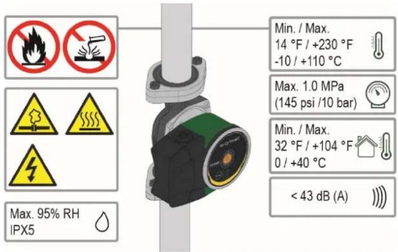
Figure 1: Pumped liquids, warnings and operating conditions
The circulators in the EVOSTA2, EVOSTA2d series represent a complete range of circulators.
These installation and operating instructions describe EVOSTA2, EVOSTA2d models. The type of model is indicated on the pack and on the identification plate.
The table below shows the EVOSTA2, EVOSTA2d models with built-in functions and features.
| Functions/features EVOSTA 2 EVO$TA 2d | ||
| Proportional pressure ● ● | ||
| Constant pressure ● ● | ||
| Constant curve ● ● | ||
| Dry-running protection ● | ||
| Automatic degassing | ● | |
Table 1: Functions
4. PUMPED LIQUIDS
Clean, free from solids and mineral oils, not viscous, chemically neutral, close to the properties of water (max. glycol contents 30%).
5. APPLICATIONS
EVOSTA2, EVOSTA2d series circulators allow integrated adjustment of the differential pressure which enables the circulator performance to be adapted to the actual requirements of the system. This determines considerable energy saving, a greater possibility of control of the system, and reduced noise.
EVOSTA2, EVOSTA2d circulators are designed for the circulation of:
– water in heating and conditioning systems.
– water in industrial water circuits.
– domestic water only for the versions with stainless steel pump body.
EVOSTA2, EVOSTA2d circulators are self-protected against:
- Overloads
– Lack of phase
– Excess temperature - Over-voltage and under-voltage
6. TECHNICAL DATA
| Supply voltage | 110-127V (+/-10%), 60 Hz |
| Absorbed power See electrical data plate | |
| Maximum current See electrical data plate | |
| Grade of protection IPX5 | |
| Protection class F | |
| TF Class TF 110 | |
| Motor protector No external motor protector is needed | |
| Maximum environment temperature 104 °F / 40°C | |
| Liquid temperature 14 °F ÷ 230 °F / -10 °C ÷ 110 °C | |
| Flow rate See Table3 | |
| Head | See |
| Maximum working pressure 1.0 Mpa | - 145 psi / 10 bar |
| Minimum working pressure | 0.1 Mpa - 14.5 psi / 1 bar |
| Lpa [dB(A)] | ≤ 43 |
Table 2: Technical data
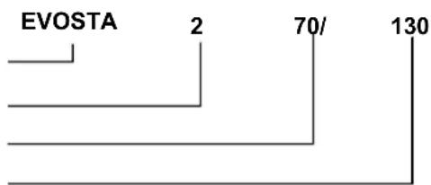
Designation index
(example)
Series name
2 = without display
2d = with display
Maximum head (feet)
Centre distance (inches)
| EVOSTA2, EVOSTA2d | Hmax (ft / m) | Qmax (gpm / m^3/h ) |
| EVOSTA2 110-127V 60Hz | 18 / 5.5 | 16 / 3.6 |
| EVOSTA2d 110-127V 60Hz | 18 / 5.5 | 16 / 3.6 |
Table 3: Maximum head (Hmax) and maximum flow rate (Qmax) of EVOSTA2, EVOSTA2d circulators
7. MANAGEMENT
7.1 Storage
All the circulators must be stored in a dry covered place, with possibly constant air humidity, free from vibrations and dust. They are supplied in their original pack in which they must remain until the time of installation. If this is not the case, accurately close the suction and delivery mouth.
7.2 Transport
Avoid subjecting the products to needless impacts and collisions. To lift and transport the circulator use lifting devices with the aid of the pallet supplied with it (if contemplated).
7.3 Weight
The adhesive plate on the packaging indicates the total weight of the circulator.
8. INSTALLATION

Always switch off the mains power supply before working on the electrical or mechanical part of the system. Wait for the warning lights on the control panel to go out before opening the appliance. The capacitor of the direct current intermediate circuit remains charged with dangerously high voltage even after the mains power has been turned off.
Only firmly cabled mains connections are admissible. The appliance must be earthed (IEC 536 class 1, NEC and other applicable standards).

Ensure that the voltage and frequency on the data plate of the EVOSTA2, EVOSTA2d circulator are the same as those of the power mains.
8.1 Mechanical installation
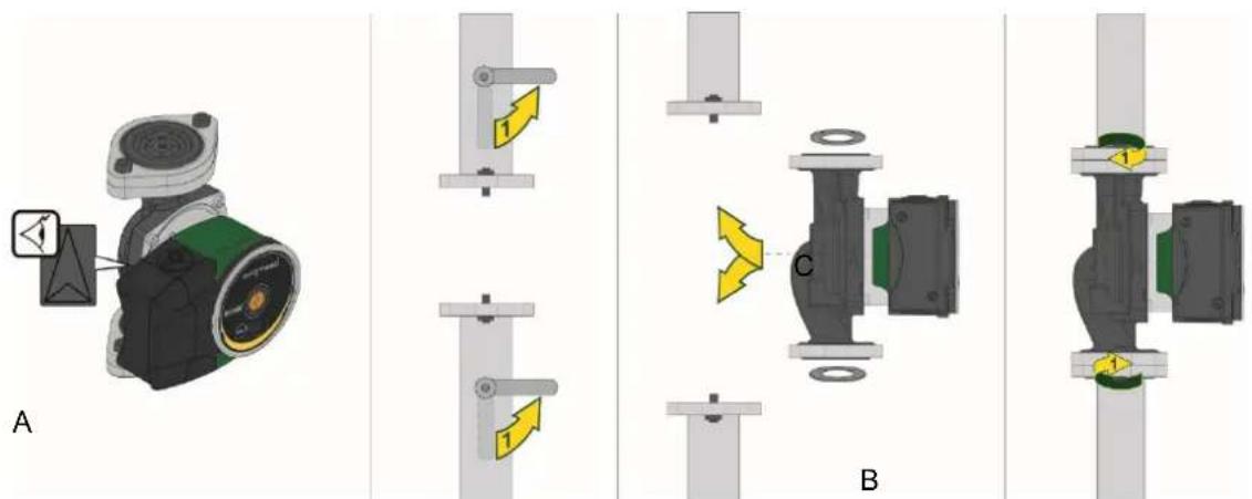
Figure 2: Mounting EVOSTA2, EVOSTA2d
The arrows on the pump housing indicate the flow direction through the pump. See fig. 1, pos. A.
- Fit the two gaskets when you mount the pump in the pipe. See fig. 1, pos. B.
- Install the pump with a horizontal motor shaft. See fig. 1, pos. C.
- Tighten the fittings.
8.2 User Interface Position

Always install the EVOSTA2, EVOSTA2d circulator with the motor shaft in a horizontal position.
Install the electronic control device in a vertical position.
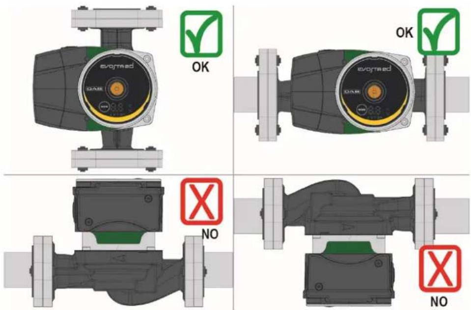
Figure 3: Assembly position
- The circulator may be installed in heating and conditioning systems on either the delivery pipe or the return pipe; the arrow marked on the pump body indicates the direction of flow.
- Install the circulator as far as possible above the minimum boiler level and as far as possible from bends, elbows and junction boxes.
- To facilitate control and maintenance operations, install an interception valve both on the suction pipe and on the delivery pipe.
Before installing the circulator, accurately flush the system with only water at 80^ . Then drain the system completely to eliminate any harmful substance that may have got into circulation. - Avoid mixing additives derived from hydrocarbons and aromatic products with the circulating water. It is recommended that the addition of antifreeze, where necessary, should not exceed 30% .
- In the event of heat insulation use the special kit (if provided) and ensure that the condensate draining holes in the motor casing are not closed or partly blocked.
- In the case of maintenance, always use a set of new gaskets.

Never insulate the electronic control device.
8.2.1 Positioning of the user interface in heating and domestic hot water systems
It is possible to position the user interface with the cable facing to the left, to the right, or downwards.
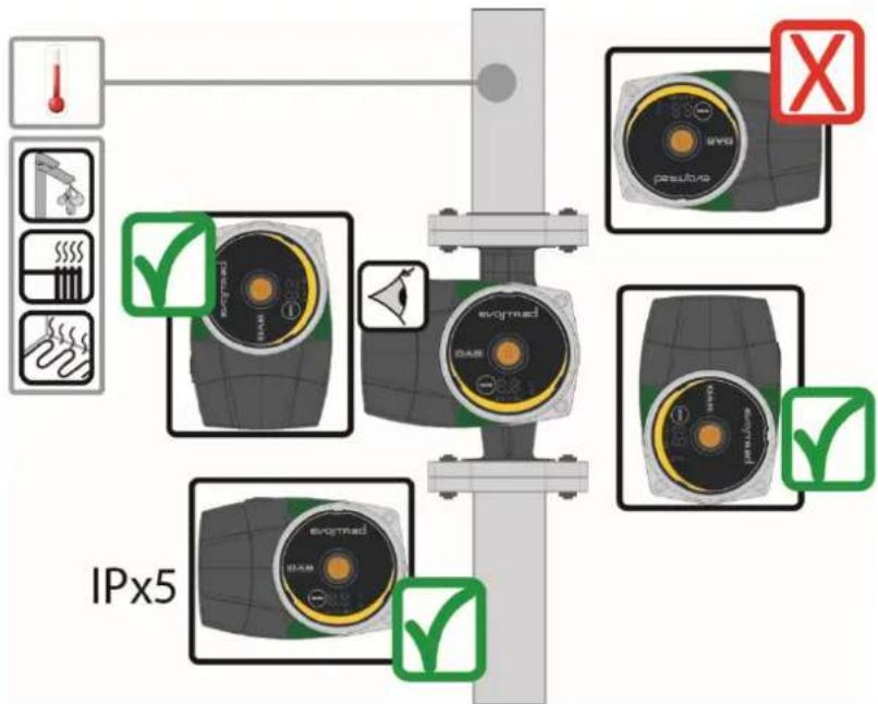
Figure 4: Positions of the user interface
8.2.2 Positioning of the user interface in conditioning and cold water systems The user interface can be positioned only with the cable facing downwards.
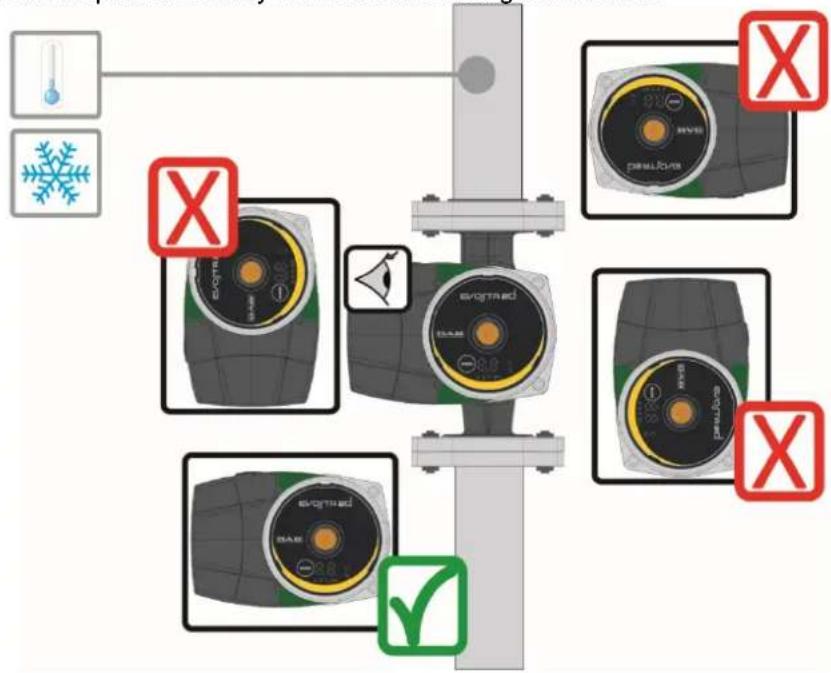
Figure 5: Positions of the user interface
8.3 Rotation of the user interface
If the circulator is installed on pipes in a horizontal position, it will be necessary to rotate the interface with the respective electronic device through 90 degrees in order to maintain the grade of IP protection and to allow the user a more convenient interaction with the graphic interface.
ENGLISH

Before rotating the circulator, ensure that it has been completely drained.
To rotate the EVOSTA2, EVOSTA2d circulator, proceed as follows:
- Remove the 4 fixing screws of the circulator head.
- Rotate the motor casing with the electronic control device through 90 degrees clockwise or counterclockwise, as necessary.
- Reassemble and tighten the 4 screws that fix the circulator head.

The electronic control device must always remain in vertical position!
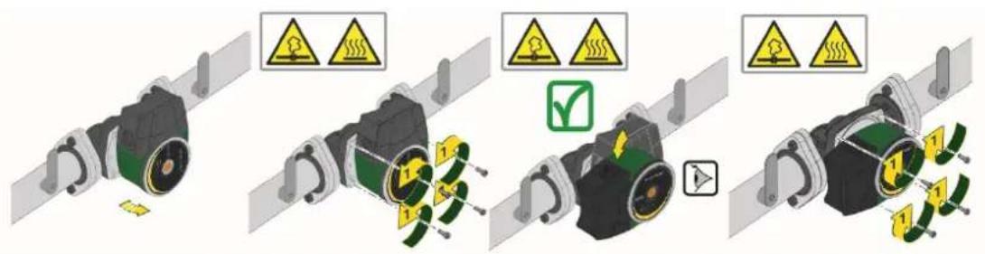
Figure 6: Changing the position of the user interface

ATTENTION
Water at high temperature. High temperature.

ATTENTION
System under pressure
- Before dismantling the pump, empty the system or close the interception valves on both sides of the pump. The pumped liquid may be at a very high temperature and high pressure.
8.4 Non-return valve
If the system is equipped with a non-return valve, ensure that the minimum pressure of the circulator is always higher than the valve closing pressure.
9. ELECTRICAL CONNECTIONS
The electrical connections must be made by expert, qualified personnel.

ATTENTION! ALWAYS RESPECT THE LOCAL SAFETY REGULATIONS.

Always switch off the mains power supply before working on the electrical or mechanical part of the system. Wait for the warning lights on the control panel to go out before opening the appliance. The capacitor of the direct current intermediate circuit remains charged with dangerously high voltage even after the mains power has been turned off.
Only firmly cabled mains connections are admissible. The appliance must be earthed (IEC 536 class 1, NEC and other applicable standards).

THE SYSTEM MUST BE CORRECTLY AND SAFELY EARTHED!

It is advised to install a correctly dimensioned differential switch to protect the system, type: class A with adjustable leakage current, selective.
The automatic differential switch must be marked with the following symbols:
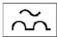
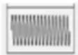
– The circulator does not require any external motor protection.
- Ensure that the supply voltage and frequency are the same as the values indicated on the electrical data plate of the circulator.
9.1 Power supply connection
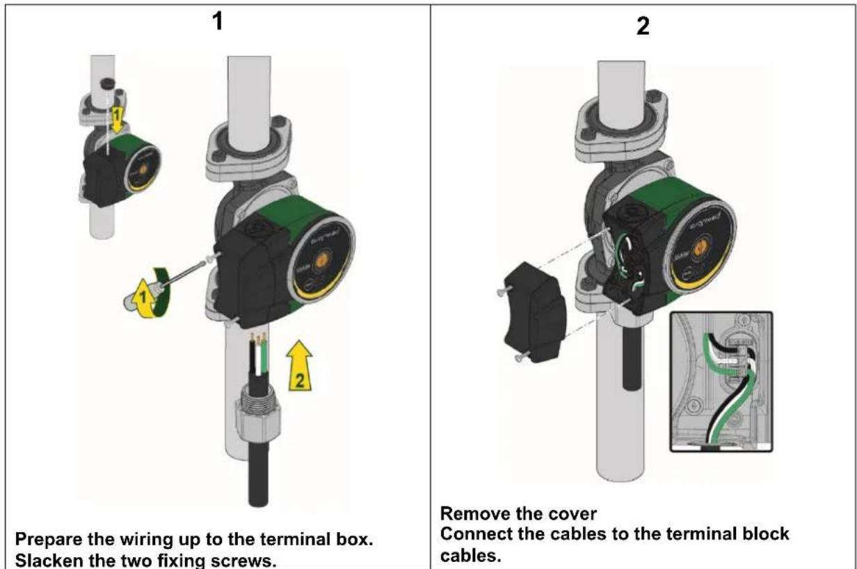
Tabella 4: Wiring Evosta2, EVOSTA2d
10. START

All the starting operations must be performed with the cover of the EVOSTA2, EVOSTA2d control panel closed.
Start the system only when all the electrical and hydraulic connections have been completed.
Avoid running the circulator when there is no water in the system.

As well as being at a high temperature and pressure, the fluid in the system may also be in the form of steam. DANGER OF SCALDING!
It is dangerous to touch the circulator. DANGER OF SCALDING!
Once all the electrical and hydraulic connections have been made, fill the system with water and if necessary with glycol (for the maximum glycol percentage see par. 4) and feed the system.
Once the system has been started it is possible to modify the operating modes to adapt better to the plant requirements.
10.1 Degassing the pump
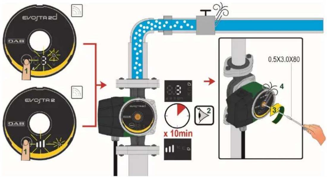
Figure 7: Venting of the pump

Always vent the pump before starting!
The pump must never run when dry.
10.2 Automatic Degassing
Automatic degassing occurs only for the Evosta2d pump. Hold down the Mode key for 3 sec and the function starts: 1 minute at maximum speed, then it passes to the set mode.

Figure 8: Automatic venting of the pump
11. FUNCTIONS
11.1 Regulating Modes
EVOSTA2, EVOSTA2d circulators allow the following regulating modes depending on plant requirements:
– Proportional differential pressure regulation depending on the flow present in the plant.
- Constant differential pressure regulation.
- Regulation with constant curve.
The regulating mode may be set through the EVOSTA2, EVOSTA2d control panel.
11.1.1 Regulation with Proportional Differential Pressure
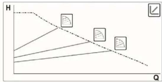
line
| H | Q | | ---- | ---- | | 1.0 | 0.0 | | 0.5 | 0.2 | | 0.0 | 0.4 | | -0.5 | 0.6 | | -1.0 | 0.8 | | -1.5 | 1.0 | | -2.0 | 1.2 | | -2.5 | 1.4 | | -3.0 | 1.6 | | -3.5 | 1.8 | | -4.0 | 2.0 | | -4.5 | 2.2 | | -5.0 | 2.4 | | -5.5 | 2.6 | | -6.0 | 2.8 | | -6.5 | 3.0 | | -7.0 | 3.2 | | -7.5 | 3.4 | | -8.0 | 3.6 | | -8.5 | 3.8 | | -9.0 | 4.0 | | -9.5 | 4.2 | | -10.0| 4.4 | | -10.5| 4.6 | | -11.0| 4.8 | | -11.5| 5.0 | | -12.0| 5.2 | | -12.5| 5.4 | | -13.0| 5.6 | | -13.5| 5.8 | | -14.0| 6.0 | | -14.5| 6.2 | | -15.0| 6.4 | | -15.5| 6.6 | | -16.0| 6.8 | | -16.5| 7.0 | | -17.0| 7.2 | | -17.5| 7.4 | | -18.0| 7.6 | | -18.5| 7.8 | | -19.0| 8.0 | | -19.5| 8.2 | | -20.0| 8.4 | | -20.5| 8.6 | | -21.0| 8.8 | | -21.5| 9.0 | | -22.0| 9.2 | | -22.5| 9.4 | | -23.0| 9.6 | | -23.5| 9.8 | | -24.0| 10.0 |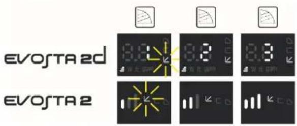
In this regulating mode the differential pressure is reduced or increased as the demand for water decreases or increases.
The Hs set point may be set from the display.
Regulation indicated for:
- Heating and conditioning plants with high load losses
- Plants with secondary differential pressure regulator
– Primary circuits with high load losses
– Domestic water recirculating systems with thermostatic valves on the rising columns
11.1.2 Regulation with Constant Differential Pressure
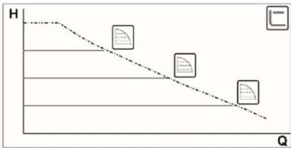
line
| Point | Value | |-------|-------| | 1 | High | | 2 | Medium| | 3 | Low |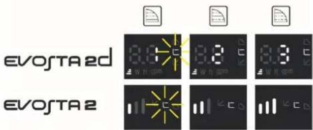
In this regulating mode the differential pressure is kept constant, irrespective of the demand for water, The Hs set point may be set from the display.
Regulation indicated for:
- Heating and conditioning plants with low load losses
- Single-pipe systems with thermostatic valves
- Plants with natural circulation
– Primary circuits with low load losses
– Domestic water recirculating systems with thermostatic valves on the rising columns
11.1.3 Regulation with constant curve
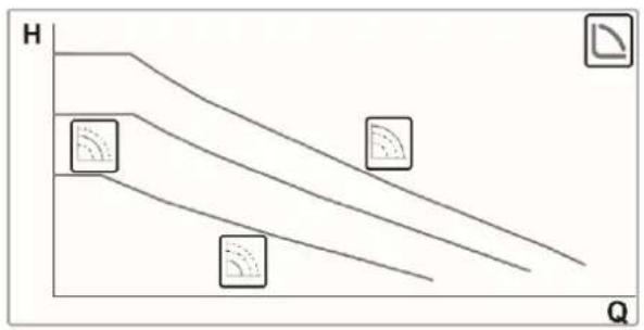
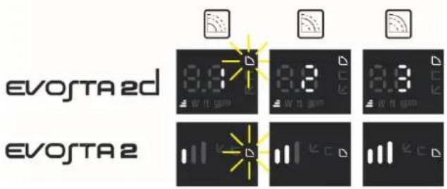
In this regulating mode the circulator works on characteristic curves at a constant speed.
Regulation indicated for heating and conditioning plants with constant flow.
12. CONTROL PANEL
The functions of EVOSTA2, EVOSTA2d circulators can be modified by means of the control panel on the cover of the electronic control device.
12.1 Elements on the Display
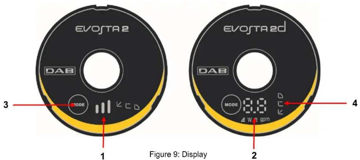
1 Luminous segments indicating the type of set curve
2 Display showing the instantaneous power absorption in Watt, the flow rate in m ^3 /h, the head in metres and the set curve.
3 Key for selecting the pump setting
4 Luminous segments indicating the set curve
12.2 Graphic Display
12.2.1 Luminous segments indicating the pump setting

The pump presents nine setting options that can be selected with the 'key'. The pump settings are indicated by six luminous segments on the display.
12.2.2 Key for selecting the pump setting
Whenever the key is pressed, the pump setting is changed. A cycle consists of pressing the key ten times.
12.2.3 Display Operation
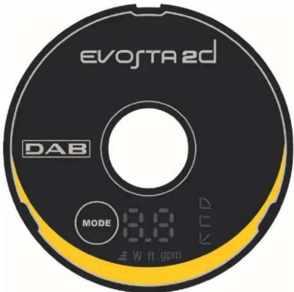
Figura 10: EVOSTA2d Display
The Evosta3 circulator has a display that is able to show the following values.

Height of the selected curve (1-2-3)
Instantaneous power absorption in Watt
Instantaneous head in feet
Instantaneous flow rate in gallon/minut
The values are shown in sequence for 3sec. Once the viewing cycle is ended, the display switches off and only the operating mode LED remains lit.
If the selection key is pressed within 10sec, the display performs 6 viewing cycles, then goes into stand-by.
If the key is pressed again within 10sec, the display performs 11 more viewing cycles to allow a greater reading time.
12.2.4 Settings of the pump operating mode
| EVOSTA2d | EVOSTA2 | ||
| 1 | 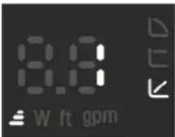 | 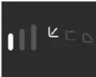 | Lower curve with proportional pressure, PP1 |
| 2 | 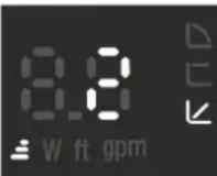 | 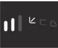 | Intermediate curve with proportional pressure, PP2 |
| 3 | 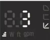 |  | Higher curve with proportional pressure, PP3 |
| 4 | 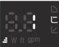 | 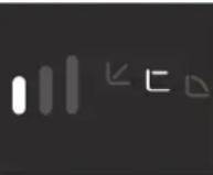 | Lower curve with constant pressure, CP1 |
| 5 | 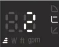 | 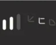 | Intermediate curve with constant pressure, CP2 |
| 6 | 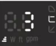 |  | Higher curve with constant pressure, CP3 |
| 7 | 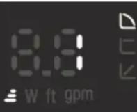 | 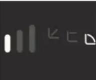 | Lower constant curve, I |
| 8 | 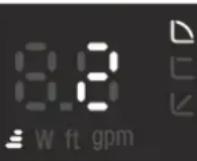 | 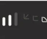 | Intermediate constant curve, II |
| 9 | 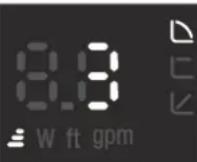 | 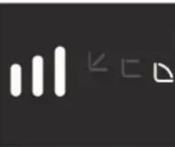 | Higher constant curve, III |
Table 5: Pump operating modes
13. FACTORY SETTINGS
Regulating mode: Minimum proportional differential pressure regulation
14. TYPES OF ALARM
| Alarm Description | |
| No. of curve height blinks | EVOSTA2 |
| 2 Blinks | TRIP: loss of motor control, may be caused by incorrect parameters, blocked rotor, disconnected phase, disconnected motor |
| 3 Blinks SHORT CIRCUIT: short circuit on phases or between phase and earth | |
| 4 Blinks OVERRUN: software fault | t |
| 5 Blinks | SAFETY: safety module error, may be caused by a sudden overcurrent or other hardware faults of the board |
| Alarm Code EVOSTA2d | |
| E1 | DRY RUN |
| E2 | TRIP: loss of motor control, may be caused by incorrect parameters, blocked rotor, disconnected phase, disconnected motor |
| E3 SHORT CIRCUIT: short circuit on phases or between phase and earth | |
| E4 OVERRUN: software fault | t |
| E5 | SAFETY: safety module error, may be caused by a sudden overcurrent or other hardware faults of the board |
Table 6: Types of Alarm
15. MAINTENANCE

Cleaning and maintenance activities must not be carried out by children (under 8 years of age) without supervision by a qualified adult. Before starting any work on the system, before starting to look for faults it is necessary to disconnect the power supply to the pump (take the plug out of the socket) and read the use and maintenance instructions.
16. DISPOSAL

This product or its parts must be disposed of in an environment-friendly manner and in compliance with the local regulations concerning the environment; use public or private local waste collection systems.
INDEX
- LÉGENDE 18
- GÉNÉRALITÉS....18
line
| Q | H | | --- | --- | | 0 | 1.0 | | 1 | 0.8 | | 2 | 0.6 | | 3 | 0.4 | | 4 | 0.2 | | 5 | 0.0 |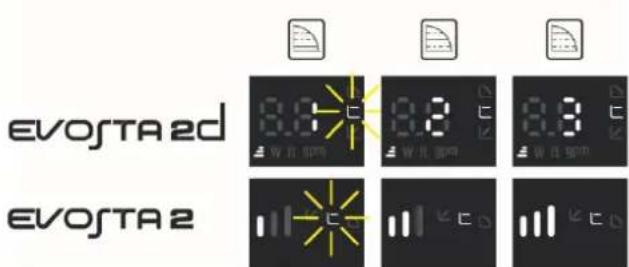
Image 10: Afficheur Evosta2d
line
| Q | H | | --- | --- | | 0 | 1.0 | | 1 | 0.8 | | 2 | 0.6 | | 3 | 0.4 | | 4 | 0.2 | | 5 | 0.0 |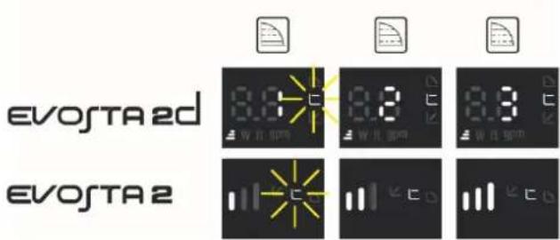
Figura 10: Pantalla Evosta2d
17. DIMENSIONS – DIMENSIONS - DIMENSIONES
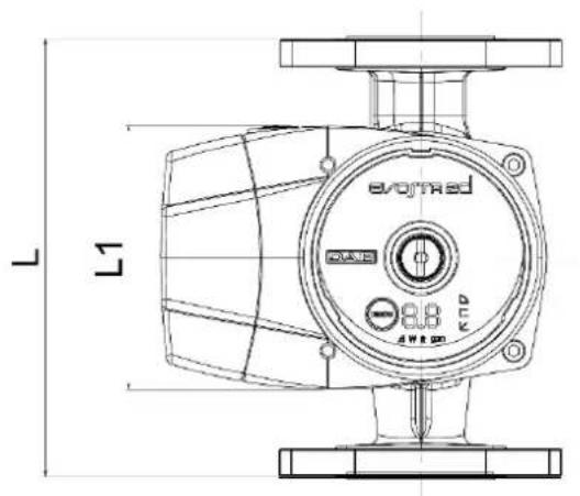
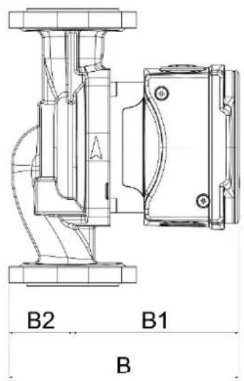
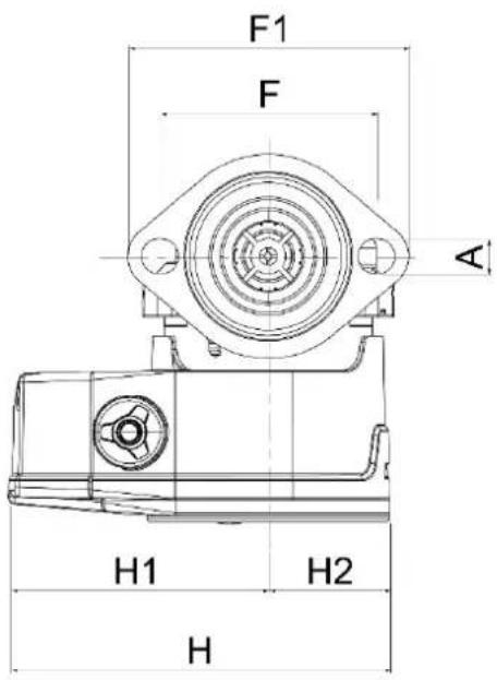
| Mod. | L L1 B | B1 B2 | H | |||||||||
| inch | mm | inch | mm | inch | mm | inch | mm | inch | mm | inch | mm | |
| EVOSTA2 55 110-127V 60Hz | 6-3/8 | 162 | 3-7/8 | 98 | 5-3/8 | 137 | 3-7/8 | 99 | 1-1/2 | 38 | 5-5/8 | 14 |
| EVOSTA2D 55 110-127V 60Hz | ||||||||||||
| EVOSTA2 55 SAN 110-127V 60Hz | ||||||||||||
| H1 H2 A | F F1 | 105 | ||||||||||
| inch | mm | inch | mm | inch | mm | inch | mm | inch | mm | |||
| 3-13/16 | 97 | 1-13/16 | 46 | 1/2 | 13 | 3-3/16 | 81 | 4-1/8 | ||||
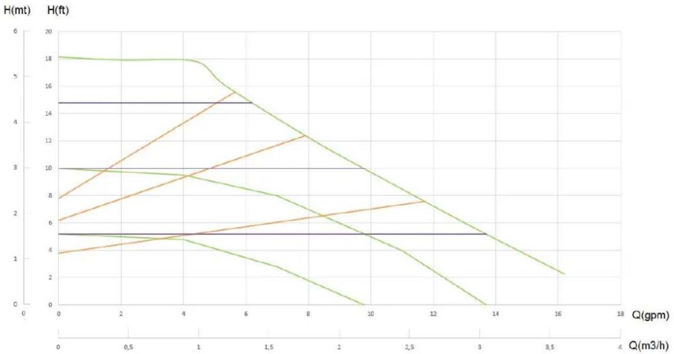
18. PERFORMANCE CURVES PERFORMANCES COURBES CURVAS PRESTACIONES
line
| Q(gpm) | H(mt) - Line 1 | H(mt) - Line 2 | H(mt) - Line 3 | H(mt) - Line 4 | H(mt) - Line 5 | H(mt) - Line 6 | H(mt) - Line 7 | |--------|----------------|----------------|----------------|----------------|----------------|----------------|----------------| | 0 | 18 | 8 | 6 | 5 | 4 | 3 | 2 | | 2 | 18 | 10 | 8 | 5 | 5 | 4 | 3 | | 4 | 18 | 12 | 10 | 5 | 6 | 5 | 4 | | 6 | 15 | 14 | 12 | 5 | 7 | 6 | 5 | | 8 | 12 | 16 | 14 | 5 | 8 | 7 | 6 | | 10 | 9 | 18 | 16 | 5 | 9 | 8 | 7 | | 12 | 6 | 20 | 18 | 5 | 10 | 9 | 8 | | 14 | 3 | 22 | 20 | 5 | 11 | 10 | 9 | | 16 | 0 | 24 | 22 | 5 | 12 | 11 | 10 | | 18 | - | 26 | 24 | 5 | 13 | 12 | 11 |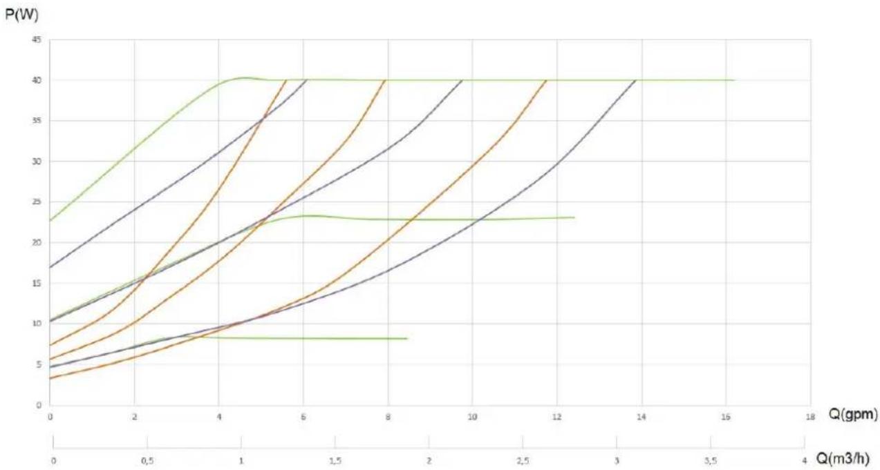
line
| Q(gpm) | P(W) - Line 1 | P(W) - Line 2 | P(W) - Line 3 | P(W) - Line 4 | P(W) - Line 5 | P(W) - Line 6 | P(W) - Line 7 | |--------|---------------|---------------|---------------|---------------|---------------|---------------|---------------| | 0 | 10 | 17 | 10 | 7 | 5 | 3 | 23 | | 2 | 15 | 22 | 15 | 10 | 7 | 6 | 30 | | 4 | 20 | 28 | 20 | 15 | 10 | 9 | 38 | | 6 | 25 | 32 | 25 | 20 | 13 | 12 | 40 | | 8 | 30 | 35 | 30 | 25 | 16 | 15 | 40 | | 10 | 35 | 38 | 35 | 30 | 20 | 18 | 40 | | 12 | 40 | 40 | 40 | 35 | 25 | 22 | 40 | | 14 | 40 | 40 | 40 | 40 | 30 | 25 | 40 | | 16 | 40 | 40 | 40 | 40 | 35 | 28 | 40 | | 18 | 40 | 40 | 40 | 40 | 40 | 30 | 40 |DAB PUMPS LTD.
6 Gilbert Court
Newcomen Way
Severalls Business Park
Colchester
Essex
C04 9WN - UK
salesuk@dwtgroup.com
Tel. +44 0333 777 5010
DAB PUMPS BV
'tHofveld 6 C1
info.belgium@dwtgroup.com
Tel. +32 2 4668353
DAB PUMPS INC.
3226 Benchmark Drive
Ladson, SC 29456 - USA
info.usa@dwtgroup.com
Tel. 1-843-797-5002
Fax 1-843-797-3366
000 DAB PUMPS
Novgorodskaya str. 1, block G
office 308, 127247, Moscow - Russia
info.russia@dwtgroup.com
Tel. +7 495 122 0035
Fax +7 495 122 0036
DAB PUMPS POLAND SP. z.o.o.
No.40 Kaituo Road, Qingdao Economic &
Technological Development Zone
Qingdao City, Shandong Province - China
PC: 266500
sales.cn@dwtgroup.com
Tel. +86 400 186 8280
Fax +86 53286812210
DAB PUMPS IBERICA S.L.
Calle Verano 18-20-22
28850 - Torrejón de Ardoz - Madrid
Spain
Info.spain@dwtgroup.com
Tel. +34 91 6569545
Fax: + 34 91 6569676
DAB PUMPS B.V.
Twenty One industrial Estate,
16 Purlin Street, Unit B, Warehouse 4
Olifantsfontein - 1666 - South Africa
info.sa@dwtgroup.com
Tel. +27 12 361 3997
info.germany@dwtgroup.com
Tel. +49 2151 82136-0
Fax +49 2151 82136-36
DAB PUMPS HUNGARY KFT.
H-8800
Nagykanizsa, Buda Ernő u.5
Hungary
Tel. +36 93501700
426 South Gippsland Hwy,
Dandenong South VIC 3175 – Australia
info.oceania@dwtgroup.com
Tel. +61 1300 373 677

WATER•TECHNOLOGY
DAB PUMPS S.p.A.
Via M. Polo, 14 - 35035 Mestrino (PD) - Italy
Tel. +39 049 5125000 - Fax +39 049 5125950
www.dabpumps.com


- INDEX OF FIGURES
- INDEX OF TABLES
- KEY
- GENERAL
- Read this documentation carefully before installation.
- Ensure that the product has not suffered any damage during transport or storage. Check that the outer casing is unbroken and in excellent conditions.
- Safety
- Responsibility
- Particular warnings
- PRODUCT DESCRIPTION
- PUMPED LIQUIDS
- APPLICATIONS
- TECHNICAL DATA
- Designation index
- MANAGEMENT
- Storage
- Transport
- Weight
- INSTALLATION
- Mechanical installation
- User Interface Position
- Positioning of the user interface in heating and domestic hot water systems
- Positioning of the user interface in conditioning and cold water systems The user interface can be positioned only with the cable facing downwards.
- Rotation of the user interface
- ENGLISH
- Before rotating the circulator, ensure that it has been completely drained.
- The electronic control device must always remain in vertical position!
- ATTENTION
- Non-return valve
- ELECTRICAL CONNECTIONS
- ATTENTION! ALWAYS RESPECT THE LOCAL SAFETY REGULATIONS.
- THE SYSTEM MUST BE CORRECTLY AND SAFELY EARTHED!
- Power supply connection
- START
- Degassing the pump
- Automatic Degassing
- FUNCTIONS
- Regulating Modes
- Regulation with Proportional Differential Pressure
- Regulation with Constant Differential Pressure
- Regulation with constant curve
- CONTROL PANEL
- Elements on the Display
- Graphic Display
- Luminous segments indicating the pump setting
- Key for selecting the pump setting
- Display Operation
- Settings of the pump operating mode
- FACTORY SETTINGS
- TYPES OF ALARM
- MAINTENANCE
- DISPOSAL
- INDEX
- DIMENSIONS – DIMENSIONS - DIMENSIONES
- PERFORMANCE CURVES PERFORMANCES COURBES CURVAS PRESTACIONES
- DAB PUMPS LTD.
- DAB PUMPS BV
- DAB PUMPS INC.
- DAB PUMPS
- DAB PUMPS POLAND SP. z.o.o.
- DAB PUMPS IBERICA S.L.
- DAB PUMPS B.V.
- DAB PUMPS HUNGARY KFT.
- DAB PUMPS S.p.A.
Brand : DAB
Model : EVOSTA2
Category : Pump