
ZV850SPSS - Basket Monogram - Free user manual and instructions
Find the device manual for free ZV850SPSS Monogram in PDF.

| Product Type | Range Hood |
| Brand | Monogram |
| Model | ZV850SPSS |
| Width | 30 in (76.2 cm) – model ZV850 |
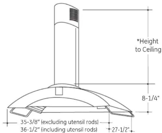
| Height (without utensil bars) | 35-3/8 in (89.9 cm) |
| Height (with utensil bars) | 36-1/2 in (92.7 cm) |
| Depth | 27-1/2 in (69.9 cm) |
| Weight (approx.) | Approximately 20 kg (45 lb) |
| Power supply | 120 V, 60 Hz, 15 or 20 A |
| Duct diameter | 6 in (15.24 cm), rigid metal |
| Installation type | External exhaust or recirculation |
| Installation height | 24 to 30 in above the cooking surface |
| Main material | Stainless steel |
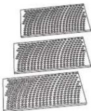
| Number of grease filters | 3, dishwasher safe |
| Charcoal filters (optional) | Included for recirculation mode |
| Lighting | Integrated, type not specified |
| Included accessories | Telescopic duct covers, side utensil bars, air deflector |
| Compatibility | Monogram electric or gas cooktops 30 in or 36 in |
| Safety guidelines | Do not use with a speed control; grounding mandatory |
| Service and parts | Call 1.800.444.1845 (service) or 1.800.626.2002 (parts) |
Frequently Asked Questions - ZV850SPSS Monogram
User questions about ZV850SPSS Monogram
0 question about this device. Answer the ones you know or ask your own.
Ask a new question about this device
Download the instructions for your Basket in PDF format for free! Find your manual ZV850SPSS - Monogram and take your electronic device back in hand. On this page are published all the documents necessary for the use of your device. ZV850SPSS by Monogram.
USER MANUAL ZV850SPSS Monogram
Installation Instructions
Island Vent Hood
ZV850, ZV855
Hotte Aspirante Îlot
READ AND SAVE THESE INSTRUCTIONS
BEFORE YOU BEGIN
Read these instructions completely and carefully.
- IMPORTANT – Save these instructions for local inspector's use.
- IMPORTANT – Observe all governing codes and ordinances.
- Note to Installer — Be sure to leave these instructions with the Consumer.
- Note to Consumer — Keep these instructions with your Owner's Manual for future reference.
- Skill Level — Installation of this appliance requires basic mechanical and electrical skills.
• Completion Time – 1 to 3 Hours. - Proper installation is the responsibility of the installer. Product failure due to improper installation is not covered under the warranty.
For Monogram local service in your area, call 1.800.444.1845. For Monogram service in Canada, call 1.800.561.3344. For Monogram Parts and Accessories, call 1.800.626.2002.
CAUTION:
Due to the weight and size of these vent hoods and to reduce the risk of personal injury or damage to the product, TWO PEOPLE ARE REQUIRED FOR PROPER INSTALLATION.
WARNING:
To reduce the risk of fire or electrical shock, do not use this range hood with any external solid-state speed control device. Any such alteration from original factory wiring could result in damage to the unit and/or create an electrical safety hazard.
TO REDUCE THE RISK OF FIRE, USE ONLY METAL DUCTWORK.
WARNING: TO REDUCE THE RISK OF FIRE, ELECTRICAL SHOCK OR INJURY TO PERSONS, OBSERVE THE FOLLOWING:
A. Use this unit only in the manner intended by the manufacturer. If you have any questions, contact the manufacturer.
B. Before servicing or cleaning the unit, switch the power off at the service panel and lock the service disconnecting means to prevent the power from being switched on accidentally. When the service disconnecting means cannot be locked, securely fasten a prominent warning device, such as a tag, to the service panel.
CAUTION: FOR GENERAL VENTILATING USE ONLY. DO NOT USE TO EXHAUST HAZARDOUS MATERIALS, EXPLOSIVE MATERIALS OR VAPORS.
⚠ WARNING: TO REDUCE THE RISK OF FIRE, ELECTRICAL SHOCK OR INJURY TO PERSONS, OBSERVE THE FOLLOWING:
- Installation work and electrical wiring must be done by qualified person(s) in accordance with all applicable codes and standards, including fire-rated construction.
-
Sufficient air is needed for proper combustion and exhausting of gases through the flue (chimney) of fuel burning equipment to prevent back-drafting. Follow the heating equipment manufacturer's guidelines and safety standards, such as those published by the National Fire Protection Association (NFPA), the American Society for Heating, Refrigeration and Air Conditioning Engineers (ASHRAE) and the local code authorities. When applicable, install any makeup (replacement) air system in accordance with local building code requirements. Visit GEAppliances.com for available makeup air solutions.
-
When cutting or drilling into walls or ceilings, do not damage electrical wiring and other hidden utilities.
- Ducted systems must always be vented to the outdoors.
- Local codes vary. Installation of electrical connections and grounding must comply with applicable codes. In the absence of local codes, the vent should be installed in accordance with National Electrical Code ANSI/NFPA 70-1990 or latest edition.
CAUTION: To reduce risk of fire and to properly exhaust air, be sure to duct air outside—do not vent exhaust air into spaces within walls or ceilings or into attics, crawl spaces or garages.
Design Information
CONTENTS
Design Information
Models Available 3
Product Dimensions 3
Advance Planning
Ductwork Planning 4
Ceiling Framing for Adequate Support 4
Installation Preparation
Duct Fittings 5
Power Supply 6
Tools and Materials Required 6
Remove the Packaging 7
Check Installation Hardware 7
Determine Installation Height 8
Install Ceiling Support Structure 9-11
Installation Instructions
Installation – Vented to the Outside 12–16
Step 1, Mount Template ....12
Step 2, Install Upper Support Frame ....12
Step 3, Install Lower Support Frame ....12
Step 4, Secure Wiring ....13
Step 5, Size and Install Ductwork ....13
Step 6, Install Decorative Duct Covers ....14
Step 7, Install Hood ....15
Step 8, Connect Electrical 15
Step 9, Slide Duct Cover
Down, Install Side Utensil Rods 15
Step 10, Install Filters....16
Step 11, Finalize Installation....16
Installation Instructions
Installation - Recirculating 17-21
Step 1, Mount Template .....17
Step 2, Install Upper Support Frame ....17
Step 3, Install Lower Support Frame ....18
Step 4, Secure Wiring ....18
Step 5, Size and Install Ductwork ....18
Step 6, Install Decorative Duct Covers ....19
Step 7, Install Hood ....20
Step 8, Connect Electrical ....20
Step 9, Slide Duct Cover
Down, Install Side Utensil Rods 20
Step 10, Install Filters....21
Step 11, Finalize Installation....21
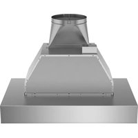
MODELS AVAILABLE
Model ZV850
Model ZV855
These hoods may be installed to vent to the outdoors, or they may be installed for recirculating operation.
All necessary parts for recirculating operation are supplied with the hood. No kits required.
• These vent hoods can be installed over any 30' or 36"
Monogram electric or gas cooktop except Monogram Professional cooktops or ranges larger than 30".
- Reversible duct covers accommodate recirculating operation.
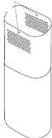
- The telescopic duct covers conceal the ductwork running from the top of the hood to the ceiling.
- The supplied duct cover is sized to reach ceiling heights over 8 feet. See the table on page 8.
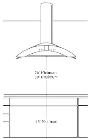
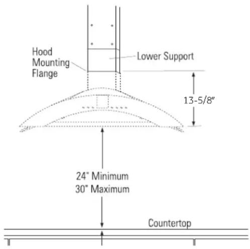
PRODUCT DIMENSIONS AND CLEARANCES
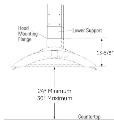
The vent hood must be installed 24" minimum and 30" maximum above the cooking surface.
NOTE: Installation height should be measured from the cooking surface to the lowest part of the hood.
ZX8510SPSS Duct Cover Accessory
This accessory is available for installation with ceiling heights of 8' 7" to over 10 feet. See the table on page 8.
The duct cover accessory must be on-site with the hood at the time of installation.
DUCTWORK PLANNING
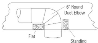
- The hood is designed to be vented vertically through the ceiling. Use locally supplied elbows to vent horizontally through the rear wall.
- Determine the exact location of the vent hood.
- Plan the route for venting exhaust to the outdoors.
- Use the shortest and straightest duct route possible. For satisfactory performance, duct run should not exceed 100' equivalent length for any duct configurations.
- Refer to "Duct Fittings" chart to compute the maximum permissible length for duct runs to the outdoors.
- Use rigid metal ductwork only.
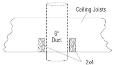
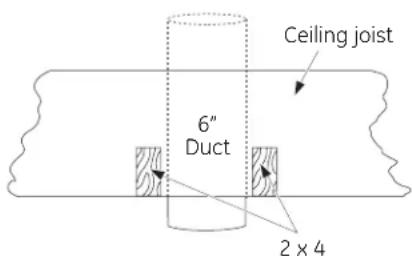
Through The Ceiling

Vent Between Ceiling Joists
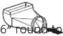
- This vent hood must use 6" round duct. The 6" round duct can transition to 3-1/4" x 10" or 3-1/4" x 12".
• Install the house duct to run horizontally between ceiling joists or straight up through the roof. - Install a wall or roof cap with damper at the exterior opening. Order the wall or roof cap and any transition and length of duct needed in advance.
- When applicable, install any makeup (replacement) air system in accordance with local building code requirements. Visit GEAppliances.com for available makeup air solutions.
A WARNING: TO REDUCE THE RISK OF FIRE, USE ONLY RIGID METAL DUCTWORK.
CEILING FRAMING FOR ADEQUATE SUPPORT
- These vent hoods are heavy. Adequate structural support must be provided. The ceiling structure must be capable of supporting the weight of the hood and any inadvertent user contact loads (approximately 200 pounds). The hood support frame will be supported by 2 × 4 minimum cross-framing.
- Installation will be easier if the vent hood is installed before the cooktop or countertop below is installed.
Accessory Duct Cover
A duct cover accessory may be required for your installation, depending on ceiling height.
DUCT FITTINGS
This Hood Must Use an 6" Round Duct. It Can Transition to 3-1/4" x 10" or 3-1/4" x 12" Duct.
Use this chart to compute maximum permissible lengths for duct runs to outdoors.
NOTE: Do not exceed maximum permissible equivalent lengths!
Maximum duct length: 100 foot for range hoods.
Flexible ducting:
If flexible metal ducting is used, all the equivalent feet values in the table should be doubled. The flexible metal duct should be straight and smooth and extended as much as possible.
DO NOT use flexible plastic ducting.
NOTE: Any home ventilation system, such as a ventilation hood, may interrupt the proper flow of combustion air and exhaust required by fireplaces, gas furnaces, gas water heaters and other naturally vented systems. To minimize the chance of interruption of such naturally vented systems, follow the heating equipment manufacturer's guidelines and safety standards such as those published by NFPA and ASHRAE. When applicable, install any makeup (replacement) air system in accordance with local building code requirements. Visit GEAppliances.com for available makeup air solutions.
| Duct Piece Dimensions Length* Used Length | Equivalent | Total Quantity | |||
Rc  | (per straight | foot | length) | ||
 | 3-1/4" × 10" straight | 1 ft. (per foot | length) | ||
9(  | 12 ft. | ||||
45°  | 7 ft. | ||||
 | 3-1/4" × 10" 3-1/4" × 12" 90° | elbow | 14 ft. 10 ft. | ||
 | 3-1/4" × 10" 3-1/4" × 12" 45° | elbow | 8 ft. 6 ft. | ||
 | 3-1/4" × 10" 3-1/4" × 12" | 33 ft. 24 ft. | |||
| 9( ow | |||||
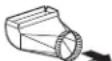
 | 6 rectangular | " round to | 2 ft. | ||
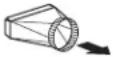 | Rectangular to 8" round | 2 ft. | |||
 | 3-1/4" × 10" 3-1/4" × 12" rectangular transition 90° elbow | 4 ft. 4 ft. | |||
 | 3-1/4" × 10" 3-1/4" × 12" Rectangular transition 90° elbow | 4 ft. 4 ft. to | 6" round | ||
| Rc [BWCH] | cap with | 24 ft. damper | |||
 | 3-1/4" × 10" 3-1/4" × 12" Rectangular with | 24 ft. 18 ft. wall damper | cap | ||
| Rouk (GRAY) | of cap | 33 ft. | |||
| * Actual length of straight duct plus duct fitting equivalent. Equivalent length of duct pieces are based on actual tests conducted by GE Evaluation Engineering and reflect requirements for good venting performance with any ventilation hood. | Total Duct Run____ | ||||
POWER SUPPLY
IMPORTANT – (Please read carefully)
WARNING:
FOR PERSONAL SAFETY, THIS APPLIANCE MUST BE PROPERLY GROUNDED.
Remove house fuse or open circuit breaker before beginning installation.
Do not use an extension cord or adapter plug with this appliance. Follow National Electrical Code or prevailing local codes and ordinances.
Electrical supply
This vent hood must be supplied with 120V, 60Hz, and connected to an individual, properly grounded branch circuit, and protected by a 15- or 20-amp circuit breaker or time-delay fuse.
- Wiring must be 2-wire with ground.
- If the electrical supply does not meet the above requirements, call a licensed electrician before proceeding.
- Route house wiring as close to the installation location as possible. Route additional length from ceiling joists to reach the junction box on the hood.
- Connect the wiring to the house wiring in accordance with local codes.
Grounding instructions
The grounding conductor must be connected to a ground metal, permanent wiring system, or an equipment-grounding terminal or lead on the hood.
WARNING: The improper connection of the equipment-grounding conductor can result in a risk of electric shock. Check with a qualified electrician or service representative if you are in doubt whether the appliance is properly grounded.
TOOLS AND MATERIALS REQUIRED
(NOT SUPPLIED)


Pencil and tape measure
Spirit level
Hammer
Phillips screwdriver

Utility knife
Flashlight

Metal snips
Electric drill with 5/32" bits, #2 Phillips and 7/16" socket
Pliers
natural_image
Line drawing of a wooden double staircase with no text or symbolsStepladder
Masking tape

Wire cutter/stripper

Saber saw or keyhole saw
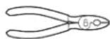
UL-listed wire nuts
Aluminized
duct tape
Strain relief for junction box
Plumb
6" round metal duct, length to suit installation
120V, 60Hz. 15- or 20-Amp, 2-wire with ground, properly grounded branch circuit
REMOVE THE PACKAGING

UTION:
Wear gloves to protect
against sharp edges.
The vent hood is packed with the duct cover and support frames.
- Remove the hood, parts and packaging.
- Remove junction box cover.
• Install strain relief onto junction box cover (not supplied).
NOTE: Additional tools, materials and hardware are required to construct your ceiling support.
Check Installation Hardware
Locate the hardware accessory bag packed with the hood and check contents.
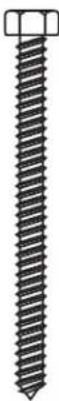
4 Hex-head wood lag screws (6 mm x 2-1/2" or 1/4 x 2-1/2")

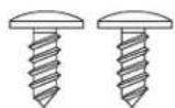
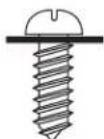
2 Phillips-head
duct cover
screws
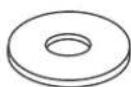
4 Flat washers
2 Stop screws (One is in the service manual envelope. Leave that screw in the envelope.)
8 Frame attachment screws with washers (attached to accessory support frames)
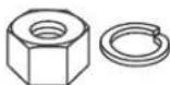
4 (10 mm) Nuts and lock washers
natural_image
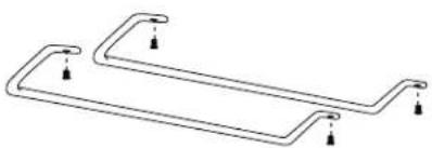
Pure electrical circuit lines without any symbols2 Utensil rods with 4 machine screws
natural_image
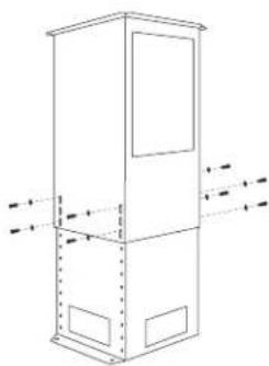
Technical line drawing of a vertical cabinet or enclosure with internal compartments and directional arrows indicating flow or movement (no text or symbols)Support frames with 8 screws and 8 washers
Mounting screw holes
Decorative
duct covers
Template
natural_image
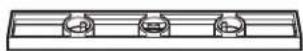
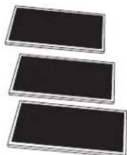
Three identical grid-patterned rectangular panels with no visible text or symbols3 Stainless steel grease filters
Additional Parts for Recirculating Operation

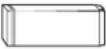
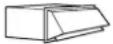
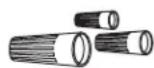
Air deflector with upper duct connector and 4 small flat-head screws
natural_image
Three rectangular dark rectangular panels with metallic borders, arranged horizontally (no text or symbols visible)3 Charcoal filters
DETERMINE INSTALLATION HEIGHT
- Telescopic duct covers are provided to conceal the ductwork running to the ceiling.
- This hood can be installed for vented or recirculating operation. All necessary parts are shipped with the hood.
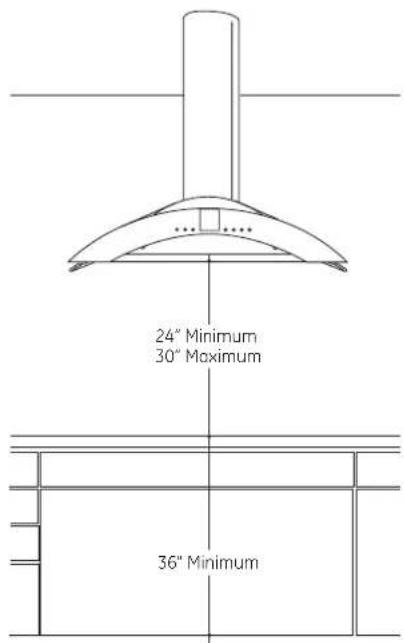
NOTE: Installation height should be measured from the cooking surface to the bottom of the hood.
The vent hood must be installed 24" min. and 30" max. above the cooking surface. The hood installation height, from the cooking surface to the bottom of the hood, depends upon ceiling height and duct cover limitations.
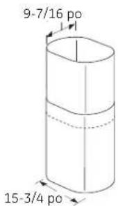
DUCT COVER DIMENSIONS

ZX8510SPSS Duct Cover Accessory
The accessory is available for installation with ceiling heights of 8' 7" to over 10 feet. This accessory consists of two 26-1/4" duct covers and one 31" upper support frame piece.
| Ceiling Height | ZV850/ZV855 Installation Heights | In Lower Frame 20.75"Frame 20.75" | Lower Duct 18"Upper Duct 18" | Upper Frame 31" + Supplied Lower Frame | Lower Duct 26.25"Upper Duct 26.25" | |
| *Possible VENTED Installation Height | RECIR | |||||
| 7' 11" | 24" | 24" | SUPPLIED FRAME | SUPPLIED DUCT COVERS | ||
| 8' | 24" to 25" | 24" to 25" | ||||
| 8' 1" | 24" to 26" | 24" to 26" | ||||
| 8' 2" | 25" to 27" | 24" to 27" | ||||
| 8' 3" | 26" to 28" | 24" to 28" | ||||
| 8' 4" | 27" to 29" | 24" to 29" | ||||
| 8' 5" | 28" to 30" | 24" to 30" | ||||
| 8' 6" | 29" to 30" | 25" to 30" | ||||
| 8' 7" | 30" | 26" to 30" | ||||
| 8' 8" | 27" to 30" | |||||
| 8' 9" | 28" to 30" | |||||
| 8' 10" | 29" to 30" | |||||
| 8' 11" | 30" | |||||
| 8' 7" | 24" | 24" | ZX8510SPSS - ACCESSORY UPPER FRAME | ZX8510SPSS - ACCESSORY DUCT COVERS | ||
| 8' 8" | 24" to 25" | 24" to 25" | ||||
| 8' 9" | 24" to 26" | 24" to 26" | ||||
| 8' 10" | 24" to 27" | 24" to 27" | ||||
| 8' 11" | 24" to 28" | 24" to 28" | ||||
| 9' | 24" to 29" | 24" to 29" | ||||
| 9' 1" | 24" to 30" | 24" to 30" | ||||
| 9' 2" | 24" to 30" | 24" to 30" | ||||
| 9' 3" | 24" to 30" | 24" to 30" | ||||
| 9' 4" | 24" to 30" | 24" to 30" | ||||
| 9' 5" | 24" to 30" | 24" to 30" | ||||
| 9' 6" | 24" to 30" | 24" to 30" | ||||
| 9' 7" | 24" to 30" | 24" to 30" | ||||
| 9' 8" | 25" to 30" | 24" to 30" | ||||
| 9' 9" | 26" to 30" | 24" to 30" | ||||
| 9' 10" | 27" to 30" | 24" to 30" | ||||
| 9' 11" | 28" to 30" | 25" to 30" | ||||
| 10' | 29" to 30" | 26" to 30" | ||||
| 10' 1" | 30" | 27" to 30" | ||||
| 10' 2" | 28" to 30" | |||||
| 10' 3" | 29" to 30" | |||||
| 10' 4" | 30" | |||||
*Based on 36" countertop height.
CONSTRUCT CEILING SUPPORT
Plan the Location of the Hood and Ductwork
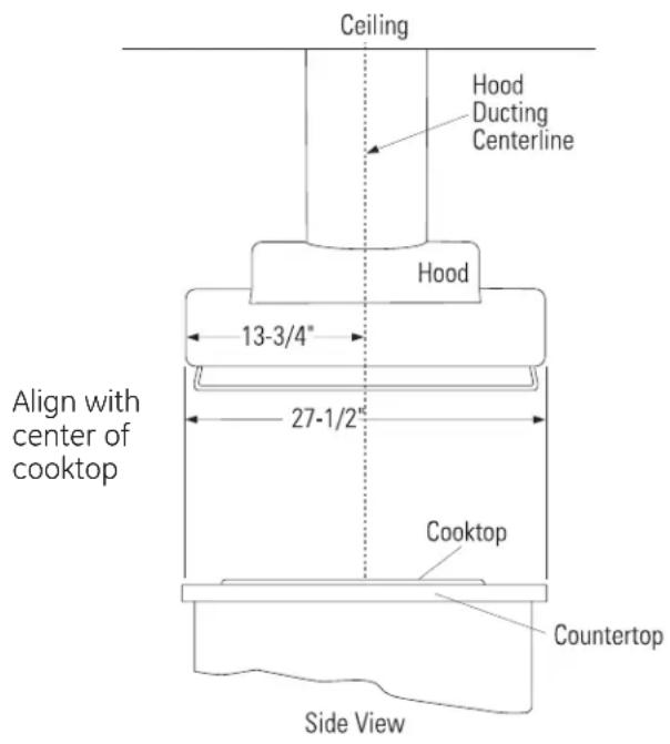
- Use a plumb bob to check the location. The countertop/cooktop below the hood must be centered with the hood.
- The hood should extend beyond the front and rear edge of the cooking appliance.
- The duct in the ceiling must be centered over the cooktop.
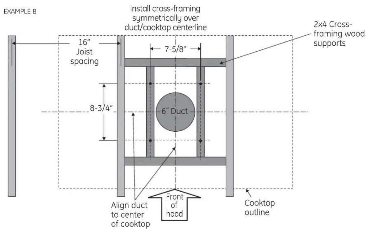
Ceiling Support Structure
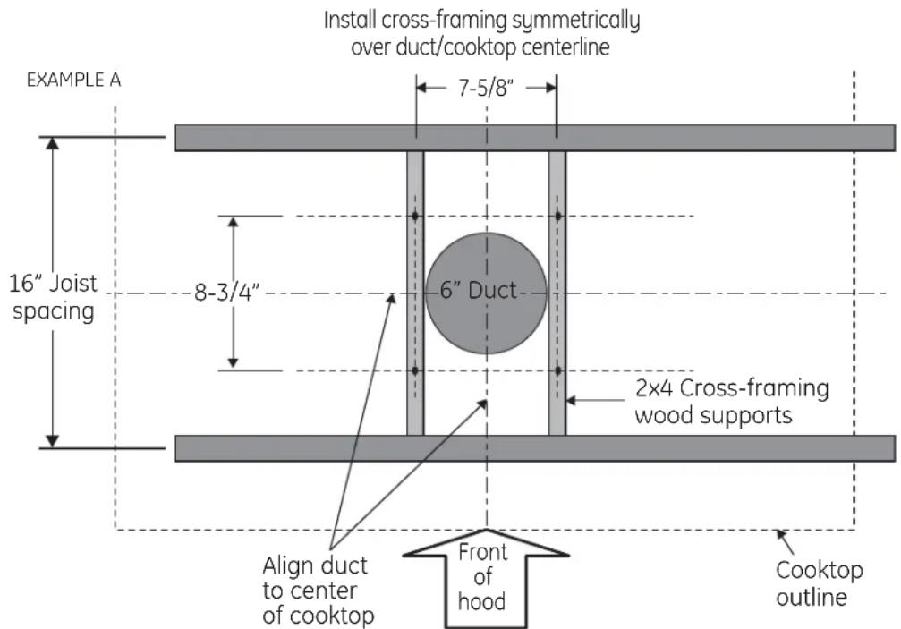
- At the hood location, install cross-framing between ceiling joists as shown. (2x4 wood supports are required to support the weight of the hood.)
- Arrange cross-framing in the ceiling to suit the existing structure.
- Your ceiling joists will be like one of the following examples.
Top view – ceiling joists parallel to front of hood
CONSTRUCT CEILING SUPPORT (Continued)
Top view – ceiling joists run perpendicular to front of hood
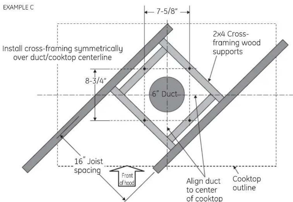
Top view – ceiling joists at angle to front of hood
CONSTRUCT CEILING SUPPORT (Continued)
- Secure each 2 × 4 block with at least four (4), #10 wood screws, 3" long (not supplied). Use 8 wood screws total for the two supports.
- The cross framing must be accurately aligned to assure correct positioning of the hood.
- The cross framing must be level in all directions. Check with a spirit level and adjust if necessary.
IMPORTANT: The ceiling structure must be capable of supporting the weight of the hood (approximately 200 pounds) and any inadvertent user contact loads. The hood support frame will be supported by the 2 x 4 cross framing.
Ductwork for Installations Vented to the Outdoors
- Use the shortest and straightest duct route possible. For satisfactory performance, duct run should not exceed 100 feet equivalent length for any duct configuration.
- Refer to "Duct Fittings" chart to compute the maximum permissible length for duct runs to the outdoors.
- This vent hood must use 6" round rigid duct.
A WARNING: TO REDUCE THE RISK OF FIRE, USE ONLY RIGID METAL DUCTWORK.
- Install the house ductwork to run horizontally between ceiling joists or straight up through the roof.
Finish the Ceiling
- Finish the ceiling surface. Be sure to mark location of the ceiling joists and cross framing. Check to be sure the ceiling is level; use shims if necessary.
Vent straight up through the ceiling
INSTALLATION - VENTED TO THE OUTSIDE
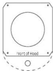
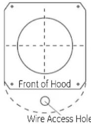
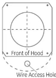
1 MOUNT TEMPLATE
- Align the template with the marks on the ceiling and tape in place.
- Be sure the template is oriented correctly, with the front of the hood.
- Use a plumb to be sure the mounting holes will provide parallel alignment with the countertop below.
• Center punch all hole locations. - Drill pilot holes in the 4 screw locations. Use a 5/32" bit and drill approximately 1-1/2" deep.
- Cut wire access hole approximately 1" dia.
- Cut the 6-1/2" duct opening through the ceiling.
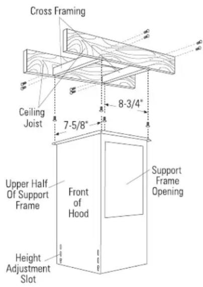
2 INSTALL UPPER SUPPORT FRAME
- Secure the upper support frame to the ceiling joists and/or cross framing with the 4 screws provided. For maximum rigidity and strength, the screws must be driven into the center of the joists and/or cross-framing.
- Check to be sure the support frame is level, vertically and horizontally.
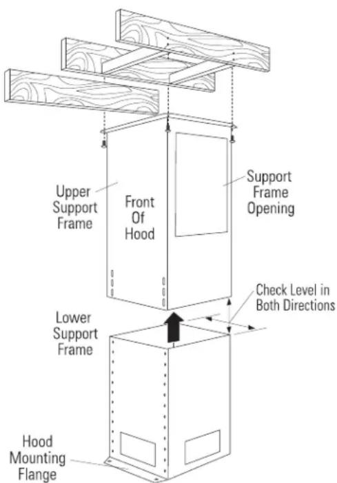
3 INSTALL LOWER SUPPORT FRAME
- Insert lower support frame into the upper support frame and loosely secure with 8 screws and washers (4 on the front and 4 on the back sides).
- Adjust the lower support frame up or down to the desired height above the countertop. Tighten screws.
natural_image
Pure geometric lines forming a rectangle with no text, numbers, or symbolsIMPORTANT: Again, check to be sure the support is level in both directions. There is no way to level the hood after the hood is secured to the frame.
INSTALLATION - VENTED TO THE OUTSIDE
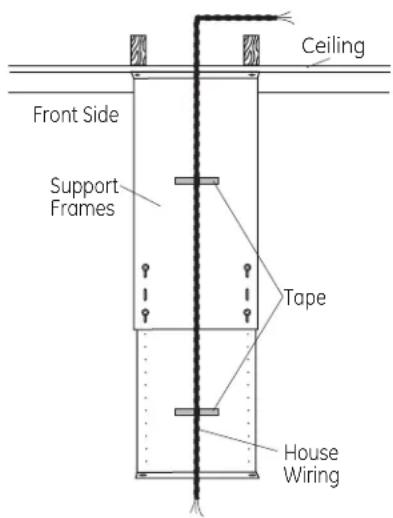
4 SECURE WIRING
- Route house wiring through the ceiling hole and pull a length to reach the hood junction box.
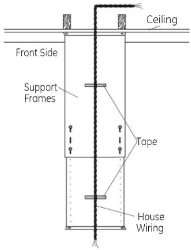
- Tape the wire to the front of the frame support to prevent damage during installation and service.
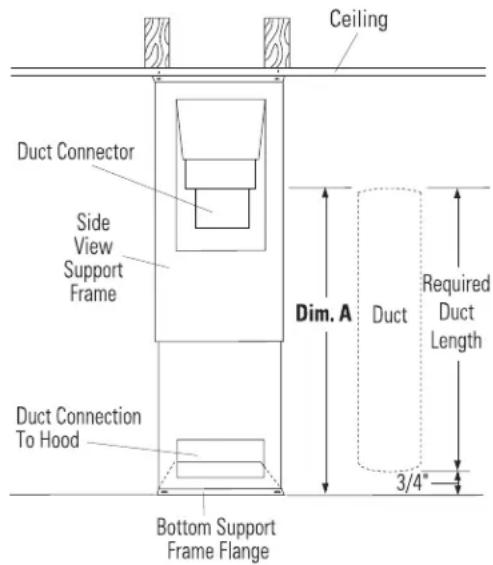
5 SIZE AND INSTALL DUCTWORK
- Measure from house duct (Dim. A) to bottom of support frame.
- Add at least 1" for duct overlap at the top.
- Subtract 3/4" for hood insertion into the bottom of the frame.
- Cut the 6" dia. duct to the required length.
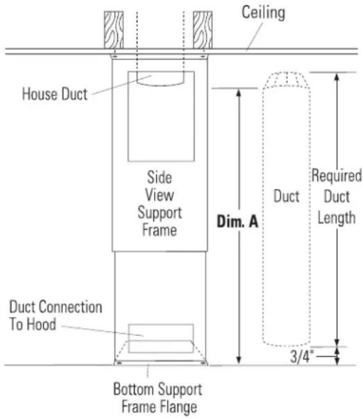
NOTE: The bottom end of the duct must be flared slightly, to facilitate installation of the hood.
- Install duct up through support frames onto the house duct. Push duct up until it is 3/4" from the bottom of the support frame flange.
- Secure the duct to house duct connection with screws and seal with duct tape.
- Seal duct connection with duct tape, making sure connection is secured in place.
INSTALLATION - VENTED TO THE OUTSIDE
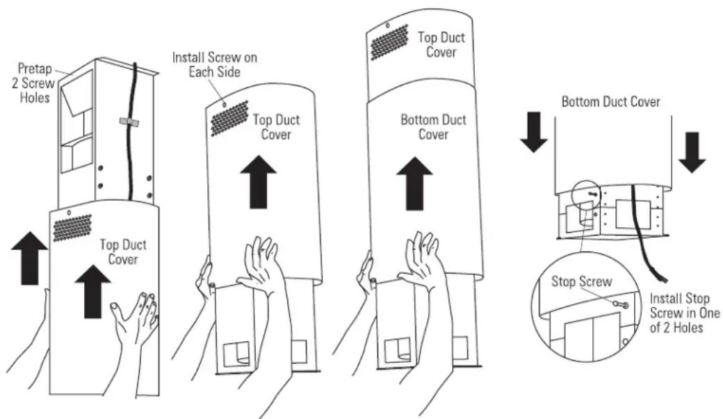
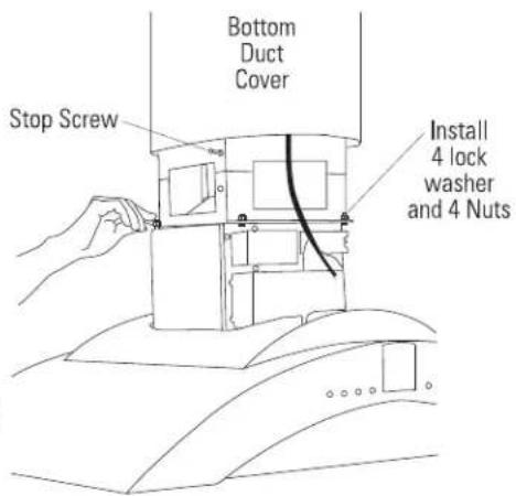
6 INSTALL DECORATIVE DUCT COVERS
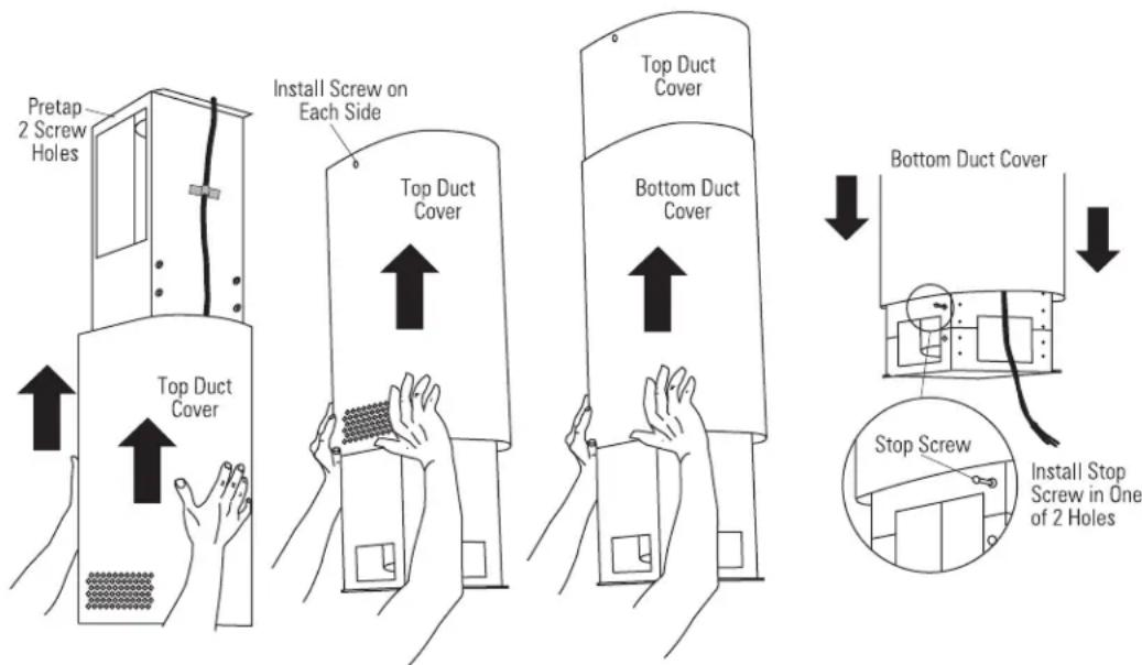
- Pretap or drive decorative screw into the screw holes on the support frame. This will make screw installation easier.
- Separate the two decorative duct covers.
- Select the inside or top cover with the vent hole pattern on one end.
For this vented installation to the outside, the hole pattern should be located at the bottom.
- Locate the 2 supplied duct cover screws.
- Slide the decorative duct cover over the support frame and push to the ceiling.
- Attach the inside duct cover to the hood support at the top with 2 supplied duct cover screws.
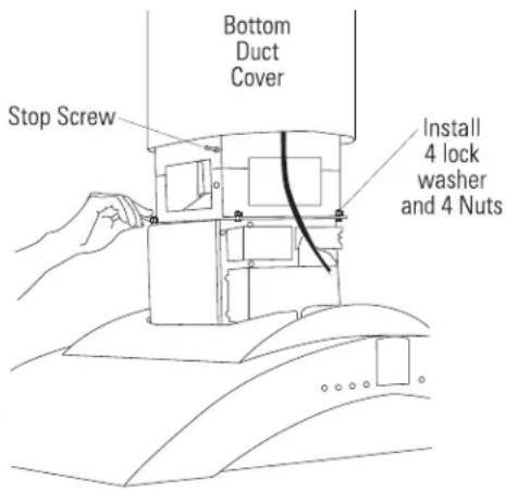
-
Locate the stop screw in the hardware bag
-
Install the stop screw into one of the two holes and tighten against the frame to allow the second duct cover to slide up and pass over.
- Slide the lower duct cover over the installed upper duct cover and push up past the stop screw location.
- Back out the stop screw far enough to support the bottom duct cover and prevent it from sliding down onto the top of the hood.
A CAUTION: The stop screw must be installed. Failure to do so could result in personal injury or damage to the duct cover.
INSTALLATION - VENTED TO THE OUTSIDE
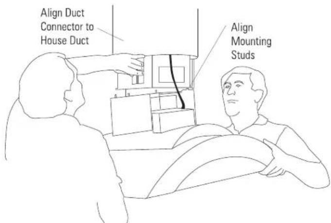
7 INSTALL HOOD
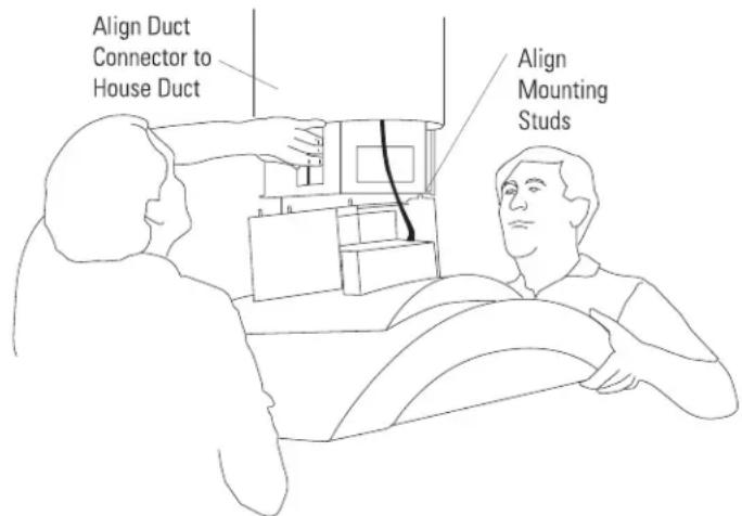
NOTE: TWO PEOPLE ARE REQUIRED TO COMPLETE THIS INSTALLATION!
- Lift the hood up to the support frame. Carefully align the hood mounting studs into the support frame holes, and at the same time, guide the hood duct connector into the duct.
-
Install 4 nuts and lock washers. Tighten with a 10 mm wrench.
-
Check hood level in both directions.
- Seal the duct connection with duct tape.
NOTE: Do not drive screws through this duct connection. Doing so will prevent proper damper operation.
8 CONNECT ELECTRICAL
Verify that power is turned off at the source.
A WARNING: If house wiring is not 2-wire with a ground wire, a ground must be provided by the installer. When house wiring is aluminum, be sure to use U.L.-approved antioxidant compound and aluminum-to-copper connectors.
- Install strain relief onto the knockout of the junction box cover.
- Insert house wiring through strain relief and tighten.
- Connect white leads to branch circuit white lead.
- Connect black leads to branch circuit black lead.
- Connect green/yellow leads to branch circuit green or bare ground lead.
- Secure all connections with wire nuts on each electrical connector.
- Push wires into junction box and replace cover. Be sure wires are not pinched.
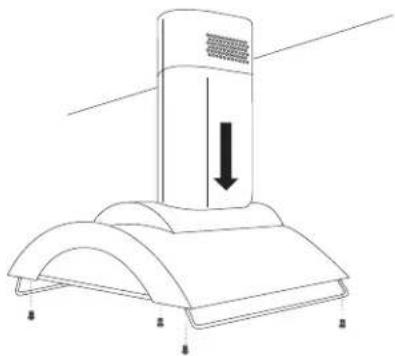
9 SLIDE DUCT COVER DOWN, INSTALL SIDE UTENSIL RODS
- Slide the lower duct cover up and above the stop screw.
- Drive the stop screw in close to the frame.
- Slide the lower duct cover down against the top of the hood. The duct cover should be seated into the pocket on top of the hood.
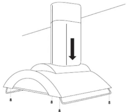
natural_image
Technical line drawing of a mechanical component with a downward arrow indicating force or motion (no text or symbols)• Install the side utensil rods with screws as shown.
INSTALLATION - VENTED TO THE OUTSIDE
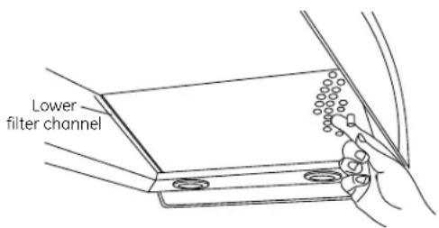
10 INSTALL FILTERS
- Remove protective film on filters.
- Tip the filter into the lower channel at the rear of the opening. Push back, lift and pull the knob forward until the filter rests on the channel.
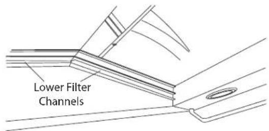
• Install all three metal grease filters.
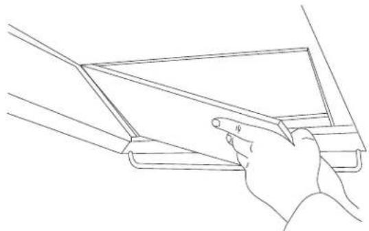
natural_image
Line drawing of a hand holding a rectangular object with a diagonal line, no text or symbols present- Turn power on. If the filter light on the control panel glows, adjust the right-side filter in the channel to engage the switch arm.
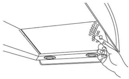
natural_image
Line drawing of a hand inserting a component into a metal bracket (no text or symbols)11 FINALIZE INSTALLATION
- Remove the protective film covering the control panel on the front face of the hood and any other packaging materials.
- Make sure the filters are seated properly when installed and the filter light is not on.
- Be sure fan and lights operate correctly. Refer to the Owner's Manual for operating instructions and the Problem Solver.
INSTALLATION - RECIRCULATING
1 MOUNT TEMPLATE
- Align the template with the marks on the ceiling and tape in place.
- Be sure the template is oriented correctly, with the front of the hood.
- Use a plumb to be sure the mounting holes will provide parallel alignment with the countertop below.
• Center punch all hole locations.
- Drill pilot holes in the 4 screw locations. Use a 5/32" bit and drill approximately 1-1/2" deep.
- Cut wire access hole approximately 1" dia.
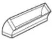
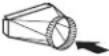
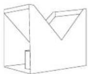
2 INSTALL AIR DEFLECTOR AND UPPER SUPPORT FRAME
The duct connector is shipped inside the deflector.
- Snap the plastic connector out of the deflector and remove. Turn it over. From the bottom, snap the connector over the opening.
- Slide the assembled deflector into the upper support frame and secure with 4 small screws.
- Secure the upper support frame to the ceiling joists and/or cross framing with the 4 screws provided. For maximum rigidity and strength, the screws must be driven into the center of the joists and/or cross framing.
- Check to be sure the support frame is level, vertically and horizontally.
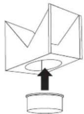
natural_image
Simple line drawing of a 3D geometric object with an arrow pointing upward to a cylindrical base (no text or symbols)
INSTALLATION - RECIRCULATING
3 INSTALL LOWER SUPPORT FRAME
- Insert lower support frame into the upper support frame and loosely secure with 8 screws and washers (4 on the front and 4 on the back sides).
- Adjust the lower support frame up or down to the desired height above the countertop. Tighten screws.
IMPORTANT: Again, check to be sure the support is level in both directions. There is no way to level the hood after the hood is secured to the frame.
4 SECURE WIRING
- Route house wiring through the ceiling hole and pull a length to reach the hood junction box.
- Tape the wire to the front of the frame support to prevent damage during installation and service.
5 SIZE AND INSTALL DUCTWORK
- Measure from top duct connector (Dim. A) to bottom of support frame.
- Subtract 3/4" for hood insertion into the bottom of the frame.
- Cut the 6" dia. duct to the required length.
NOTE: The bottom end of the duct must be flared slightly, to facilitate installation of the hood.
- Install duct up through support frames onto the duct connector. Push duct up until it is 3/4" from the bottom of the support frame flange. See illustration.
- Seal duct connection with duct tape, making sure the connection is secured in place.
INSTALLATION - RECIRCULATING
6 INSTALL DECORATIVE DUCT COVERS
- Pretap or drive decorative screw into the screw holes on the support frame. This will make screw installation easier.
- Separate the two decorative duct covers.
- Select the inside or top cover with the vent hole pattern on one end.
For this recirculating installation, the hole pattern should be located at the top.
- Locate the 2 supplied duct cover screws.
- Slide the decorative duct cover over the support frame and push to the ceiling.
- Attach the inside duct cover to the hood support at the top with 2 supplied duct cover screws.
-
Locate the stop screw in the hardware bag
-
Install the stop screw into one of the two holes and tighten against the frame to allow the second duct cover to slide up and pass over.
- Slide the lower duct cover over the installed upper duct cover and push up past the stop screw location.
- Back out the stop screw far enough to support the bottom duct cover and prevent it from sliding down onto the top of the hood.
CAUTION: The stop screw must be installed. Failure to do so could result in personal injury or damage to the duct cover.
INSTALLATION - RECIRCULATING
7 INSTALL HOOD
NOTE: Before installing the hood, the metal damper flaps on top of the hood exhaust outlet may be removed. Do not remove the duct transition. The damper is not required for this recirculating operation.
NOTE: TWO PEOPLE ARE REQUIRED TO COMPLETE THIS INSTALLATION!
- Lift the hood up to the support frame. Carefully align the hood mounting studs into the support frame holes, and at the same time, guide the hood duct connector into the duct.
• Install 4 nuts and lock washers. Tighten with a 10 mm wrench.
- Check hood level in both directions.
- Seal the duct connection with duct tape.
NOTE: Do not drive screws through this duct connection. Doing so will prevent proper damper operation (if present).
8 CONNECT ELECTRICAL
Verify that power is turned off at the source.
WARNING: If house wiring is not 2-wire with a ground wire, a ground must be provided by the installer. When house wiring is aluminum, be sure to use U.L.-approved antioxidant compound and aluminum-to-copper connectors.
• Install strain relief onto the knockout of the junction box cover.
- Insert house wiring through strain relief and tighten.
- Connect white leads to branch circuit white lead.
- Connect black leads to branch circuit black lead.
- Connect green/yellow leads to branch circuit green or bare ground lead.
- Secure all connections with wire nuts on each electrical connector.
- Push wires into junction box and replace cover. Be sure wires are not pinched.
9 SLIDE DUCT COVER DOWN, INSTALL SIDE UTENSIL RODS
- Slide the lower duct cover up and above the stop screw.
- Drive the stop screw in close to the frame.
- Slide the lower duct cover down against the top of the hood. The duct cover should be seated into the pocket on top of the hood.
natural_image
Technical line drawing of a mechanical component with a downward arrow indicating force or motion (no text or symbols)• Install the side utensil rods with screws as shown.
INSTALLATION - RECIRCULATING
10 INSTALL FILTERS
- There are two channels inside the back and front of the hood. These channels will hold the charcoal filters and stainless steel grease filters in place.
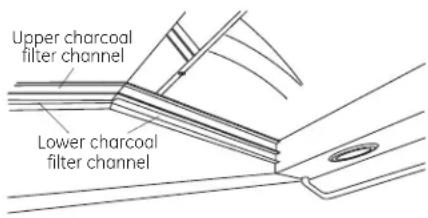
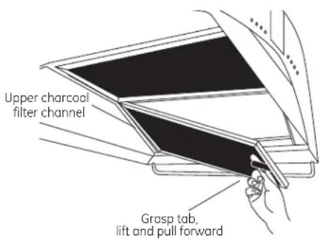
Install charcoal filters
- Remove protective film on the charcoal filters.
- Tip charcoal filters into the upper (top) channels at the rear of the opening. Grasp the filter tab, lift and pull forward until it rests in the front upper channel.
• Install all 3 charcoal filters.
Install grease filters
- Remove protective film from grease filters.
- Tip the grease filter into the lower channel at the rear of the opening. Push back, lift and pull the knob forward until the filter rests on the channel.
• Install all 3 grease filters. - Turn power on. If the filter light on the control panel glows, adjust the right-side filter in the channel to engage the switch arm.
11 FINALIZE INSTALLATION
- Remove protective film covering the control panel on the front face of the hood and any remaining packaging materials.
- Make sure the filters are seated properly when installed and the filter light is not on.
- Be sure fan and lights operate correctly. Refer to the Owner's Manual for operating instructions and the Problem Solver.
LISEZ ET CONSERVEZ CES INSTRUCTIONS
AVANT DE COMMENCER
Installation - Recyclage 37-41
Etape 1, Montage du gabarit ....37
natural_image
Line drawing of a wooden double staircase with no text or symbolsEscabeau
Ruban-cache
Pinces
natural_image
Pure electrical circuit lines without any symbolsnatural_image
Technical line drawing of a cabinet or enclosure with internal compartments and directional arrows indicating flow or movement (no text or symbols)Gabarit

natural_image
Three identical grid-patterned rectangular panels with no visible text or symbolsnatural_image
Three rectangular dark rectangular panels with metallic borders, arranged horizontally (no text or symbols visible)3 filtres à charbon
DÉTERMINATION DE LA HAUTEUR D'INSTALLATION
DIMENSIONS DU CACHE CONDUIT
natural_image
Technical line drawing of a mechanical component with a downward arrow indicating force or direction (no text or symbols)natural_image
Line drawing of a hand holding a rectangular object with a diagonal line, no text or symbols presentnatural_image
Line drawing of a hand holding a tray with a grid of dots, no text or symbols present11 FINALISATION DE L'INSTALLATION
natural_image
Simple line drawing of a 3D geometric structure with an upward arrow emerging from it, no text or symbols present.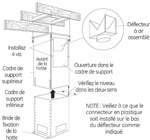
natural_image
Technical line drawing of a mechanical component with a downward arrow indicating motion (no text or symbols)natural_image
Line drawing of a four-tiered ladder structure (no text or symbols)Escalera
Cinta
adhesiva
Alicates
Sierra sable o serrucho de calar
Alicate pelacables
natural_image
Pure diagram of two curved pipe or conduit with tassels, no text or symbols presentnatural_image
Technical line drawing of a vertical cabinet or enclosure with internal compartments and directional arrows indicating flow or movement (no text or symbols)natural_image
Three identical rectangular panels with uniform grid patterns, no text or symbols visible3 filtros de grasa de acero inoxidable
natural_image
Three identical rectangular panels with dark and light edges, no text or symbols visible.3 filtros de carbón
natural_image
Technical line drawing of a mechanical component with a downward arrow indicating force or motion (no text or symbols)natural_image
Line drawing of a hand holding a rectangular object with a ruler, no text or symbols presentnatural_image
Line drawing of a hand inserting a component into a metal bracket (no text or symbols)natural_image
Simple line drawing of a 3D geometric object with an arrow pointing upward to a cylindrical base (no text or symbols)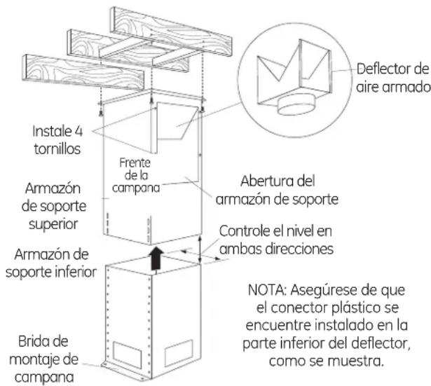
natural_image
Simple line drawing of a mechanical component with a downward arrow indicating force or direction (no text or symbols)NOTE: While performing installations described in this book, safety glasses or goggles should be worn.
For Monogram® local service in your area, call 1.800.444.1845.
NOTE: Product improvement is a continuing endeavor at General Electric. Therefore, materials, appearance and specifications are subject to change without notice.
General Electric Company
Louisville, KY 40225
GEAppliances.com

- Installation Instructions
- READ AND SAVE THESE INSTRUCTIONS
- BEFORE YOU BEGIN
- CAUTION:
- WARNING:
- WARNING: TO REDUCE THE RISK OF FIRE, ELECTRICAL SHOCK OR INJURY TO PERSONS, OBSERVE THE FOLLOWING:
- CAUTION: FOR GENERAL VENTILATING USE ONLY. DO NOT USE TO EXHAUST HAZARDOUS MATERIALS, EXPLOSIVE MATERIALS OR VAPORS.
- ⚠ WARNING: TO REDUCE THE RISK OF FIRE, ELECTRICAL SHOCK OR INJURY TO PERSONS, OBSERVE THE FOLLOWING:
- CAUTION: To reduce risk of fire and to properly exhaust air, be sure to duct air outside—do not vent exhaust air into spaces within walls or ceilings or into attics, crawl spaces or garages.
- Design Information
- CONTENTS
- Advance Planning
- Installation Preparation
- MODELS AVAILABLE
- PRODUCT DIMENSIONS AND CLEARANCES
- ZX8510SPSS Duct Cover Accessory
- DUCTWORK PLANNING
- CEILING FRAMING FOR ADEQUATE SUPPORT
- Accessory Duct Cover
- Flexible ducting:
- POWER SUPPLY
- Electrical supply
- Grounding instructions
- TOOLS AND MATERIALS REQUIRED
- REMOVE THE PACKAGING
- UTION:
- Check Installation Hardware
- Additional Parts for Recirculating Operation
- DETERMINE INSTALLATION HEIGHT
- CONSTRUCT CEILING SUPPORT
- Plan the Location of the Hood and Ductwork
- Ceiling Support Structure
- CONSTRUCT CEILING SUPPORT (Continued)
- Ductwork for Installations Vented to the Outdoors
- A WARNING: TO REDUCE THE RISK OF FIRE, USE ONLY RIGID METAL DUCTWORK.
- Finish the Ceiling
- INSTALLATION - VENTED TO THE OUTSIDE
- MOUNT TEMPLATE
- INSTALL UPPER SUPPORT FRAME
- INSTALL LOWER SUPPORT FRAME
- SECURE WIRING
- SIZE AND INSTALL DUCTWORK
- INSTALL DECORATIVE DUCT COVERS
- For this vented installation to the outside, the hole pattern should be located at the bottom.
- INSTALL HOOD
- NOTE: TWO PEOPLE ARE REQUIRED TO COMPLETE THIS INSTALLATION!
- CONNECT ELECTRICAL
- SLIDE DUCT COVER DOWN, INSTALL SIDE UTENSIL RODS
- INSTALL FILTERS
- FINALIZE INSTALLATION
- INSTALLATION - RECIRCULATING
- INSTALL AIR DEFLECTOR AND UPPER SUPPORT FRAME
- For this recirculating installation, the hole pattern should be located at the top.
- CAUTION: The stop screw must be installed. Failure to do so could result in personal injury or damage to the duct cover.
- Install charcoal filters
- Install grease filters
- LISEZ ET CONSERVEZ CES INSTRUCTIONS
- AVANT DE COMMENCER
- DÉTERMINATION DE LA HAUTEUR D'INSTALLATION
- FINALISATION DE L'INSTALLATION
Brand : Monogram
Model : ZV850SPSS
Category : Basket