
MIM-A60N - Air conditioner SAMSUNG - Free user manual and instructions
Find the device manual for free MIM-A60N SAMSUNG in PDF.

| Product Type | Thermostat Kit for Air Conditioner |
| Brand | Samsung |
| Model | MIM-A60N |
| Dimensions (L x H x D) | 128 x 130 x 38 mm |
| Weight | Approximately 200 g |
| Power Supply | 24 V AC (via external transformer) |
| Operating Temperature | 0 °C to 50 °C |
| Operating Humidity | 10 % to 85 % RH |
| Compatibility | Compatible Samsung indoor units |
| Thermostat Inputs | Y1, Y2 (cooling), W1, W2 (heating), G, G1, G2, G3 (ventilation) |
| Outputs to Indoor Unit | Y1, Y2, W1, W2, G, G1, G2, G3, R (24 V), C (common) |
| Transformer Input | TR (24 V), TC (common) |
| Digital Inputs | DI1 (emergency), DI2 (not used), COM |
| Digital Outputs | DO1 (error feedback), DO2 (external emergency heating) |
| External Sensor | NTC Thermistor (optional, MRW-TA) |
| Communication with Indoor Unit | F3, F4 |
| DIP Settings | 12 switches for priority, DI/DO, fan speed, etc. |
| Rotary Settings | RSW1 (cooling temperature), RSW2 (heating temperature) |
| LED Indicators | 5 LEDs (1 green, 1 red, 3 orange) for diagnostics |
| Reset Button | Yes (SW5) |
| Wall Mounting | Via 2 or more screws (provided) |
| Maintenance | Clean with a dry cloth; do not use liquids |
| Safety | Professional installation; cut off power before intervention |
| Repairability | Spare parts available via Samsung customer service |
Frequently Asked Questions - MIM-A60N SAMSUNG
User questions about MIM-A60N SAMSUNG
0 question about this device. Answer the ones you know or ask your own.
Ask a new question about this device
Download the instructions for your Air conditioner in PDF format for free! Find your manual MIM-A60N - SAMSUNG and take your electronic device back in hand. On this page are published all the documents necessary for the use of your device. MIM-A60N by SAMSUNG.
USER MANUAL MIM-A60N SAMSUNG
• Thank you for purchasing this Samsung Product.
- Before operating this unit, please read this installation manual carefully and retain it for future reference.

Contents
Safety Information 3
Checklist Prior to Installation 5
Accessories 5 External Dimensions 5 Product layout 6
Installing the Thermostat Kit 7
Thermostat Kit installation 7 Configuring operation options 9 Inspecting the Thermostat Kit 14 Resetting custom settings 15 Wiring Examples 16
Troubleshooting 19
2 English
Safety Information
This installation manual provides details on how to install the Thermostat Kit on the indoor unit of your Samsung System Air Conditioner.
Make sure you read this manual thoroughly to ensure the proper installation of the product. (When installing other accessories, refer to their respective manuals.)
| WARNING | Hazards or unsafe practices that may result in severe personal injury or death. |
| CAUTION | Hazards or unsafe practices that may result minor personal injury or property damage. |

WARNING
Before installing the product, contact the Service Center.
- Improper installation creates the risk of product malfunction, water leakage, electric shock or fire.
Safely install the product on a stable surface that can bear its weight.
- If the product is installed on a surface that is not stable, it may fall and become damaged.
When connecting to power, check the rated voltage.
- Incorrect power connection may damage the product or cause a fire.
Do NOT move or reinstall a product that has been installed.
• This creates the risk of electric shock or fire.
Do NOT arbitrarily repair or modify the product.
- This creates the risk of damage to the product, electric shock or fire. If the product requires repair, contact the Service Center.
Make sure the product has been installed properly according to this installation manual.
- If the product is not installed properly, there is a risk of electric shock or fire.
Wiring must be done by qualified personnel according to the instructions specified herein.
- If the product is not installed properly due to a failure to follow the instructions herein, there is a risk of product malfunction, electric shock or fire.
To dispose of the product, contact the Service Center.
Safety Information

CAUTION
Do NOT install the product in a location where flammable gas may leak.
• This creates the risk of fire or explosion.
Do NOT install the product in a location where oil or moisture may leak.
- If the product is used in a location where oil, moisture or sulfurous acid gas has leaked, the product may malfunction or components of the product may become damaged.
Make sure no liquid enters the product.
• This creates the risk of electric shock or fire.
Do NOT pull any of the electrical wires during installation.
- This creates the risk of wire disconnection, which may result in a fire.
Install the product in a location with a temperature between 0^ C( 32^ F) and 50^ C( 122^ F), away from direct sunlight.
- The product may malfunction if it is installed in a location that does not meet the above conditions.
Do NOT install the product in a location where any special spray or acid/alkaline solution is used.
• This creates the risk of electric shock or malfunction.
Do NOT press any button with a sharp object.
- This creates the risk of electric shock or damage to accessories.
Do NOT connect the power cable to the communications line port.
• This creates the risk of fire.
4 English
Checklist Prior to Installation
Accessories
| Thermostat Kit Screws (4) | Installation Manual | |
 |  |  |

CAUTION
- Make sure the Thermostat Kit is installed by a professional installation technician.
• Make sure you turn off power before installation. - Install the electrical wires for the Thermostat Kit in accordance with relevant wiring rules. Make sure the wires cannot come into contact with the user's hands.
External Dimensions
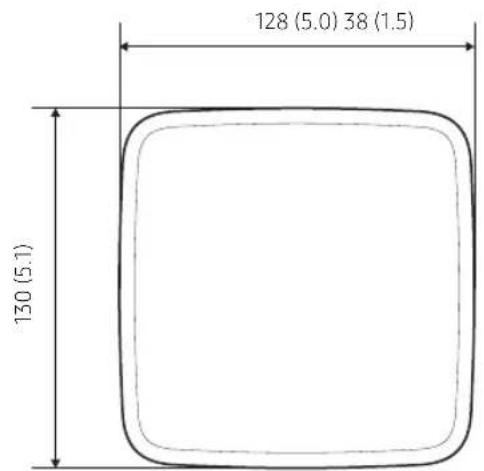
Unit: mm (inch)
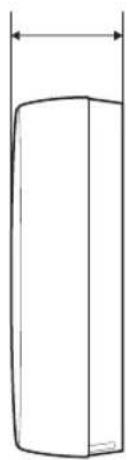
natural_image
Simple line drawing of a cylindrical object with a vertical dimension line (no text or symbols)Checklist Prior to Installation
Product layout
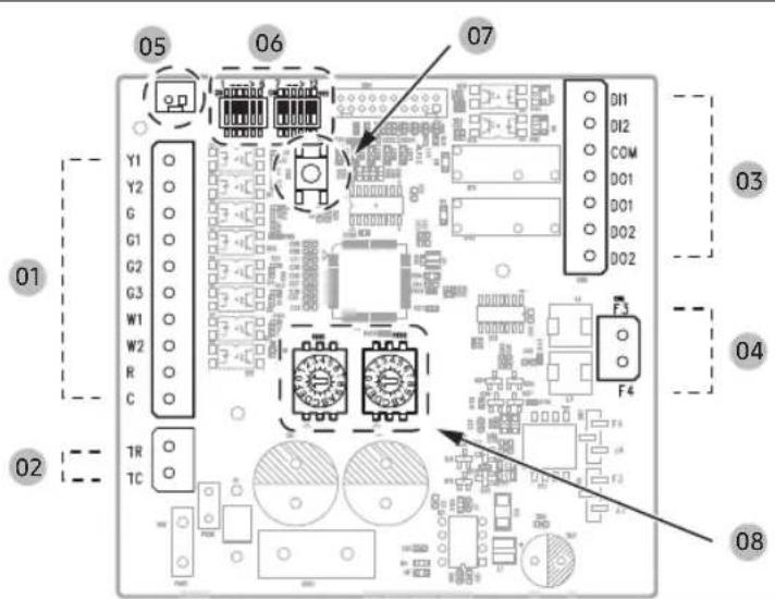
| No. | Name Description | |
| 01 | Y1 Stage 1 cooling input | |
| Y2 Stage 2 cooling input | ||
| G Fan | ||
| G1 | Low Fan input when thermostat has multiple Fan outputs. | |
| G2 | Mid Fan input when thermostat has multiple Fan outputs. | |
| G3 | High Fan input when thermostat has multiple Fan outputs. | |
| W1 Stage 1 heating input | ||
| W2 Stage 2 heating input | ||
| R 24VAC (out) to Thermostat | ||
| C Common (out) to Thermostat | ||
| 02 | TR 24VAC (In) from Transformer | |
| TC Common (In) from Transformer | ||
| No. | Name Description | |
| 03 | DI1 Emergency Input (Optional) | |
| DI2 Not Used | ||
| COM Input Common (Optional) | ||
| DO1 Error Feedback Output (Optional) | ||
| DO1 Error Feedback Output (Optional) | ||
| DO2 | Emergency External Heat Output(Optional) | |
| DO2 | Emergency External Heat Output(Optional) | |
| 04 | F3 | F3, F4 Communication |
| F4 | ||
| 05 | CN7 | External Thermistor Sensor(Optional) |
| 06 | DIP SW DIP Switch (Setting Option Mode) | |
| 07 | SW5 Reset Switch | |
| 08 | RSW1,2 | Rotary Switch(Setting Y1/Y2/W1/W2 Temperature) |

WARNING
- Some Samsung indoor units are not supported. Refer to technical documents at www.SamsungHVAC.com for compatibility details.
English
Installing the Thermostat Kit
Thermostat Kit installation

CAUTION
- When installing the Thermostat Kit, take care while separating the top and bottom sections of the case.
- Do not install the Kit in a location where it may be exposed to moisture or impact.
- Operating temperature: 0^ (32°F) \~ 50°C (122°F) / Relative operating humidity: 10\~85%
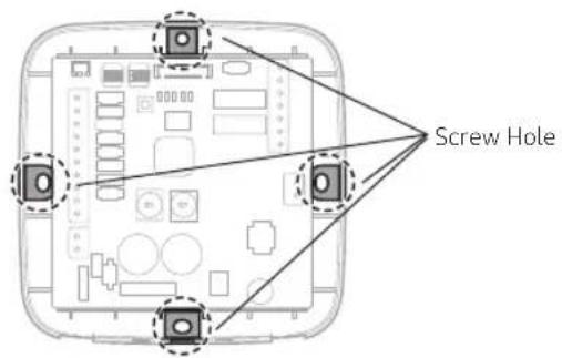
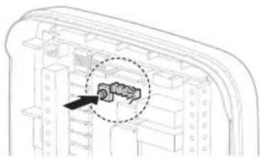
1 Insert a flathead (“-”) screwdriver into the gap at the lower part of the Thermostat Kit indicated in the picture below, turn the screwdriver, and then remove the back cover.
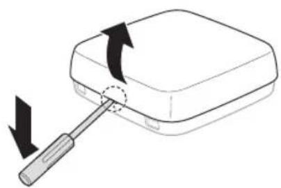
natural_image
Diagram of a screwdriver inserted into a rectangular device with an arrow indicating rotation (no text or symbols present)※ Push the (single) latch.
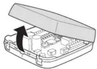
natural_image
Diagram of an open electronic device case with internal components and a black arrow indicating rotation (no text or symbols)
NOTE
- The cover can be easily removed by inserting a flathead (“-”) screwdriver into the gap above the locking hook and turning the screwdriver.
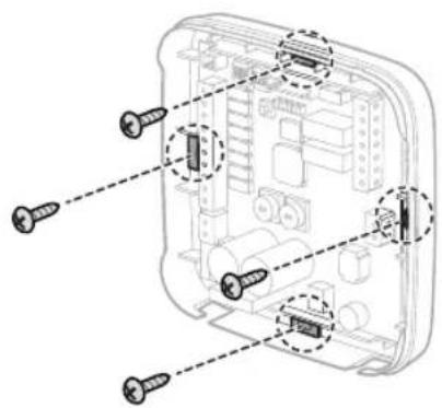
2 Select an installation position after considering the length of the power and communication wires. Use two or more screws to fix the case to the wall.
English 7
Installing the Thermostat Kit
3 Insert the power and communication wires as shown in the figure below, and use a flathead ("-") screwdriver to fix the wires.
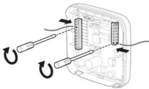
natural_image
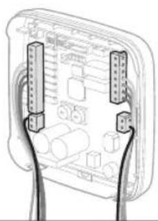
Diagram of cable connector assembly with two connectors and wiring, no text or symbols present4 Insert all of the wires into the holders and secure them together, as shown in the figure.
natural_image
Diagram of two hands holding connectors with circuit board layout (no text or symbols)5 Configure settings according to the environment where the Kit is installed, and confirm that the Kit operates properly.
(※ Refer to "Configuring operation options" and confirm that the Kit operates properly. Turn on or reset after setting.)
8 English
Configuring operation options
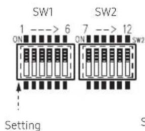
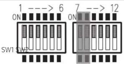
DIP Switch Settings
1) Operation priority setting
- DIP Switch SW1-1: Adjust the operation priority setting according to the follow table.
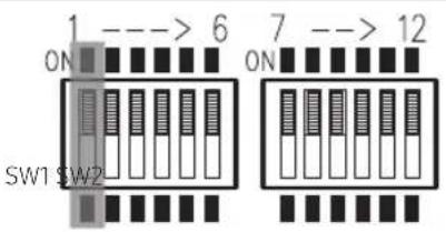
| SW1-1 Operation priority setting | |
| ON Thermostat priority | |
| OFF Basic priority (default) |


WARNING
- Basic priority: Central control and wireless remote control will operate normally. If the indoor unit is controlled by central control or wireless remote control, the displayed indoor status on the thermostat and the actual status of the indoor unit may be different.
- Thermostat priority: The thermostat control will be applied first and will control the indoor unit based on the thermostat demand. Indoor units with this option set to ON will ignore wireless remote control and central control commands including central controller schedule, logic control, etc. Central controllers will only monitor indoor unit status.
Installing the Thermostat Kit
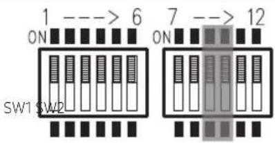
2) External DI / DO Function Setting
- DIP Switch SW1-2/SW1-3: Adjusts the initial setting according to the following table. Select whether to use external input and output.
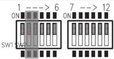
| SW1-2 Use External DI Function |
| ON DI Function enable (dry contact) |
| OFF DI Function disable (default) |
| SW1-3 Use External DO Function | |
| ON DO Function enable | |
| OFF DO Function disable (default) |
3) Error Feedback and External Heater Function Setting
- The digital output function must be enabled (SW1-3 in ON position)
- Enable Error Feedback to provide a dry output signal when the system is in error status.
- Enable Emergency External Heater function to enable external heating devices when an error occurs while the system is in heating thermal-ON. Use when an external "emergency" heater is required.
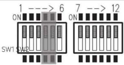
| SW1-4 Select Error Feedback Function | |
| ON Enable Error Feedback | |
| OFF Disable Error Feedback (default) |
| SW1-5 | Select External Heater Function |
| ON | Enable support for external heat |
| OFF | Disable support for external heat (default) |
10 English
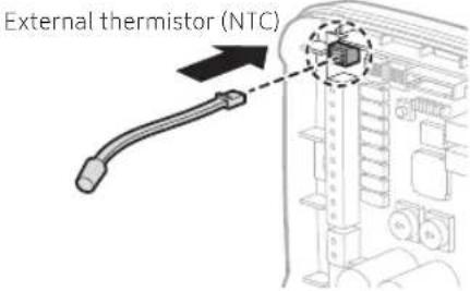
4) External Thermistor (NTC) setting
- This setting allows connection of an optional external thermistor to allow the thermostat kit / Samsung indoor unit to sense room temperature near the 24VAC thermostat.
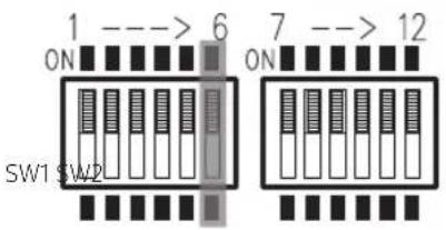
| SW1-6 External Thermistor (NTC) setting | |
| ON Use External Thermistor | |
| OFF Do not use External Thermistor (default) |

CAUTION
- For the external thermistor, use the external room sensor (MRW-TA) supplied by Samsung Electronics.
5) SW2-7, SW2-8 - Two stage heating option when applying hydronic or electric heaters
- Configure the operation of the Samsung indoor unit when there is a heating demand (W1/W2) from the 24VAC thermostat.
| SW2-7 SW2-8 Stage 1, 2 Heat sources option | ||
| ON ON | W1 (Stage 1 heat) energized: SAMSUNG AC OFF | |
| W2 (Stage 2 heat) energized: SAMSUNG AC OFF | ||
| ON OFF | W1 (Stage 1 heat) energized: SAMSUNG AC OFF | |
| W2 (Stage 2 heat) energized: Turn on SAMSUNG AC with Heat Mode | ||
| OFF ON | W1 (Stage 1 heat) energized: Turn on SAMSUNG AC with Fan Mode | |
| W2 (Stage 2 heat) energized: Turn on SAMSUNG AC with Heat Mode | ||
| OFF OFF | W1 (Stage 1 heat) energized: Turn on SAMSUNG AC with Heat Mode (default) | |
| W2 (Stage 2 heat) energized: Turn on SAMSUNG AC with Heat Mode (default) | ||
English 11
Installing the Thermostat Kit
6) SW2-9, SW2-10 - Fan speed setting for 'G' terminal during thermal-ON
- When using a single fan input (G), set the fan speed of the Samsung indoor unit when there is a heating or cooling demand from the 24VAC thermostat (not fan mode only).
| SW2-9 SW2-10 If using ‘G’ Input | |
| ON ON FAN Speed (LOW) | |
| ON OFF FAN Speed (MID) | |
| OFF ON FAN Speed (HIGH) | |
| OFF OFF FAN Speed : Auto (default) |

WARNING
- The "FAN speed: Auto" mode may not work depending on the connected indoor unit. In this situation, use a fixed fan speed (e.g. "HIGH," "MID" or "LOW").
7) SW2-11, SW2-12 - Fan speed setting for 'G' terminal during thermal-OFF
- When using a single fan input (G), set the fan speed of the Samsung indoor unit when there is not a heating or cooling demand from the 24VAC thermostat (fan mode).
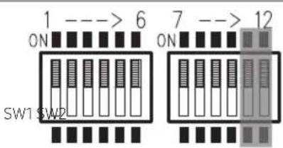
| SW2-11 | SW2-12 | If using ‘G’ Input under thermal off condition |
| ON ON FAN Speed (HIGH) | ||
| ON OFF | FAN Speed (LOW) | |
| OFF ON | FAN Speed (MID) | |
| OFF OFF | FAN Speed (HIGH) (default) | |
12 English
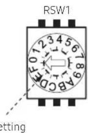
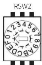
Rotary Switch Functions
- RSW1 sets the indoor unit set temperature for first and second stage cooling inputs (Y1/Y2)
- RSW2 sets the indoor unit set temperature for first and second stage heating inputs (W1/W2)
- Determine average user cooling and heating set temperatures and adjust RSW1 and RSW2 accordingly for optimal comfort after installation.
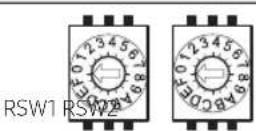
- RSW1: Cool mode set temperature (Y1/Y2), (Cooling: 18°C(64.4°F)\~28°C(82.4°F))
| 0 (default) 1 2 3 4 5 6 7 | |||||||||||||||
| Y1 | Y2 | Y1 | Y2 | Y1 | Y2 | Y1 | Y2 | Y1 | Y2 | Y1 | Y2 | Y1 | Y2 | Y1 | Y2 |
| °C | 23 | 20 | 20 | 18 | 21 | 19 | 22 | 20 | 24 | 22 | 25 | 23 | 26 | 24 | 27 |
| °F | 73.4 | 68 | 68 | 64.4 | 69.8 | 66.2 | 71.6 | 68 | 75.2 | 71.6 | 77 | 73.4 | 78.8 | 75.2 | 80.6 |
| 8 | 9 | A | B | C | D | E | F | |||||||||
| Y1 | Y2 | Y1 | Y2 | Y1 | Y2 | Y1 | Y2 | Y1 | Y2 | Y1 | Y2 | Y1 | Y2 | Y1 | Y2 | |
| °C | 21 | 18 | 22 | 18 | 23 | 18 | 24 | 18 | 25 | 18 | 26 | 18 | 27 | 18 | 28 | 18 |
| °F | 69.8 | 64.4 | 71.6 | 64.4 | 73.4 | 64.4 | 75.2 | 64.4 | 77 | 64.4 | 78.8 | 64.4 | 80.6 | 64.4 | 82.4 | 64.4 |
- RSW2: Heat mode set temperature (W1/W2), (Heating: 20°C(68°F)\~30°C(86°F))
| 0 (default) 1 2 3 4 5 6 7 | |||||||||||||||
| W1 W2 | W1 | W2 W1 | W2 W1 | W2 W1 | W2 | W1 | W2 W1 | W2 | W2 | ||||||
| 22 | 25 | 21 | 24 | 23 | 26 | 25 | 28 | 26 | 29 | 27 | 30 | 20 | 30 | 21 | 30 |
| 71.6 | 77 | 69.8 | 75.2 | 73.4 | 78.8 | 77 | 82.4 | 78.8 | 84.2 | 80.6 | 86 | 68 | 86 | 69.8 | 86 |
| 8 | 9 | A | B | C | D | E | F | |||||||||
| W1 W2 | W1 W2 W1 | W2 W1 | W2 W1 | W2 W1 | W2 W1 | W2 | ||||||||||
| °C | 22 | 30 | 23 | 30 | 24 | 30 | 25 | 30 | 22 | 25 | ||||||
| °F | 71.6 | 86 | 73.4 | 86 | 75.2 | 86 | 77 | 86 | 78.8 | 86 | 82.4 | 86 | 71.6 | 77 | ||
WARNING
- The indoor unit may not operate properly if it is set to "discharge air temperature" control. If this situation is encountered, change the setting to "indoor temperature" control (default indoor unit setting).
English 13
Installing the Thermostat Kit
Inspecting the Thermostat Kit
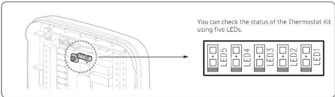
| LED 5 (Amber) | LED 4 (Amber) | LED 3 (Amber) | LED 2 (RED) | LED 1 (GRN) | Condition of thermostat kit |
| Blinking Blinking Blinking Blinking Initial Mode | |||||
| Off Off Off Off On Normal Mode | |||||
| Off Off On Blinking Off | Indoor unit ↔ Thermostat Kit communication error (Communication Error) | ||||
| Off On Off Blinking Off Indoor unit tracking error | |||||
| On Off Off Blinking Off | Error in the installation of multiple Thermostat Kits | ||||
| Off On On Blinking Off | Error in the installation of multiple indoor units | ||||
| On Off On Blinking Off | External thermistor error (External NTC Error) | ||||
| Off Off Blinking Blinking Off | Abnormal thermostat signal (Abnormal W,Y Signal) | ||||
| Off On Blinking Blinking Off | Abnormal thermostat signal (Abnormal W,Y Stage1,2 signal) | ||||
| On Off Blinking Blinking Off | Abnormal thermostat signal (Abnormal G, G1, G2, G3 Signal) | ||||
| On On Blinking Blinking Off Dry contact Input (Close) | |||||
Resetting custom settings
To reset the Thermostat Kit settings, press the (SW5) button inside the kit.
When pressed the Thermostat Kit resets then enters "initial mode", and then returns to normal operation.
Reset (Reset switch) → Initial Mode → Normal Mode
natural_image
Technical diagram of a mechanical component with a highlighted section (no text or symbols)- Initial Mode
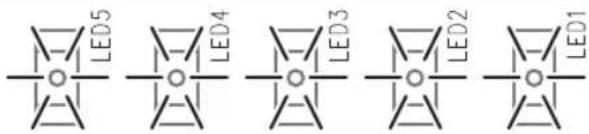
LED1 to LED5 illuminate for 1 second and then turn off for 1 second repeatedly, while the Kit is checking the settings for the DIP Switch and Rotary Switch and checking the communication with the indoor unit.
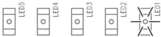
- Normal Mode
The settings and the normal communication status are fixed, and only LED1 remains lit.

CAUTION
• Operation option settings that have been fixed cannot be changed.
Installing the Thermostat Kit
Wiring Examples
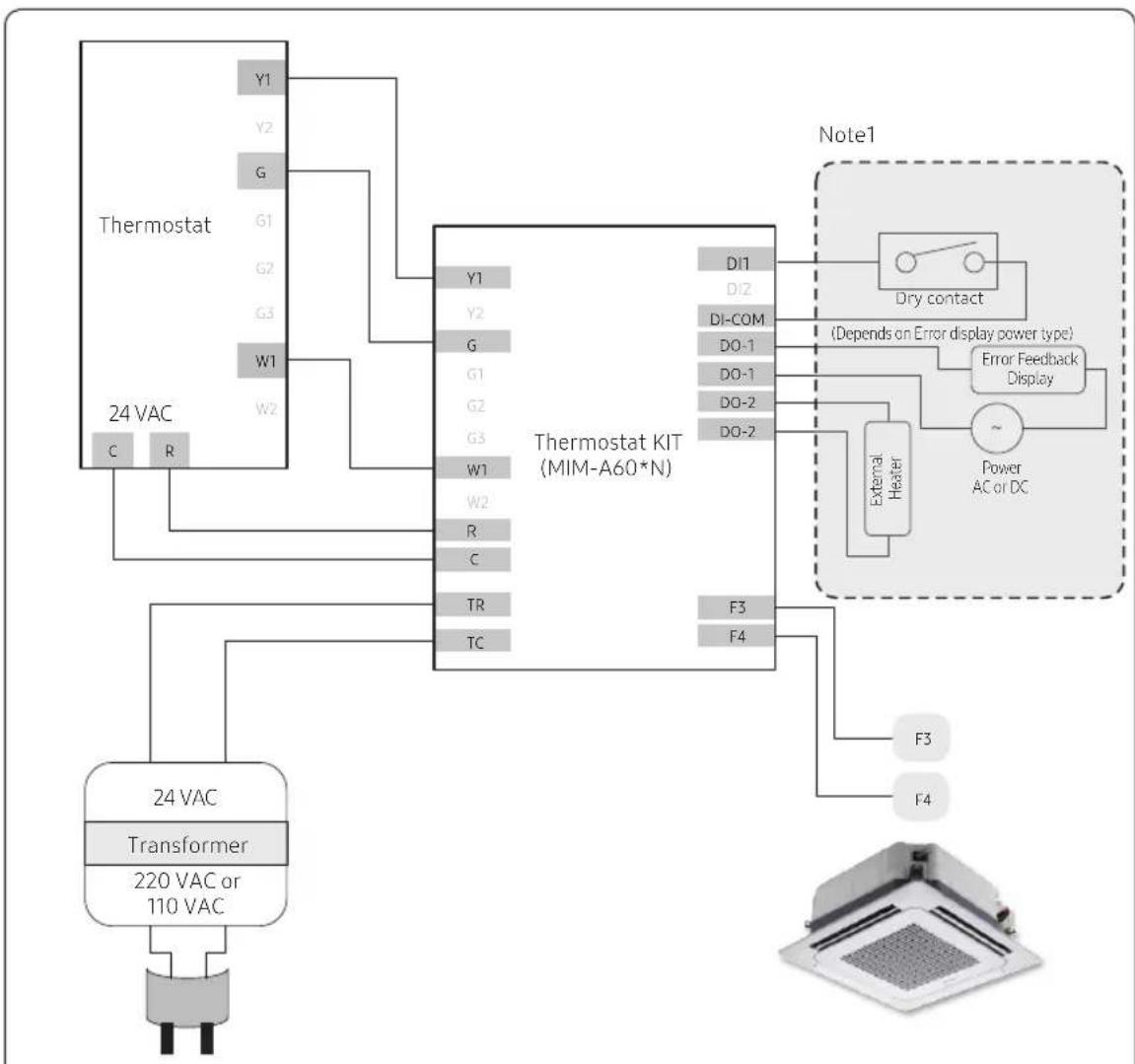
flowchart
graph TD
    A["Thermostat"] -->|Y1 Y2 G G1 G2 G3 W1 W2 C R| B["24 VAC"]
    B --> C["Transformer"]
    C --> D["220 VAC or 110 VAC"]
    D --> E["24 VAC"]
    F["Note1"] --> G["Dry contact"]
    G --> H["Error Feedback Display"]
    H --> I["Power AC or DC"]
    I --> J["External Heater"]
    J --> K["F3 F4"]
    K --> L["Thermostat KIT (MIM-A60*N)"]
    M["Note1"] --> N["Dry contact"]
    N --> O["Error Feedback Display"]
    O --> P["Power AC or DC"]
Fig 1. One-stage cooling and heating
Note1: Adjust the following settings: Dry Contact, Error Feedback, External Heater
Wiring Examples
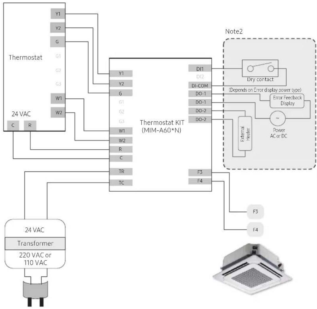
flowchart
graph TD
    A["Thermostat"] -->|Y1 Y2 G| B["24 VAC"]
    A -->|W1 W2| C["Thermostat KIT (MIM-A60*N)"]
    C --> D["Note2"]
    D --> E["Dry contact"]
    E --> F["Error Feedback Display"]
    F --> G["External Heater"]
    G --> H["Power AC or DC"]
    C --> I["Transformer"]
    I --> J["24 VAC"]
    C --> K["TR TC"]
    C --> L["F3 F4"]
    style A fill:#f9f,stroke:#333
    style B fill:#ccf,stroke:#333
    style C fill:#cfc,stroke:#333
    style D fill:#fcc,stroke:#333
    style E fill:#cff,stroke:#333
    style F fill:#ffc,stroke:#333
    style G fill:#cfc,stroke:#333
    style H fill:#fcc,stroke:#333
    style I fill:#cfc,stroke:#333
    style J fill:#fcc,stroke:#333
    style K fill:#cfc,stroke:#333
    style L fill:#fcc,stroke:#333
Fig 2. Two-stage cooling and heating
Note 2: Adjust the following settings: Emergency Input, Emergency External Heater, External Heater
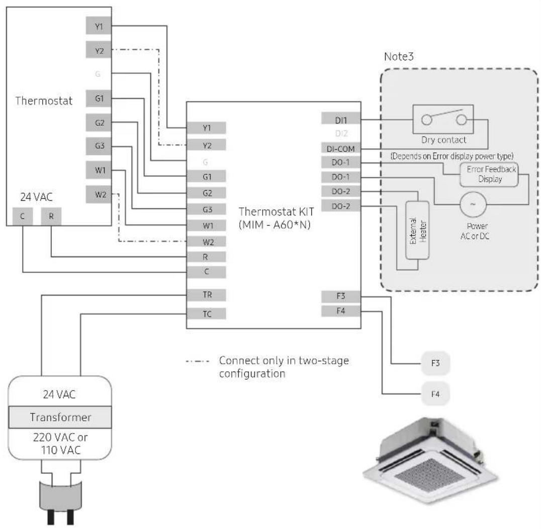
Installing the Thermostat Kit
Wiring Examples
flowchart
graph TD
    A["Thermostat"] -->|Y1 Y2 G G1 G2 G3 W1 W2 C R| B["Thermostat KIT (MIM - A60*N)"]
    B -->|Y1 Y2 G G1 G2 G3 W1 W2 R C TR TC| C["Note3"]
    C --> D["Dry contact"]
    C --> E["Error Feedback Display"]
    C --> F["External Heater"]
    F --> G["Power AC or DC"]
    D --> H["Connect only in two-stage configuration"]
    E --> H
    F --> H
    H --> I["Transformer 24 VAC"]
    I --> J["220 VAC or 110 VAC"]
    J --> K["Output"]
Fig 3. One or Two Stage cooling and heating, with dedicated fan speed control
Note 3: Adjust the following settings: Emergency Input, Emergency External Heater, External Heater
Troubleshooting
| Symptom Measure | |
| The thermostat kit does not work at all.(No LED lighting) | Check the power supply wiring (AC 24V).This connects to F3/F4 enabling central control should not matter. |
| Cooling does not work. Check the wirings for power supply (AC 24V) and communication. | |
| Heating does not work. Check the wirings and options for power supply (AC 24V) and communication. | |
| The desired fan operation does not match. | Check the option setting. |
| The thermostat temperature setting is different from that of the thermostat kit. | Check the rotary switch setting. |

SAMSUNG


Aire acondicionado
natural_image
Simple line drawing of a cylindrical object with a vertical gap, no text or symbols presentnatural_image
Diagram of a screwdriver inserted into a rectangular device with an arrow indicating rotation (no text or symbols present)natural_image
Diagram of an open electronic device casing with internal components and a black arrow indicating rotation (no text or symbols)
NOTA
natural_image
Diagram of a device with two connectors and wiring, showing internal components without any text or symbolsnatural_image
Diagram of two hands holding connectors with circuit board layout (no text or symbols)8 Español
natural_image
Technical diagram of a mechanical assembly with a highlighted component (no text or symbols)- Modo inicial
natural_image
Simple line drawing of a cylindrical object with a vertical dimension line (no text or symbols)natural_image
Diagram of a screwdriver pressing down on a rectangular device with an arrow indicating rotation (no text or symbols present)natural_image
Diagram of an open electronic device casing with internal components and a black arrow indicating rotation (no text or symbols)
REMARQUE
natural_image
Diagram of a device with two connectors and cable routing, showing internal components and wiring (no text or symbols)natural_image
Diagram of two hands connecting to a circuit board with connectors (no text or symbols visible)8 Français
natural_image
Technical diagram of a mechanical assembly with a highlighted component (no text or symbols)- Mode initial
natural_image
Simple line drawing of a cylindrical object with a vertical dimension line (no text or symbols)natural_image
Diagram of a screwdriver inserted into a rectangular device with an arrow indicating rotation (no text or symbols present)natural_image
Diagram of an open electronic device casing with internal components and a black arrow indicating rotation (no text or symbols)
NOTA
natural_image
Diagram of a device with two connectors and cable routing, showing internal components and wiring (no text or symbols)natural_image
Diagram of two hands holding connectors with circuit board layout (no text or symbols)The image is too blurry to recognize any text content.
The image is too blurry to recognize any text content.
2
23
,
a
A
√
-
- RSW1: Temperatura fixa do modo de frio (Y1/Y2), (arrefecimento: 18°C(64,4°F) a 28°C(82,4°F))
| 0 (predefinição) | 1 2 3 4 5 6 7 | ||||||||||||||
| Y1 | Y2 | Y1 | Y2 | Y1 | Y2 | Y1 | Y2 | Y1 | Y2 | Y1 | Y2 | Y1 | Y2 | Y1 | Y2 |
| 23 | 20 | 20 | 18 | 21 | 19 | 22 | 20 | 24 | 22 | 25 | 23 | 26 | 24 | 27 | 25 |
| 73,4 | 68 | 68 | 64,4 | 69,8 | 66,2 | 71,6 | 68 | 75,2 | 71,6 | 77 | 73,4 | 78,8 | 75,2 | 80,6 | 77 |
| 8 | 9 | A | B | C | D | E | F | ||||||||
| Y1 | Y2 | Y1 | Y2 | Y1 | Y2 | Y1 | Y2 | Y1 | Y2 | Y1 | Y2 | Y1 | Y2 | Y1 | Y2 |
| 21 | 18 | 22 | 18 | 23 | 18 | 24 | 18 | 25 | 18 | 26 | 18 | 27 | 18 | 28 | 18 |
| 69.8 | 64.4 | 71.6 | 64.4 | 73.4 | 64.4 | 75.2 | 64.4 | 77 | 64.4 | 78.8 | 64.4 | 80.6 | 64.4 | 82.4 | 64.4 |
- RSW2 : Temperatura fixa do modo de aquecimento (W1/W2), (aquecimento: 20°C(68°F) a 30°C(86°F))
| 0 (predefinição) | 1 2 3 4 5 6 7 | ||||||||||||||
| W1 | W2 | W1 | W2 | W1 | W2 | W1 | W2 | W1 | W2 | W1 | W2 | W1 | W2 | W1 | W2 |
| 22 | 25 | 21 | 24 | 23 | 26 | 25 | 28 | 26 | 29 | 27 | 30 | 20 | 30 | 21 | 30 |
| 71,6 | 77 | 69,8 | 75,2 | 73,4 | 78,8 | 77 | 82,4 | 78,8 | 84,2 | 80,6 | 86 | 68 | 86 | 69,8 | 86 |
| 8 | 9 | A | B | C | D | E | F | |||||||||
| W1 | W2 | W1 | W2 | W1 | W2 | W1 | W2 | W1 | W2 | W1 | W2 | W1 | W2 | W1 | W2 | |
| °C | 22 30 23 | 30 24 30 | 25 30 | 26 30 28 | 30 22 25 | 22 25 | ||||||||||
| °F | 71,6 | 86 | 73,4 | 86 | 75,2 | 86 | 77 | 86 | 78,8 | 86 | 82,4 | 86 | 71,6 | 77 | 71,6 | 77 |
AVISO
natural_image
Technical diagram of a mechanical component with a highlighted section (no text or symbols)- Modo inicial
- Contents
- Safety Information 3
- Checklist Prior to Installation 5
- Installing the Thermostat Kit 7
- Safety Information
- WARNING
- CAUTION
- Checklist Prior to Installation
- Accessories
- External Dimensions
- Product layout
- Installing the Thermostat Kit
- Thermostat Kit installation
- NOTE
- Configuring operation options
- DIP Switch Settings
- 1) Operation priority setting
- 2) External DI / DO Function Setting
- 3) Error Feedback and External Heater Function Setting
- 4) External Thermistor (NTC) setting
- Rotary Switch Functions
- Inspecting the Thermostat Kit
- Resetting custom settings
- Wiring Examples
- Troubleshooting
- SAMSUNG
- Aire acondicionado
- NOTA
- REMARQUE
- AVISO
Brand : SAMSUNG
Model : MIM-A60N
Category : Air conditioner