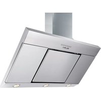
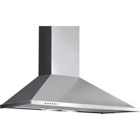
ELIO 9366 - Range hood Elba - Free user manual and instructions
Find the device manual for free ELIO 9366 Elba in PDF.


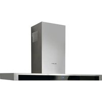
| Product type | Kitchen hood |
| Brand | Elba |
| Model | ELIO 9366 |
| Category | Extractor or recirculation hood |
| Minimum distance between hood and cooking surface | 45 cm (for electric, gas or induction hobs) |
| Operating modes | External extraction, recirculation (activated carbon filter), external motor |
| Number of speeds | 3 speeds + intensive speed (10 minutes) |
| Special functions | Automatic shutdown timer (15 min), Clean Air function (10 min/h), filter saturation indicator |
| Lighting | Halogen lamps (type to check on the appliance) |
| Filters | Metal grease filter (washable), activated carbon filter (non-regenerable or regenerable depending on model) |
| Maintenance of grease filters | Hand or dishwasher cleaning every 2 months maximum |
| Maintenance of non-regenerable activated carbon filters | Replacement every 4 months maximum |
| Maintenance of regenerable activated carbon filters | Machine wash at 65°C, oven drying at 100°C, replacement every 3 years |
| Cleaning the hood | With a damp cloth and neutral non-abrasive detergent |
| Safety | Never flambé under the hood, do not leave open flames, monitor frying, disconnect before maintenance |
| Installation | Wall mounting by a professional, respect safety distance, provide an opening for extraction |
| Power supply | 230 V ~ 50 Hz (check on the rating plate) |
| Insulation class | Class II (double insulation, no earth wire) |
| Available options | Decorative chimneys, soundproofing kit |
| General information | User and installation manual included; comply with local regulations for disposal |
Frequently Asked Questions - ELIO 9366 Elba
User questions about ELIO 9366 Elba
0 question about this device. Answer the ones you know or ask your own.
Ask a new question about this device
Download the instructions for your Range hood in PDF format for free! Find your manual ELIO 9366 - Elba and take your electronic device back in hand. On this page are published all the documents necessary for the use of your device. ELIO 9366 by Elba.
USER MANUAL ELIO 9366 Elba
Fig.3
Fig.2

natural_image
Illustration of a printer's paper feeding into a tray, showing hands and a curved arrow indicating rotation (no text or symbols)Fig.4.1 Fig.4.2
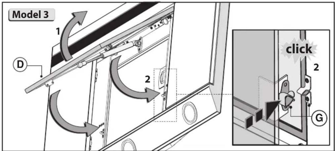
Fig.4.3
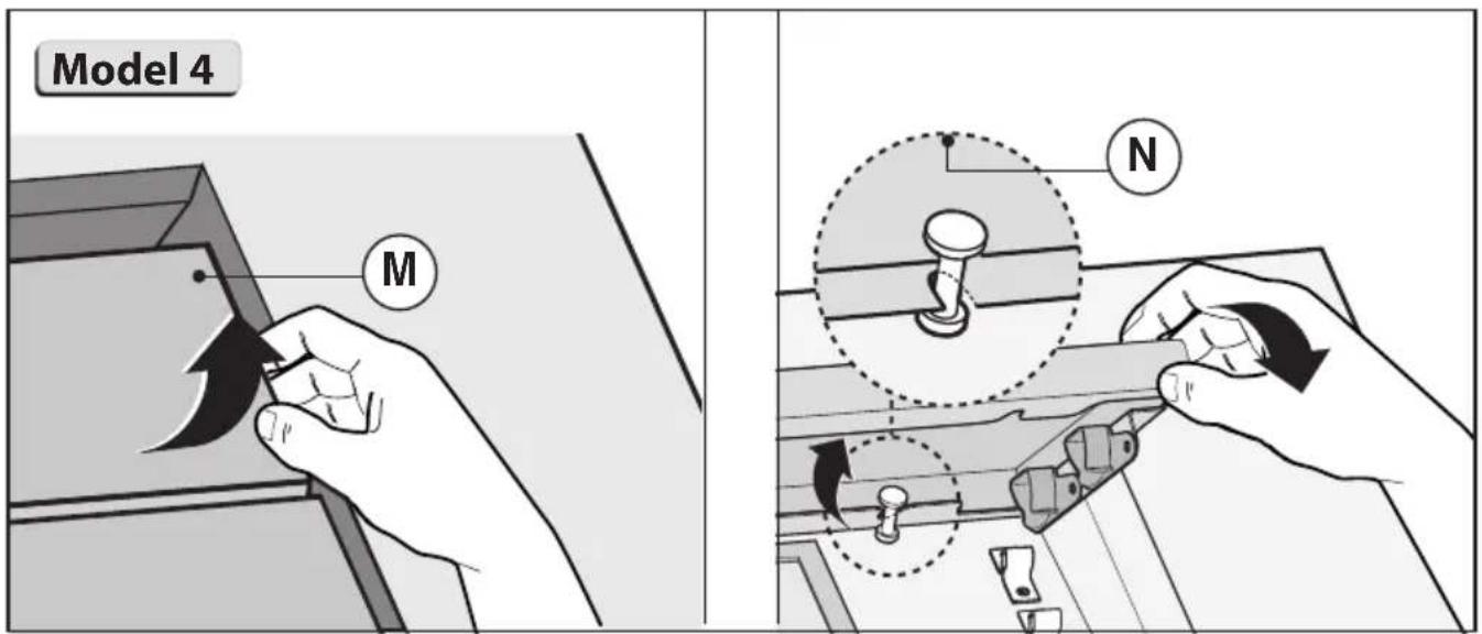
Fig.4.4
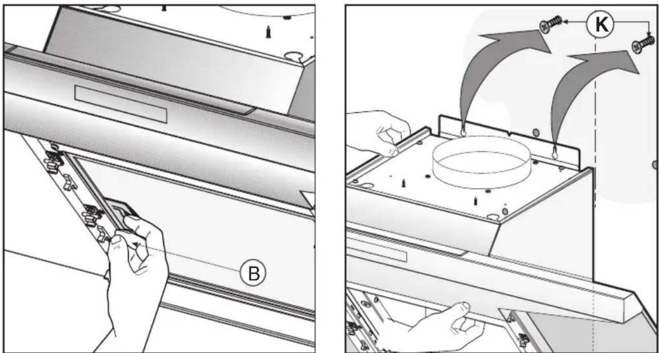
Fig.6 Fig.7
natural_image
Technical diagram of a mechanical assembly with tool and component labels (no readable text or symbols)Fig.8
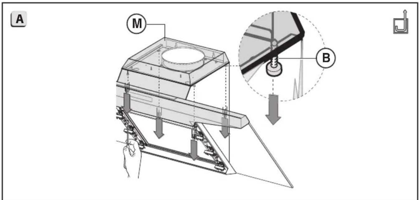
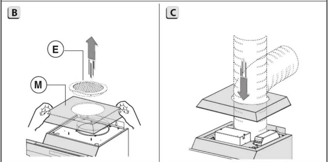
Fig.9
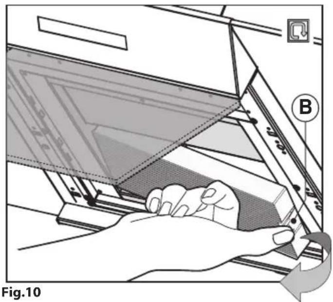
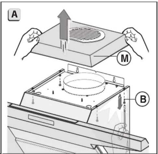
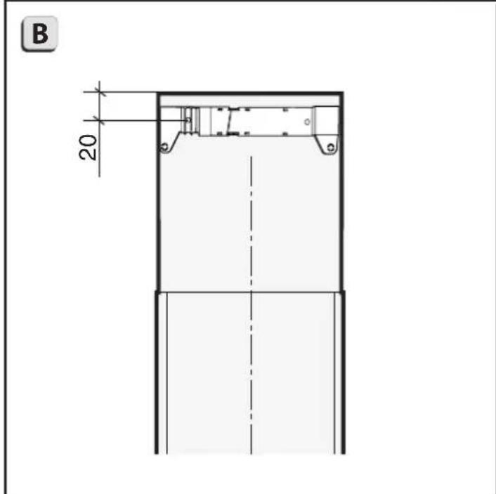
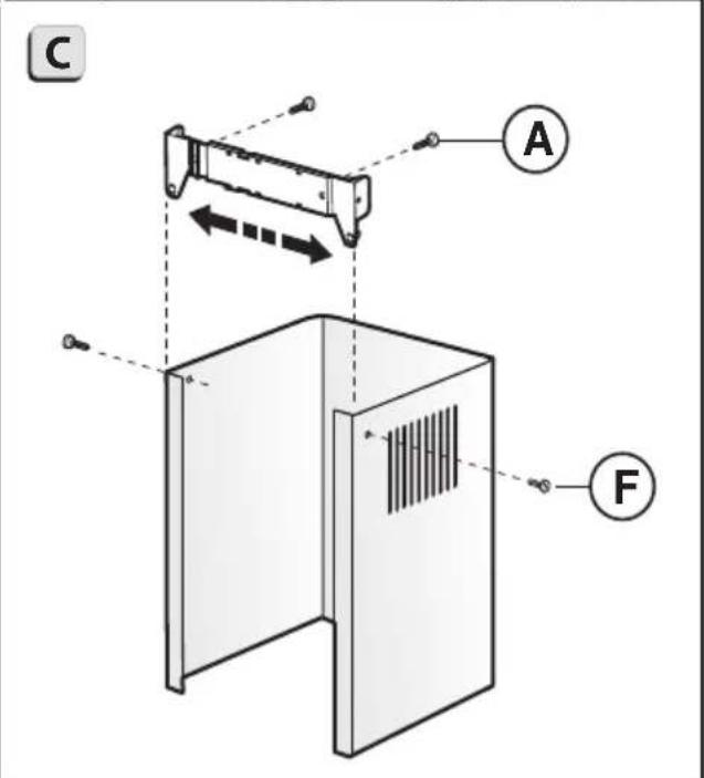
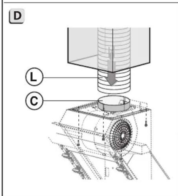
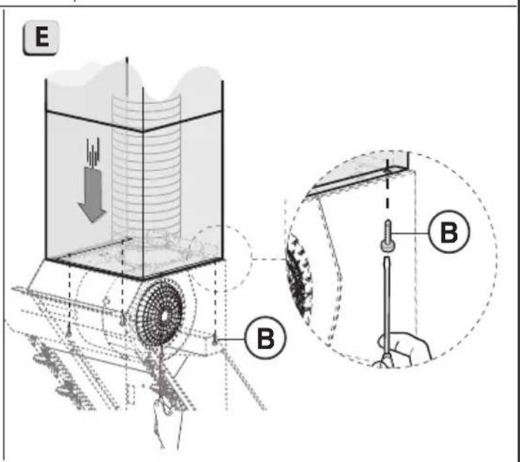
Fig.11
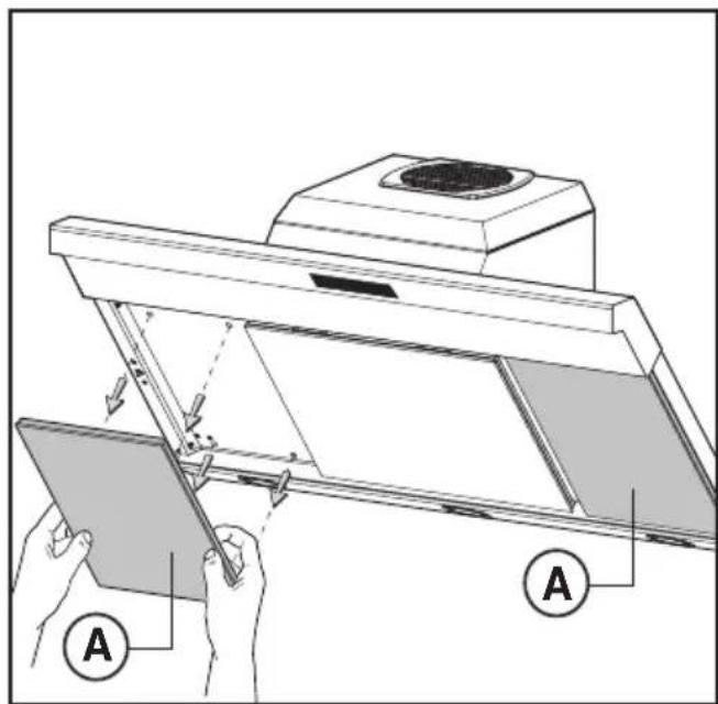
Fig.12
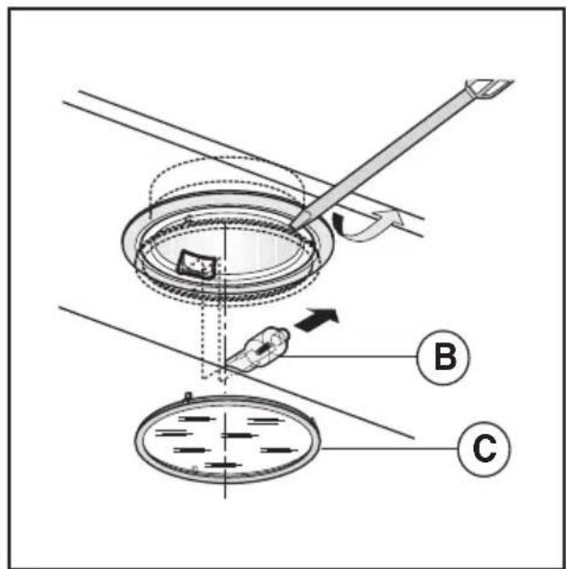
Fig.13
natural_image
Technical diagram of a mechanical assembly with directional arrows indicating motion or force (no text or symbols present)Fig.14
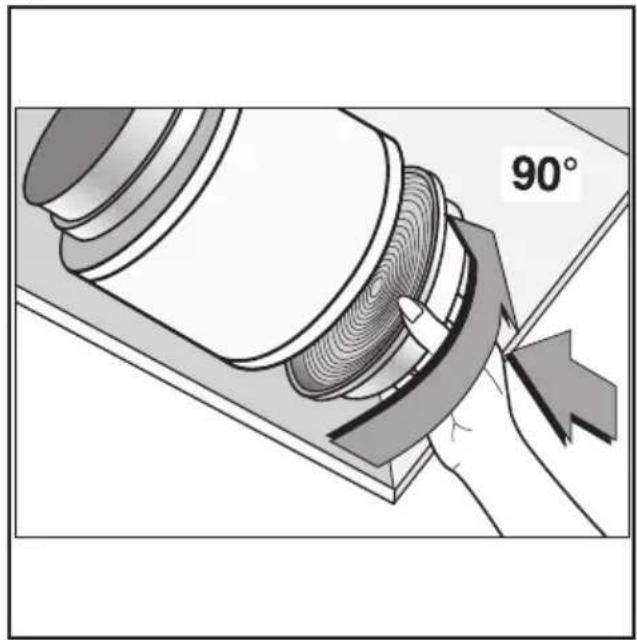
Fig.15
flowchart
graph TD
    A["Sun Icon"] --> B["A"]
    C["0"] --> D["B"]
    E["1"] --> F["C"]
    G["2"] --> H["D"]
    I["3"] --> J["E"]
    K["T"] --> L["F"]
Fig.16 Fig.17
GENERALITÀ
- Commandes (Fig.17):
Carefully read the following important information regarding installation safety and maintenance. Keep this information booklet accessible for further consultations. The appliance has been designed for use in the ducting version (air exhaust to the outside - Fig.1B), filtering version (air circulation on the inside - Fig.1A) or with external motor (Fig.1C).
SAFETY PRECAUTION
- Take care when the cooker hood is operating simultaneously with an open fireplace or burner that depend on the air in the environment and are supplied by other than electrical energy, as the cooker hood removes the air from the environment which a burner or fireplace need for combustion. The negative pressure in the environment must not exceed 4Pa (4x10⁻⁵ bar). Provide adequate ventilation in the environment for a safe operation of the cooker hood. Follow the local laws applicable for external air evacuation.
Before connecting the model to the electricity network:
- Control the data plate (positioned inside the appliance) to ascertain that the voltage and power correspond to the network and the socket is suitable. If in doubt ask a qualified electrician.
- If the power supply cable is damaged, it must be replaced with another cable or a special assembly, which may be obtained direct from the manufacturer or from the Technical Assistance Centre.
- This device must be connected to the supply network through either a plug fused 3A or hardwired to a 2 fase spur protected by 3A fuse.
2. Warning!
In certain circumstances electrical appliances may be a danger hazard.
A) Do not check the status of the filters while the cooker hood is operating.
B) Do not touch bulbs or adjacent areas, during or straight after prolonged use of the lighting installation.
C) Flambè cooking is prohibited underneath the cooker hood.
D) Avoid free flame, as it is damaging for the filters and a fire hazard.
E) Constantly check food frying to avoid that the overheated oil may become a fire hazard.
F) Disconnect the electrical plug prior to any maintenance.
G) This appliance is not intended for use by young children or infirm persons without supervision.
H) Young children should be supervised to ensure they do not play with the appliance.
I) There shall be adequate ventilation of the room when the rangehood is used at the same time as appliances burning gas or other fuels.
L) There is a risk of fire if cleaning is not carried out in accordance with the instructions.
This appliance conforms to the European Directive EC/2002/96, Waste Electrical and Electronic Equipment (WEEE). By making sure that this appliance is disposed of in a suitable manner, the user is helping to prevent potential damage to the environment or to public health.

The symbol on the product or on the accompanying paperwork indicates that the appliance should not be treated as domestic waste, but should be delivered to a suitable electric and electronic appliance recycling collection point. Follow local guidelines when disposing of waste. For more information on the treatment, re-use and recycling of this product, please contact your local authority, domestic waste collection service or the shop where the appliance was purchased.
INSTALLATION INSTRUCTIONS
- Assembly and electrical connections must be carried out by specialised personnel.
- Wear protective gloves before proceeding with the installation.
• Electric Connection:
Insulation class II
- The appliance has been manufactured as a class II, therefore no earth cable is necessary.
The plug must be easily accessible after the installation of the appliance.
If the appliance is equipped with power cord without plug, a suitably dimensioned omnipolar switch with 3 mm minimum opening between contacts must be fitted between the appliance and the electricity supply in compliance with the load and current regulations.
- The connection to the mains is carried out as follows:
BROWN = L line
BLUE = N neutral.
- The distance between the supporting surface of the cooking appliance on which the cooking recipients are placed and the lower part of the kitchen hood must be a minimum of 45cm , whether it is an electric hob, a gas hob or an induction hob. If a connection tube composed of two parts is used, the upper part must be placed outside the lower part. Do not connect the cooker hood exhaust to the same conductor used to circulate hot air or for evacuating fumes from other appliances generated by other than an electrical source.
- In the case of assembly of the appliance in the suction version prepare the hole for evacuation of the air.
- We recommend the use of an air exhaust tube which has the same diameter as the air exhaust outlet hole. If a pipe with a smaller diameter is used, the efficiency of the product may be reduced and its operation may become noisier.
- Before starting to fix the hood, disconnect the anti-grease filter B (Fig.6) for easier appliance handling.
Before this operation, perform the following steps depending on the model purchased:
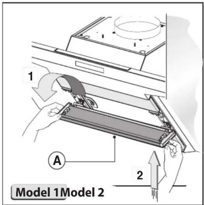
Model 1
Remove the 3 panels A as shown in Fig.4.1.
Pull handle B as shown in Fig.6.
Model 2
Open panel C as shown in Fig.4.2.
Pull handle B as shown in Fig.6.
Model 3
Remove the 3 panels D as shown in Fig.4.3
Pull handle B as shown in Fig.6.
When closing the panel, make sure that it is perfectly hooked on to the fastening pins G fig.4.3.
Model 4
If one owns the version with three A panels release them from the fixing pins by pulling outwards (Fig.4.4) and then remove them from safety pins N (Fig.4.4) placed inside the hood.
Pull handle B as shown in Fig.6. To put them back perform the operation in reverse order. ATTENTION! During this disassembly and assembly operation ensure to hold the panel securely to prevent accidental falls.
- If the appliance has a lid, remove it by removing the 4 screws B as shown in Fig.9A.
- Wall fixing
Mark the position of the lower side of the hood on the wall (Fig.2A). Maintain the minimum distance required from the hob as shown in Fig.2B.
- Position the fixing template on the wall, making sure that the line coincides with the line previously made on the wall.
- Mark the fixing holes and cut them into the material (Fig.3).
- Fix the 2 top screws K and screw anchors (Fig.3), without tightening them completely.
- Place the appliance against the wall, align it in horizontal position and tighten screws K (Fig.7).
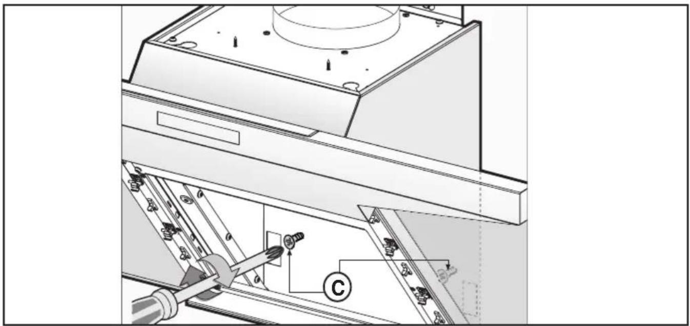
- Once the adjustment has been completed, fix the hood using the 2 screws C (Fig.8).
- When carrying out the fixing operations, use only screws and screw anchors suited to the type of wall (e.g. reinforced concrete, plasterboard etc.).
- If the screws and screw anchors are supplied with the appliance, make sure that they are suited to the type of wall to which the hood must be fixed.
- Installation of models without decorative ducts - extractor hood
- Remove the 4 screws B as shown in (Fig.9 A).
- Remove both grid E on the air outlet hole and lid M as shown in (Fig.9 B).
- Connect the hood to the flexible hose (not supplied) and the hose to the air exhaust hole previously prepared (Fig.9 C).
- Fix the lid once again by using the 4 screws previously removed in (Fig.9 A).
- Optional accessories
- This model may have decorative ducts as optional accessories
- ask your retailer for information.
Before fixing the decorative ducts, remove both the 4 screws B and lid M, as shown in (Fig.10A-B). - A sound-absorbing kit is also available (to be ordered as an OPTIONAL accessory) in order to increase the quietness level of the hood. The sound-absorbing layer must be applied to the back of the decorative panel. For fixing operations, refer to the instructions supplied with the kit.
• Installation of models with decorative ducts
Make sure the electrical power supply is within the measurements of the decorative connector.
Adjust the width of the support bracket of the top connector (Fig.11C). Then fix it to the ceiling so that it is on the same axis as the hood using screws A (Fig.11C) adhering to the distance
from the ceiling shown in (Fig.11B). Connect flange C to the air exhaust hole using flexible hose L (Fig.11D).
Slide the top duct into the bottom duct. Fix the bottom duct to the hood using screws B (supplied) (Fig.11E).
Pull out the top duct as far as the bracket and fix it using screws F (Fig.11C).
- Filter hood
Please note:
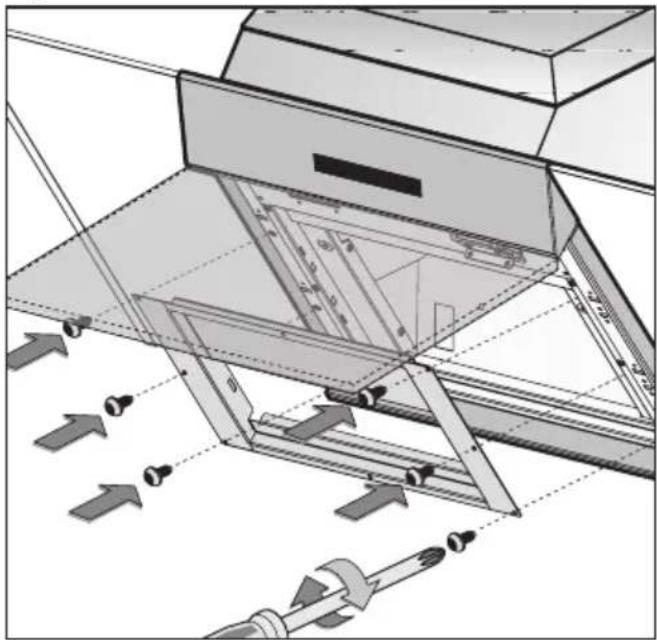
The filters should be ordered as accessories from your retailer. We offer 2 different types of kit which can be used to transform the EXTRACTOR hood into a FILTER hood, in accordance with the type of appliance model purchased. One kit contains extractable filters (fig. 10) and the other contains circular filters (fig. 15).
1- If you find a bracket (such as the one indicated in fig. 14) included in the product packaging, this should be fixed to the hood using the 6 screws supplied.
To replace the active carbon filters pull lever B outwards as shown in (Fig.10).
2- If your product is not supplied with a bracket, this means that the active carbon filter is a circular version (fig. 15).
The filters should be fitted to the extraction assembly inside the hood, by centring them and rotating them 90 degrees, until they click into place (Fig. 15).
USE AND MAINTENANCE
• We recommend that the cooker hood is switched on before any food is cooked. We also recommend that the appliance is left running for 15 minutes after the food is cooked, in order to thoroughly eliminate all contaminated air.
The effective performance of the cooker hood depends on constant maintenance; the anti-grease filter and the active carbon filter both require special attention.
- The anti-grease filter is responsible retaining the grease particles suspended in the air, therefore it is subject to clogging with variable frequency according to the use of the appliance.
- To prevent the danger of possible fires, at least every 2 months one must wash the anti-grease filters by hand using non-abrasive neutral liquid detergents or in the dishwasher at low temperatures and on short cycles.
- After a few washes, colour alterations may occur. This does not give the right to claim their replacement.
- The active carbon filters are used to purify the air that is sent back into the room and its function is to mitigate the unpleasant odours produced by cooking.
- The non-regenerable active carbon filters must be replaced at least every 4 months. The saturation of the active charcoal depends on the more or less prolonged use of the appliance, on the type of kitchen and on the frequency with which anti-grease filter is cleaned.
- Regenerable active charcoal filters must be washed by hand, with non abrasive neutral detergents, or in the dishwasher at a maximum temperature of 65^ C (the washing cycle must be complete without dishware). Remove excess water without damaging the filter, remove the plastic parts, and let the mat dry in the oven for at least 15 minutes approximately at a maximum temperature of 100^ C. To keep the regenerable charcoal filter functioning efficient this operation must be repeated every 2 months. These must be replaced at least every 3 years or when the mat is damaged.
- Before remounting the anti-grease filters and the regenerable active charcoal filters it is important that they are completely dry.
- Clean the hood frequently, both internally and externally,
using a cloth dampened with water or non-abrasive neutral liquid detergents.
- The lighting .system is designed for use during cook and not for the prolonged general lighting of the room. The prolonged use of the lighting system significantly decreases the average duration of the bulbs.
- If the appliance is equipped with courtesy lights it is possible to use them for general room lighting for a prolonged amount of time.
- Attention: the non compliance with the hood cleaning warnings and with the replacement and cleaning of the filters entails risk of fires. One therefore recommends keeping to the suggested instructions.
- Replacing halogen light bulbs (Fig.13):
To replace the halogen light bulbs B, remove the glass pane
C using a lever action on the relevant cracks.
Replace the bulbs with new ones of the same type.
Caution: do not touch the light bulb with bare hands.
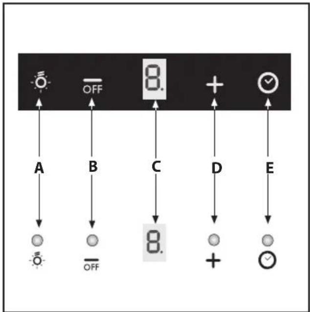
- Commands (Fig.17):
Push-button A = On/off lights switch.
Push-button B = On/off cooker hood switch. The appliance switches on at speed level 1, If the cooker hood is on depress the push-button for 2 sec. to switch off the cooker hood. If the cooker hood is at speed level 1 it will not be necessary to depress the push-button to switch the cooker hood off. Decreases the motor speed.
Display C = Indicates the motor speed level selected and activates the timer.
Push-button D = Switches on the cooker hood. Increases the motor speed. Touching the key at 3rd speed, the intensive function runs for 10', then the appliance go back to work at the original speed. During this function the display blinks.
Key E = The Timer times the functions on activation for 15 minutes, after which they are switched off. The Timer is deactivated by re-pressing Key E.
When the Timer is activated the decimal point must flash on the display. The Timer cannot be activated if the intensive speed is functioning.
The "clean air" function is activated by pressing key E for 2 seconds when the appliance is switched off. This switches the motor on for 10 minutes every hour at the first speed.
During functioning a rotary movement of the peripheral segments must be visualised on the display. When this time has passed the motor switches off and the fixed letter "C" must be visualised on the display until the motor re-starts after 50 minutes for another 10 minutes and so on.
Press any key apart from the light keys to return to normal functioning. Press key E to deactivate the function.
- Anti-grease/active charcoal filters saturation:
- When display item C flashes, at a speed where it alternates with the letter F (e.g. 1 and F), the anti-grease filters must be washed.
- When display item C flashes, at a speed where it alternates with the letter A (e.g. 1 and A), the active carbon filters must be replaced or washed depending on the type of filter.
After the clean filter has been positioned correctly, the electronic memory must be reset by pressing button A for approximately 5 seconds, until the indication F or A shown on the display C stops flashing.
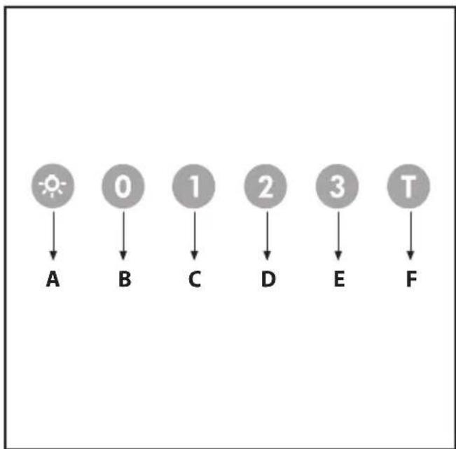
- Commands luminous (Fig.16) the key symbols are explained below:
$$ \mathbf {A} = \text { LIGHT } $$
$$ \mathbf {B} = \text { OFF } $$
$$ \mathbf {C} = \text { SPEEDI } $$
$$ \mathbf {D} = \text { SPEED II } $$
$$ \mathbf {E} = \text { SPEED III } $$
$$ \mathbf {F} = \text { AUTOMATIC STOP TIMER } - 1 5 \text { minutes } (*) $$
If your appliance has the INTENSIVE speed function, from speed THREE, press key E for 2 seconds and it will be activated for 10 minutes after which it will return to the previously set speed.
When the function is active the LED flashes.
To interrupt it before the 10 minutes have elapsed, press key E again.
Some models allow activating this function even with speed one and two.
By pressing key F for two seconds (with the hood switched off) the "clean air" function is activated. This function switches the appliance on for ten minutes every hour at the first speed. As soon as this function is activated the motor starts up at the first speed for ten minutes. During this time key F and key C must flash at the same time. After ten minutes the motor switches off and the LED of key F remains switched on with a fixed light until the motor starts up again at the first speed after fifty minutes and keys F and C start to flash again for ten minutes and so on. By pressing any key for the exclusion of the hood light the hood will return immediately to its normal functioning (e.g. if key D is pressed the "clean air" function is deactivated and the motor moves to the 2nd speed straight away. By pressing key B the function is deactivated).
(*) The "AUTOMATIC STOP TIMER" delays stopping of the hood, which will continue functioning for 15 minutes at the operating speed set at the time this function is activated.
- Anti-grease/active charcoal filters saturation:
- When the A key flashes with a 2 second frequency the anti-grease filters must be washed.
-When the A key flashes with a 0.5 second frequency the active carbon filters must be replaced or washed depending on the type of filter.
Once the clean filter has been put back one must reset the electronic memory by pressing the A key for approximately 5 seconds until it stops flashing.
THE MANUFACTURER DECLINES ALL RESPONSIBILITY FOR EVENTUAL DAMAGES CAUSED BY BREACHING THE ABOVE WARNINGS.
ALGEMEEN
INSTALLATIE INSTRUCTIES
C = Knop EERSTE SNELHEID
D= Knop TWEEDW DERDE SNELHEID
E = Knop DERDE SNELHEID
F = Knop TIMER AUTOMATISCHE ONDERBREKING na 15 minu- ten (*)
Tecla A = Acende/apaga as luzes.
natural_image
Stylized black-and-white graphic with a plant and star-like circles above, resembling a logo or emblem (no text or symbols)
natural_image
Black-and-white map of Europe showing country borders (no text or labels)3LIK1515
- GENERALITÀ
- SAFETY PRECAUTION
- Before connecting the model to the electricity network:
- Warning!
- INSTALLATION INSTRUCTIONS
- • Electric Connection:
- Insulation class II
- Model 1
- Model 2
- Model 3
- Model 4
- - Wall fixing
- - Installation of models without decorative ducts - extractor hood
- - Optional accessories
- • Installation of models with decorative ducts
- - Filter hood
- Please note:
- USE AND MAINTENANCE
- using a cloth dampened with water or non-abrasive neutral liquid detergents.
- - Replacing halogen light bulbs (Fig.13):
- - Commands (Fig.17):
- - Anti-grease/active charcoal filters saturation:
- THE MANUFACTURER DECLINES ALL RESPONSIBILITY FOR EVENTUAL DAMAGES CAUSED BY BREACHING THE ABOVE WARNINGS.
- ALGEMEEN
- INSTALLATIE INSTRUCTIES
Brand : Elba
Model : ELIO 9366
Category : Range hood