
PACB12HP - Air Conditioning WHIRLPOOL - Free user manual and instructions
Find the device manual for free PACB12HP WHIRLPOOL in PDF.

| Product Type | Mobile monobloc air conditioner |
| Brand | Whirlpool |
| Model | PACB12HP |
| Operating Modes | Cooling, Dehumidification, Fan only, Heating |
| Fan Speed | Auto, High, Medium, Low |
| Cooling Capacity | 12000 BTU/h (estimated) |
| Heating Capacity | 12000 BTU/h (estimated) |
| Power Supply | 220-240 V ~ 50 Hz, 20 A fuse |
| Refrigerant | R134a, GWP 2087.5 |
| Remote Control | Yes, with LCD display, AAA batteries (2 x 1.5 V) |
| Special Functions | 6th Sense (automatic), Jet (quick cooling/heating), Sleep (auto-off after 8h), Timer (1-10h), Swing (oscillation), Around U (remote temperature), DIM (lighting) |
| Adjustable Temperature Range | 18 °C to 32 °C (cooling and heating) |
| Installation Type | Window or door, sliding kit included |
| Exhaust Hose Length | 60 to 170 cm |
| Cleaning | Washable air filter with warm water, exterior with soft cloth |
| Drainage | Internal tank with secondary plug and main drain hose |
| Filter Indicator | Lights up after 360h of fan operation |
| Error Code E5 | Water tank full, requires drainage |
Frequently Asked Questions - PACB12HP WHIRLPOOL
User questions about PACB12HP WHIRLPOOL
0 question about this device. Answer the ones you know or ask your own.
Ask a new question about this device
Download the instructions for your Air Conditioning in PDF format for free! Find your manual PACB12HP - WHIRLPOOL and take your electronic device back in hand. On this page are published all the documents necessary for the use of your device. PACB12HP by WHIRLPOOL.
USER MANUAL PACB12HP WHIRLPOOL
Instructions for use
Mode d'emploi
Gebruiksaanwijzing
natural_image
Close-up of three wooden clothespins with metal fittings and a circular hole, no text or symbols visibleBrugsanvisning
Bruksanvisning
Käyttöohje
natural_image
Black and white photo of multiple empty glass bottles with black caps, arranged in a row (no visible text or symbols)
natural_image
Black and white close-up of multiple glasses with no visible text or symbolsΟδηγίες χρήσης
natural_image
Close-up of a white industrial or kitchen appliance with perforated ventilation slots (no visible text or symbols)Návod k použití
Návod na použitie
Signalton ab.
6. TASTE 6TH SENSE (6. SINN)
Auto → High → Medium → Low ↑
natural_image
Technical line drawings of battery components including a cylindrical tube, two rectangular plates, and a multi-pin connector (no text or symbols)natural_image
Diagram showing two views of a storage or storage unit with arrows indicating movement, no text or symbols present.natural_image
Diagram showing two views of a door with directional arrows indicating movement or force (no text or symbols)Please ready all instructions carefully before using this product. When using this appliances, should always follow this instruction to reduce the risk of fire, electric shock, and injury to person.
Please keep this manual. If you deliver the appliance to other users, do handover this manual together.
These instructions shall also be available on website: www.whirlpool.eu.
SAFETY PRECAUTIONS
- The Installation and service/repair must be performed by a qualified technician, in compliance with the producer's instructions and following local safety norms. Do not repair or replace any parts of the appliance unless it is specifically written in the user instructions.
- Do not pull the power supply cord to remove it from the socket. Do not twist or press the power supply cord, and make sure it is not broken.
- Do not touch the power plug, circuit breaker and emergency button when your hands are wet.
- Do not insert your fingers or foreign substances into the air inlet/outlet of indoor&outdoor unit.
- Never block the air inlet or outlet of indoor and outdoor unit.
• Physically or mentally disabled people, children and people without any experience with the product are only allowed to use
the appliance if they have had specific training on how to operate the appliance by a person responsible for their security and well-being. The appliance is not intended for use by disabled people and very young children without supervision.
• Children should be supervised to ensure that they do not play with the appliance (including remote control).
- This appliance can be used by children aged from 8 years and above and persons with reduced physical, sensory or mental capabilities or lack of experience and knowledge if they have been given supervision or instruction concerning use of the appliance in a safe way and understand the hazards involved. Children shall not play with the appliance.
Cleaning and user maintenance shall not be made by children without supervision.
AIR CONDITIONER PRECAUTIONS
Please strictly follow the below instructions:
- Long and direct exposure to cool air might be harmful to health. It is advisable to set the louvers in order to avoid direct cool air and deflect it within the room.
-
Upon malfunctioning first turn the appliance off by pressing the ON/OFF button on the remote control, then disconnect it from power supply.
• Always turn off the air conditioner by remote control first. Do not use the power supply circuit breaker or pull off the plug to turn it off. -
Do not switch the appliance on and off too often as this can damage the appliance.
- Do not place any objects on the outdoor unit.
- Disconnect the air conditioner from the power supply if it is to be left unused for a long period of time or during a thunder/lightning storm.
- This product contains Fluorinated Greenhouse Gases covered by the Kyoto Protocol, the refrigerant gas being in a hermetically sealed system. Refrigerant gas: R410a has a Global Warming Potential (GWP) 2087.5.
SAFEGUARDING THE ENVIRONMENT
- This appliance has been made of recyclable or re-usable material. Scrapping must be carried out in compliance with local waste disposal regulations. Before scrapping it, make sure to cut off the mains cord so that the appliance cannot be re-used.
- For more detailed information on handling and recycling of this product, contact your local authorities who deal with the separate collection of rubbish or the shop where you bought the appliance.
SCRAPPING OF PACKAGING
- The packaging can be 100% recycled as confirmed by the recycling symbol. The various parts of the packaging must not be dispersed in the environment, but must be scrapped in line with local authority regulations.
SCRAPPING OF APPLIANCE
- This appliance is marked according to the European Directive 2002/96/EC, Waste Electrical and Electronic Equipment (WEEE).
- By ensuring that this product is disposed of correctly, you will help to prevent potentially negative consequences for the environment and for human health.
- The symbol on the product or on the documents accompanying the product indicates that this appliance should not be treated as household waste, but must be given to the appropriate local gathering place where electric and electronic appliances are stored and recycled.
STARTING YOUR LOCAL AIR CONDITIONER

This section explains proper local air conditioner operation.
IMPORTANT:
- The air conditioner display shows the setting temperature.
- Only in standby mode the display shows the ambient temperature
- When changing modes while the air conditioner is operating, the compressor will stop for 3 to 5 minutes before restarting.
If a button is pressed during this time, the compressor will not restart for another 3 to 5 minutes. - In Cooling or Dry mode, the compressor and condenser fan will stop when the room temperature reaches the set temperature.
NOTE: In the event of a power failure, your air conditioner will operate at the previous settings when the power is restored.
I. Select the mode. See "Mode."
2. Select the fan speed. See "Fan Speed."
3. Set the temperature. See "Temperature."
4. Press ON/OFF button to start the air conditioner.
POWER
NOTE: When the air conditioner is turned on for the first time after it is plugged in, it will run in the 6th Sense Mode control.
When the air conditioner is turned on at all other times, it will run according to the previous settings. 6th Sense Mode can be selected with the remote control only.
Only if the unit is operated in UNLIKELY VERY HUMID air, water will be collected in the container inside the unit. If the water container is full, the air conditioner will stop. The water container is full, the air conditioner will stop. The screen will display "E5" to inform you to empty the internal container.
STORAGE AND TIPS FOR USING THE RC
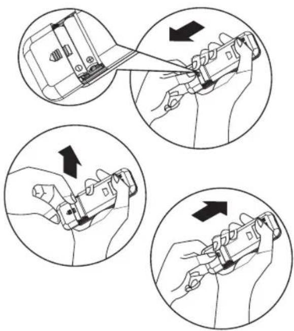
How to insert the batteries
I Insert a pin and gently press down on the battery cover and push in the direction of the arrow to remove, as shown.
2 Insert 2 AAA batteries (1.5V) into the compartment. Ensure that "+" and "-" polarity is correctly positioned.
3 Close the battery cover on the remote control.
How to remove the batteries
Remove the battery cover in the direction of the arrow.
Press the positive pole of the battery softly with your fingers, then draw the batteries out of the compartment. All this should be done by adults, children are forbidden to remove the batteries from the remote control in order to avoid danger of swallow.
Disposal of the batteries
To protect natural resources and to promote material reuse, please separate batteries from other types of waste and recycle them through your local, free battery return system.
Precautions
- When replacing the batteries, do not use new batteries with old batteries, or different types of batteries as this may cause the remote control to malfunction.
- If you do not expect to use the remote control for some time, take the batteries out to prevent leakage of battery acid in the remote control.
- Operate the remote control within effective range. Keep the remote control at least 1 meter from any TV set or HI-FI equipment.
- If the remote control does not work normally, take the batteries out and reinstall after 30 seconds. If it still does not work install new batteries.
• To operate the appliance by remote control, point the remote control at the receiving device on the indoor unit, to ensure receiving sensibility.
• To send a message from remote control, the symbol will flash for 1 second. On receipt of the message, the appliance will emit a beep. - The remote control will operate the air conditioner at a distance of up to 7m.
• Each time the batteries are replaced in the remote control, the remote control is pre-set at Heat mode.
natural_image
Illustration of four hand tools in a mechanical assembly, showing step-by-step disassembly or tool insertion (no text or symbols present)
OPERATING MODE DESCRIPTION
Operating modes:
I. Press and release MODE until you see the symbol glow for the desired setting

- Choose Cooling, Dry, Fan Only or Heating.
- Cooling-Cools the room. Press FAN to select High, Mid or Low. Press the Plus or Minus button to adjust the temperature.
COOL
- Dry-Dries the room. The air conditioner automatically selects the temperature. The fan runs on Low speed only.
NOTE: Dry mode should not be used to cool the room.
DRY
- Fan Only-Only the fan runs. Press FAN to select High, Mid or Low.
FAN
- Heating-Heats the room. Press FAN to select High, Mid or Low. Press the PLUS or MINUS button to adjust the temperature.
NOTE: Heating is NOT available for cooling only air conditioner.
HEAT
Fan Speed
I. Press and release FAN to choose the desired fan speed.

FAN
- Choose High, Mid or Low.
I. When the Filter Reset indicator light is lit, remove, clean and replace the air filter. See "Cleaning the Air Filter."
2. Press and release FILTER button after replacing the air filter.

NOTE: After 360 hours of fan operating time, the Filter indicator light will turn on. It will remain on for 180 hours or until you press FILTER button. After 180 hours, it will turn off automatically.
Temperature
- Press the PLUS button to raise the temperature. Press the PLUS button once to increase the set temperature by 1^ .

- Press the down Adjust button to lower the temperature. Press the down Adjust button once to decrease the set temperature by 1°C, or press twice to decrease the set temperature by 2°C.

NOTES:
- In the Cooling and Heating mode, the temperature can be set between 18^ and 32^ .
- In Fan Only mode, the temperature cannot be set.
- In Dry mode, press the PLUS/MINUS botton the set temperature change by 2^ .
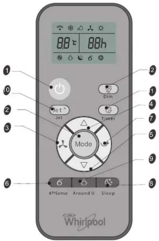
REMOTE CONTROL FUNCTIONS AND INDICATORS
I. ON/OFF BUTTON
Starts and/or Stops the appliance by pressing this button.
2. MODE BUTTON
Used to select the operation mode.
3. FAN BUTTON
Used to select fan speed in sequence auto, high, medium or low.
Used to select the room temperature. Used to set time in timer mode and real time clock.
6. 6TH SENSE BUTTON
Sets or cancels 6th sense operation.
7. SWING BUTTON
Stops or starts horizontal adjustment louver swinging and sets the desired up/down airflow direction.
8. SLEEP BUTTON
Sets or cancels Sleep Mode operation.
9. AROUND U BUTTON
Used to set or cancel Around U function.
10. JET BUTTON
Used to start or stop the fast cooling or heating.
II. TIMER BUTTON
Used to set or cancel the timer on operation. Used to set or cancel the timer off operation.
12. DIM BUTTON
Used to turn on or turn off display light on indoor unit.
INDICATOR SYMBOLS ON RC DISPLAY

Cooling indicator

Dry indicator

Fan only indicator

Heating indicator

Auto fan speed

High fan speed

Medium fan speed

Low fan speed

6th Sense indicator

Sleep indicator

Around U indicator

Jet indicator

Signal transmission

Display set timer

Display set temperature
FUNCTION DESCRIPTIONS
Power On or Off
Press ON/OFF button to turn on or off the unit.

NOTE:
- Changing the mode during operation.
Sometimes the unit does not response at once, wait 3 minutes - Wait 3 minutes before restarting the appliance.
Selecting mode
I. Press and release MODE until you see the symbol glow for the desired setting.

- Choose Cooling, Dry, Fan Only or Heating.
- Cooling-Cools the room. Press Fan to select Auto, High, Mid or Low. Press the up or down Adjust button to adjust the temperature.

- Dry-Dries the room. The air conditioner automatically selects the temperature. Fan runs on Low speed only.
NOTE: Dry mode should not be used to cool the room.
At "Dry" mode, the unit can decrease or rise 2^(3^ or 4^) if you still feel uncomfortable.

- Fan Only-Only the fan runs. Press FAN to select High, Mid or Low.

NOTE: Auto fan speed cannot be selected in Fan Only mode.
- Heating- Heaters the room. Press FAN to select the fan speed. Press the up or down button to select the temperature.

6th Sense mode
The air conditioner automatically selects Cooling or Dry mode, depending on room temperature and sets the target temperature.

Operation mode and temperature are determined by indoor temperature.
| Indoor temperature | Operation mode | Target temperature |
| 21°C or below | HEATING 22°C | |
| 21°C-23°C FAN ONLY | ||
| 23°C-26°C DRY | Room temperature decrease 2°C after operating for 3 minutes | |
| Over 26°C COOLING 26°C | ||
Electric Heat models
| Indoor temperature | Operation mode | Target temperature |
| 21°C or below | FAN ONLY | |
| 23°C-26°C DRY | Room temperature decrease 2°C after operating for 3 minutes | |
| Over 26°C COOLING 26°C | ||
Cooling only models
NOTE: Temperature, airflow and direction are controlled automatically in 6th Sense mode.
However, a decrease or rise of up to 2^ C can be set with the remote control if you still feel uncomfortable.
I. Press 6th Sense button.

6^th Sense
- In Fan Only mode, press Fan to select High, Mid or Low.
Jet mode
Jet button is used for fast cooling or heating.
NOTE: 6th Sense mode button does not operate when Jet function is selected.
I. Press Jet in cooling mode. The air conditioner automatically sets the fan speed and the temperature to 18^ C. Fast heating operates at auto fan speed, changing the set temperature to 32^ C.

- To exit Jet mode press any button except Timer Around U and Swing button.
Fan Speed
I. Choose desired fan speed.
- Each time the "FAN" button is pressed, the fan speed is changed in sequence:
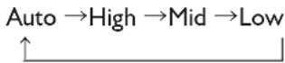
- Auto-automatically controls fan speed depending on current room temperature and temperature control setting.
NOTE: Auto fan speed cannot be selected in Fan Only mode.

• High - for maximum cooling

- Mid - for normal cooling

- Low - for minimum cooling

Temperature
- Press the UP adjust button to raise the temperature. Press the UP Adjust button once to increase the set temperature by 1^ , or press twice to increase the set temperature by 2^ .
- Press the DOWN adjust button to lower the temperature. Press the DOWN adjust bottom to decrease the set temperature by 1°C, or press twice to decrease the set temperature by 2°C.
NOTES:
- In the Cooling or Heating mode, the temperature can be set between 18°C and 32°C.
- In Fan Only mode, the temperature cannot be set.
- In Dry mode, press the UP/DOWN botton the set temperature change by 2^ .
Around U function

When you press this button, the remote control transmits signal of the actual room temperature around it to the unit, and the appliance will operate according to this temperature to let you feel more comfortable.
Please keep the remote control in a location where it can transmit the signal to the unit properly. Press once to set and press again to cancel.
Sleep mode
Press Sleep button on remote control and the indicator in LCD lights up, the appliance operates in sleep mode and the fan speed is automatically set to low speed.

NOTES:
- The appliance will stop operation automatically after operating for 8 hours.
- Fan speed is automatically set at low speed..
- In Cooling mode if the current room temperature is below 26°C, the temperature will automatically increase 1°C during the first hour after Sleep control is activated, then remain the same.
- In Heating mode, the setting temperature will decrease by 3^ at most for 3 hours constantly, then keeps steady.
I. Press MODE to select Cooling, Dry or Heating.
NOTE: Sleep mode cannot be selected when Fan Only is selected.
2. Press the or button to set the temperature.
3. Press SLEEP. After 10 seconds, the lights on the control panel display will dim.
NOTE: The temperature and airflow direction may be adjusted during Sleep control. The fan speed is automatically set to Low speed. After 10 seconds, the lights on the control panel display will dim again.
- To turn off Sleep control, press SLEEP, MODE, FAN, ON/OFF or wait 8 hours for Sleep control to turn off automatically.
DIM function
Press the DIM button to turn off the light and the display in the unit.

NOTES: When the light is off, receive signal will turn on the light again.
TIMER function
It's convenient to set the timer on with TIMER button before you leave so that you will come back to the comfortable room temperature you set. Press the TIMER button to set a switch-on button when the appliance is off. Press the TIMER button to set a switch-off timer during operation.

How to set TIMER
I. Set desired operating mode, temperature setting and fan speed firstly, then press the TIMER button and "01h" flashed on LCD.
2. Set desired operating mode, temperature setting and fan speed firstly, then press the TIMER button and "01h" flashed on LCD.
3. Point the remote control at the signal receptor of the unit, press the + or - button when "01h" flashes.
Choose the timer you want, then press the TIMER button.
- A "beep" can be heard.
- Timer indicator on the control panel lights up.
-
"h" stops flashing.
-
To cancel the set timer: press the TIMER button again, a "beep" can be heard.
NOTES:
- The range can be set is 1 hour to 10 hours.
• After setting a switch-on timer when the appliance is off, the Timer light on the control panel lights and - Setting a switch-off timer when the unit working, the Timer light of the control panel lights up.
Changing Air Direction
Press SWING once to change vertical airflow direction. Press again to stop airflow louver at desired airflow direction.
Normal Sounds
When your air conditioner is operating normally, you may hear sounds such as:
• Air movement from the fan.
- Clicks from the thermostat cycle.
- Vibrations or noise due to poor wall or window construction.
- A high-pitched hum or pulsating noise caused by the modern high-efficiency compressor cycling on and off.
MAINTENANCE
Draining the Air Conditioner
(in accordance with the indication of Water Full under "Starting your local air conditioner".)
I. Press ON/OFF to turn off the air conditioner.
2. Unplug air conditioner or disconnect power.
3. Move the appliance gently and stably to a draining location or outside to drain water. Do not move the unit before water is drained out completely.
4. Remove the secondary drain plug and drain water completely.
5. Remove the primary drain hose from the drain hose clip. Remove the drain hose plug from the end of the primary drain hose and drain water completely.
NOTE: If air conditioner will be stored after use, see "Storing After Use."
- Reinstall the drain hose plug and the secondary drain plug.
- Reattach the primary drain hose to the drain hose clip.
- Reposition the air conditioner.
- Plug in air conditioner or reconnect power.
- Press ON/OFF to start the air conditioner.
Cleaning the Air Filter
I. Press ON/OFF to turn off the air conditioner.
2. Open the filter panel door on the back of the air conditioner and remove it.
3. Remove the air filter from the filter panel door.
4. Use a vacuum cleaner to clean the filter. If filter is very dirty, wash filter in warm water with a mild detergent.
NOTE: Do not wash filter in the dishwasher or use any chemical cleaners.
- Air dry filter completely before replacing to ensure maximum efficiency.
- Reattach the air filter to the filter panel door.
- Reinstall filter panel door.
- Press ON/OFF to start the air conditioner.
Cleaning the Outside
- Unplug air conditioner or disconnect from power.
- Remove the air filter and clean separately. See "Cleaning the Air Filter."
- Wipe outside of the air conditioner with a soft, damp cloth.
- Plug in air conditioner or reconnect power.
- Press ON/OFF to start the air conditioner.
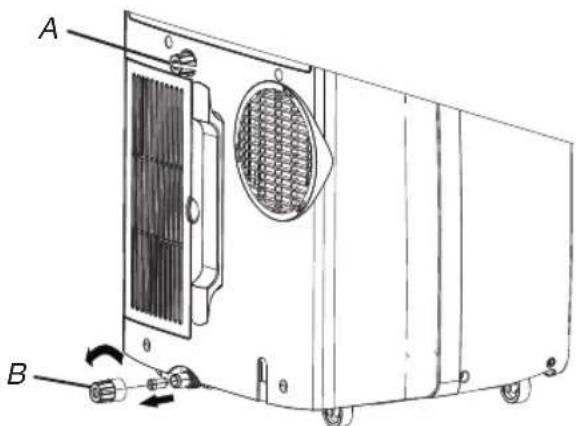
A. Secondary drain plug
B. Drain hose plug
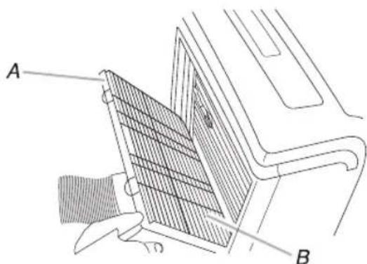
A. Filter panel door
B. Air filter
Storing After Use
I. Drain the water (see the "Draining the Air Conditioner")
2. Run the air conditioner set to Fan Only for approximately 12 hours to dry the air conditioner.
3. Unplug air conditioner.
4. Remove flexible exhaust hose and store with air conditioner in a clean, dry area. See "Installation Instructions."
5. Remove window kit and store with air conditioner in a clean, dry area. See "Installation Instructions."
6. Remove the filter and clean. See "Cleaning the Air Filter."
7. Clean the outside of air conditioner. See "Cleaning the Outside."
8. Reinstall filter.
9. Remove the batteries and store the remote control with air conditioner in a clean, dry area.
TROUBLESHOOTING
Before calling for service, try the suggestions below to see whether you can solve your problem without outside help.
| Trouble Analysis | |
| Air conditioner does not operate | The power supply cord is unplugged. Plug into a grounded outlet. See "Electrical Requirements."A household fuse has blown, or a circuit breaker has tripped. Replace the fuse, or reset the circuit breaker. See "Electrical Requirements."The On/Off button has not been pressed. Press ON/OFF.The local power has failed. Wait for power to be restored.Time-delay fuse or circuit breaker of the wrong capacity is being used. Replace with a time-delay fuse or circuit breaker of the correct capacity. See "Electrical Requirements." |
| Air conditioner blows fuses or trips circuit breakers | Too many appliances are being used on the same circuit. Unplug or relocate appliances that share the same circuit.You are trying to restart the air conditioner too soon after turning off air conditioner. Wait at least 3 minutes after turning off air conditioner before trying to restart it.You have changed modes. Wait at least 3 minutes after turning off air conditioner before trying to restart the appliance. |
| Air conditioner seems to run too much | Is there a door or window open? Keep doors and windows closed.In cooling mode: the air conditioner is in a heavily occupied room, or heat producing appliances are in use in the room. Use exhaust vent fans while cooking or bathing and try not to use heat producing appliances during the hottest part of the day. Local air conditioners are designed as supplemental cooling to local areas within a room. A higher capacity air conditioner may be required, depending on the size of the room being cooled.In heating mode: the air conditioner is in a very cool room. Local air conditioners are designed as supplemental heating to local areas within a room. A higher capacity air conditioner may be required, depending on the size of the room being heated up. |
| Air conditioner runs for a short time only, but room is not cool or hot | Set temperature is close to room temperature. Lower or Higher set temperature. See "Operating mode description". |
| Display error code | If the unit display error code E5, it is water full in the unit, you should drain the water, see "Draining the air conditioner". After draining, you can operate the unit.If the unit display error code E1/E2/E3/E6/E7/EA, please contact customer service. |
| Air conditioner runs, but does not cool/hot | The filter is dirty or obstructed by debris. Clean the filter.Air outlet is blocked. Clear air outlet.The setting temperature is not compatible. In cooling mode: set temperature is too high. Lower set temperature. In heating mode: set temperature is too low. Higher set temperature. |
| Air conditioner cycles on and off too much | The air conditioner is not properly sized for your room. Check the cooling/heating capabilities of your local air conditioner. Local air conditioners are designed as supplemental cooling/heating to local areas within a room.The filter is dirty or obstructed by debris. Clean the filter.In cooling mode there is excessive heat or moisture (open container cooking, showers, etc.) in the room. Use a fan to exhaust heat or moisture from the room. Try not to use heat-producing appliances during the hottest part of the day. In heating mode the temperature of the environment is too high. Do not use your air conditioner when the temperature of the environment is too high.The louvers are blocked. Install the air conditioner in a location where the louvers are free from curtains, blinds, furniture, etc.The outside temperature is below 18°C. Do not try to operate your air conditioner in the cooling mode when the outside temperature is below 18°C. |
INSTALLATION REQUIREMENTS
Tools and Parts
Gather the required tools and parts before starting installation. Read and follow the instructions provided with any tools listed here.
I. Tools needed
• Phillips screwdriver
- Saw
• Cordless drill and 1/8" bit
- Scissors
- Pencil
- Parts Supplied
The company provides only one plan to install local air conditioner. See "Install local Air Conditioner".
natural_image
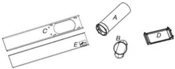
Technical line drawings of battery components including a cylindrical tube, rectangular plates, and a ring (no text or symbols)A. Flexible exhaust hose
B. Window exhaust adapter
C. Outer slider section
D. Rain Cover
E. Inner slider section
Location Requirements
NOTES:
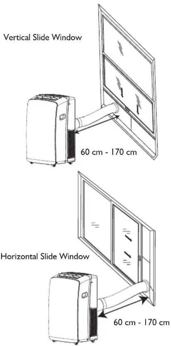
- The flexible exhaust hose allows placement of the air conditioner between 23 12 and 67" (60 cm and 170 cm) from window or door.
- Local air conditioners are designed as supplemental cooling to local areas within a room.
- To ensure proper ventilation, keep the required distance from the return air outlet to the wall or other obstacles at least 23^1/2 (60 cm).
- Do not block air outlet.
- Provide easy access to grounded outlet.
Electrical Requirements
- The local air conditioner should be connected to a 220-240V / 50Hz, 20-amp fused grounded outlet.
- The use of a time-delay fuse or time-delay circuit breaker is recommended.
- All wiring must comply with local and national electrical regulations and be installed by a qualified electrician. If you have any questions, contact a qualified electrician.
Use your power supply cord:
Plug power supply cord into a grounded outlet.
NOTES:
- A damaged power supply cord must be replaced with a new power supply cord obtained from the product manufacturer and must not be repaired.
INSTALLATION INSTRUCTIONS
Unpack the Air Conditioner
Remove packaging materials
- Remove and dispose of/recycle packaging materials. Remove tape and glue residue from surfaces before turning on the air conditioner. Rub a small amount of liquid dish soap over the adhesive with your fingers. Wipe with warm water and dry.
- Do not use sharp instruments, rubbing alcohol, flammable fluids, or abrasive cleaners to remove tape or glue. These products can damage the surface of your air conditioner.
Install Local Air Conditioner
Install Exhaust Hose and Adapter
I. Open the window.
2. Measure the window opening.
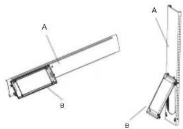
- If the window opening is too narrow for the window slider kit, remove the inner slider from the window slider kit.

A. Inner slider section
B. Outer slider section
• Using a saw, cut the inner slider section to fit the window opening.
- Slide the inner slider section into the outer slider section of the window slider kit.
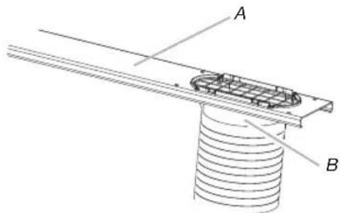
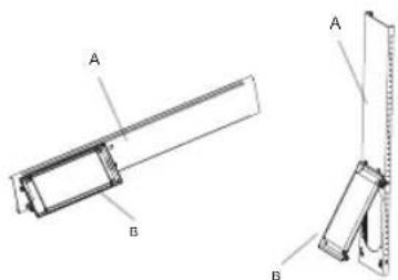
3. Place the window slider kit into the window, extending it to fit the width of the window. Be sure the rain cover is on the outside of the window.

natural_image
Diagram showing two views of a storage or ventilation system with arrows indicating direction (no text or symbols)NOTE: For casement window installation, the window slider kit may be installed vertically with the window slider kit opening at the bottom.

natural_image
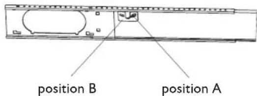
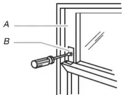
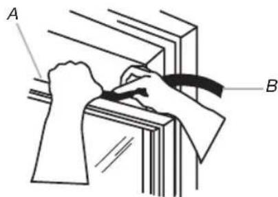
Diagram showing two door frame structures with directional arrows indicating movement or force (no text or symbols)- Use a special plastic device with spring to fix the window brackets: Place the device to the position A, the pin may stretch out then lock the brackets, when place the device to position B, the pin will draw back and the brackets will be released the window slider kit.
- Close the window onto the window slider kit to secure.
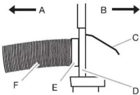
A To local air conditioner
B Outdoors
C Rain cover
D Window slider kit
E Window exhaust adapter
F Flexible exhaust hose
Install Exhaust Hose and Adapter
-
Roll the air conditioner to selected location. See "location Requirements".
-
Attach the window exhaust adapter to the flexible exhaust hose. Turn anticlockwise until securely locked into place.
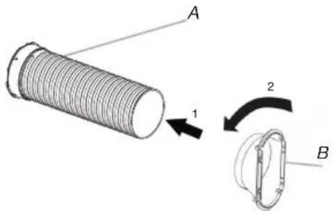
A Flexible exhaust hose
B Window exhaust adapter
-
Insert the dummy coupling into the slot on the back of the air conditioner.
-
Put and rotate to lock the hose into place.
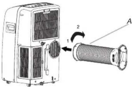
A. Flexible exhaust hose
Window Installation
-
Your window slider kit has been designed to fit most standard vertical and horizontal window applications. Roll the air conditioner to selected location. See "Location Requirements".
-
Insert the window exhaust adapter into the slot on the window slider kit.
A. Window slider kit
B. Window exhaust adapter
Rain Cover Installation
Attach the rain cover to the holes of the outer slider section. Then slide the rain cover until securely locked place.
Vertical Installation
Horizontal Installation
A. Out slider section
B. Rain cover
Complete Installation
-
Place the window-lock bracket on top of the lower window and against the upper window sash.
-
Use 1/8" drill bit to drill a starter hole through the hole in the bracket.
-
Attach the window-lock bracket to the window sash with wood screw(provdie 4) to secure the window in place.
A. Upper window sash
B. Window-lock bracket
- Insert the foam seal behind the top of the lower window sash and against the glass of the upper window.
A. Top of lower window sash
B. Foam seal
AFTER SALES SERVICE
Before contacting the Customer Care Centre:
- Try to solve the problem yourself based on the descriptions given in the "Troubleshooting".
- Turn the appliance off and restart it to see if the fault persists.
If after carrying out the above checks, the fault persists, contact the Customer Care Centre.
Please give:
- a short description of the fault;
• the exact model of the air conditioner; - the service number (this is the number found after the word Service on the rating plate), located on the back of the appliance. The service number can also be found in the warranty booklet;
- your full address;
- your telephone number.
If repair work has to be carried out, contact the Customer Care Centre (Use of original spare parts and a proper repair is guaranteed).
You will need to present the original invoice.
Failure to comply with these instructions could compromise the safety and quality of your product.
SERVICE
0000 000 00000
AVANT D'UTILISER L'APPAREIL
natural_image
Technical line drawings of battery components including a cylindrical tube, rectangular plates, and a ring (no text or symbols)natural_image
Diagram showing two views of a storage or ventilation system with arrows indicating direction (no text or symbols)natural_image
Diagram showing two door frame arrangements with directional arrows indicating movement (no text or symbols)natural_image
Technical line drawing of a mechanical assembly with labeled components A and B (no text or symbols present)AFVOER VAN DE VERPAKKING
AFVOER VAN HET APPARAAT
natural_image
Technical line drawings of battery components including a cylindrical tube, rectangular plates, and a ring (no text or symbols)natural_image
Diagram showing two views of a storage or ventilation system with arrows indicating direction (no text or symbols)natural_image
Diagram showing two views of a door with directional arrows indicating movement or force (no text or symbols)natural_image
Illustration of four hand tools in a mechanical assembly, showing step-by-step disassembly or tool insertion (no text or symbols present)
12. BOTÓN DIM (penumbra)
natural_image
Technical line drawings of battery components including a cylindrical tube, rectangular plates, and a ring (no text or symbols)natural_image
Diagram showing two views of a storage or storage unit with arrows indicating movement, no text or symbols present.natural_image
Diagram showing two views of a door with directional arrows indicating movement or force (no text or symbols)natural_image
Technical line drawings of battery components including a cylindrical tube, rectangular plates, and a ring (no text or symbols)natural_image
Diagram showing two views of a storage or storage unit with arrows indicating direction (no text or symbols)natural_image
Diagram showing two views of a door frame with arrows indicating direction (no text or symbols)A. Mangueira de descarga
natural_image
Technical line drawings of battery components including a cylindrical tube, two rectangular plates, and a multi-pin connector (no text or symbols)natural_image
Diagram showing two views of a storage or ventilation system with arrows indicating direction (no text or symbols)natural_image
Diagram showing two door frame configurations with directional arrows indicating movement (no text or symbols)8. KOYMΠI SLEEP (Υπνος)
natural_image
Technical line drawings of cylindrical and rectangular components (no text or symbols)natural_image
Diagram showing two views of a storage or storage unit with arrows indicating direction (no text or symbols)natural_image
Diagram showing two door frame structures with directional arrows indicating movement or force (no text or symbols)natural_image
Illustration of four hand tools in a mechanical assembly, showing step-by-step disassembly or tool insertion (no text or symbols present)
BESKRIVNING AV FUNKTIONSLÄGEN
Funktionslägen:
6. KNAPPEN 6TH SENSE (6:E SINNE)
12. KNAPPEN DIM (DÄMPA LJUS)
natural_image
Technical line drawings of battery components including a cylindrical tube, rectangular plates, and a segmented ring (no text or symbols)natural_image
Diagram showing two views of a storage or ventilation system with arrows indicating direction (no text or symbols present)natural_image
Diagram showing two views of a door with directional arrows indicating movement or force (no text or symbols)A. Flexibel utsugsslang
Fönsterinstallation
Vertical installation
Horisontell installation
FORHOLDSREGLER FOR KLIMAANLEGGET

BESKRIVELSE AV DRIFTSMODUS
Driftsmoduser:
Vis timer-innstilling

Vis innstilt temperatur
FUNKSJONSBESKRIVELSER
Strøm av eller på
natural_image
Technical line drawings of battery components including a cylindrical tube, rectangular plates, and a segmented ring (no text or symbols)A. Innvendig gliderdel
B.Ytre gliderdel
natural_image
Diagram showing two views of a storage or ventilation system with arrows indicating flow direction (no text or symbols)natural_image
Diagram showing two views of a door with directional arrows indicating movement or force (no text or symbols)A. Ytre gliderdel
B. Regndeksel

BESKRIVELSE AF FUNKTIONSMETODEN
Funktionsmetoder:
12. KNAPPEN DÆMPNING
Indikator for 6th Sense

Indikator for Slumre

Indikator for Around U

Indikator for Jet

Signaltransmission

Vis indstillet timer

Vis indstillet temperatur
FUNKTIONSBESKRIVELSER
On eller Off
natural_image
Technical line drawings of battery components including a cylindrical tube, rectangular plates, and a segmented ring (no text or symbols)A. Indre skydersektion
B.Ydre skydersektion
natural_image
Diagram showing two views of a storage or ventilation system with arrows indicating direction (no text or symbols)natural_image
Diagram showing two views of a door with directional arrows indicating movement or force (no text or symbols)
KAUKOSÄÄTIMEN TOIMINNOT JA KUVAKKEET
I. VIRTAPAINIKE
6. 6TH SENSE -PAINIKE
natural_image
Technical line drawings of battery components including a cylindrical tube, rectangular plates, and a segmented ring (no text or symbols)A. Joustava poistoletku
B. Ikkunan poistoaukon sovitin
C. Ulompi liukuosa
D. Sadesuoja
E. Sisempi liukuosa
Paikan vaatimukset
HUOMAUTUKSIA:
A.Sisempi liukuosa
B.Ulompi liukuosa
natural_image
Diagram showing two views of a storage or ventilation system with arrows indicating direction (no text or symbols)natural_image
Diagram showing two views of a door with directional arrows indicating movement or force (no text or symbols)A. Ulompi liukuosa
B. Sadesuoja

natural_image
Technical line drawings of cylindrical and rectangular components labeled A, B, C, D, E (no text or symbols beyond labels)natural_image
Diagram showing two views of a storage or ventilation system with arrows indicating direction (no text or symbols)natural_image
Diagram showing two door frame configurations with directional arrows indicating movement or flow (no text or symbols)A. Suwak zewnętrzny
natural_image
Illustration of three hand tool manipulation steps showing tool positioning and adjustment (no text or symbols)
POŽADAVKY K INSTALACI
Nářadí a díly
natural_image
Technical line drawings of cylindrical and rectangular components labeled A, B, C, D, E (no text or symbols beyond labels)natural_image
Diagram showing two views of a storage or ventilation system with arrows indicating direction (no text or symbols)natural_image
Diagram showing two views of a door frame with directional arrows indicating movement (no text or symbols)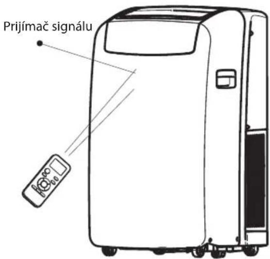
4-5. TLAČIDLO TEPLOTY
12. TLAČIDLO DIM (Tlmenie)
natural_image
Technical line drawings of cylindrical and rectangular components labeled A, B, C, D, E (no text or symbols beyond labels)POKYNY NA INŠTALÁCIU
natural_image
Diagram showing two views of a storage or ventilation system with arrows indicating direction (no text or symbols)natural_image
Diagram showing two door frame arrangements with directional arrows indicating movement (no text or symbols)
ÜZEMMÓD LEÍRÁSA
Üzemmódok:
12. DIM (HALVÁNY) GOMB
natural_image
Technical line drawings of cylindrical and rectangular components (no text or symbols)A.Belső csúszórész
B. Külső csúszórész
natural_image
Diagram showing two views of a storage or ventilation system with arrows indicating direction (no text or symbols)natural_image
Diagram showing two door frame configurations with directional arrows indicating movement (no text or symbols)A. Külső csúszórész
B. Fedölemez
natural_image
Illustration of four hand tools in a manual setting, showing progressive disassembly or assembly (no text or symbols present)
natural_image
Technical line drawings of cylindrical and rectangular components (no text or symbols)natural_image
Diagram showing two views of a storage or ventilation system with arrows indicating direction (no text or symbols)natural_image
Diagram showing two door frame structures with directional arrows indicating movement or force (no text or symbols)natural_image
Illustration of three hand tools in a mechanical assembly, showing step-by-step disassembly or tool manipulation (no text or symbols present)natural_image
Technical line drawings of cylindrical and rectangular components labeled A, B, C, D, E (no text or symbols beyond labels)A. Вътрешен плъзгач
В. Външен плъзгач
natural_image
Diagram showing two views of a storage or ventilation system with arrows indicating direction (no text or symbols)natural_image
Diagram showing two door frame configurations with directional arrows indicating movement or force (no text or symbols)A. Външен плъзгач
В. Капак срещу дъжд
Пълен монтаж
natural_image
Illustration of four hand tools in a mechanical assembly, showing step-by-step disassembly or tool insertion (no text or symbols present)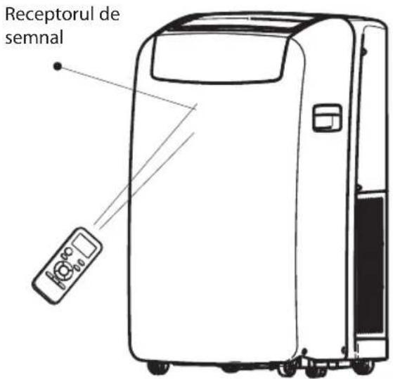
DESCRIEREA MODULUI DE FUNCTIONARE
Moduri de functionare:
6. BUTONUL AL 6-LEA SIMT
12. BUTONUL ATENUARE
natural_image
Technical line drawings of battery components including a cylindrical tube, rectangular plates, and a ring (no text or symbols)natural_image
Diagram showing two views of a storage or storage unit with arrows indicating flow direction (no text or symbols)natural_image
Diagram showing two views of a door with directional arrows indicating movement or force (no text or symbols present)A. Furtun flexibil de evacuare

- Brugsanvisning
- Οδηγίες χρήσης
- Návod k použití
- TASTE 6TH SENSE (6. SINN)
- SAFETY PRECAUTIONS
- AIR CONDITIONER PRECAUTIONS
- Please strictly follow the below instructions:
- SAFEGUARDING THE ENVIRONMENT
- SCRAPPING OF PACKAGING
- SCRAPPING OF APPLIANCE
- STARTING YOUR LOCAL AIR CONDITIONER
- IMPORTANT:
- STORAGE AND TIPS FOR USING THE RC
- How to insert the batteries
- How to remove the batteries
- Disposal of the batteries
- Precautions
- OPERATING MODE DESCRIPTION
- Operating modes:
- Fan Speed
- Temperature
- NOTES:
- REMOTE CONTROL FUNCTIONS AND INDICATORS
- ON/OFF BUTTON
- MODE BUTTON
- FAN BUTTON
- 6TH SENSE BUTTON
- SWING BUTTON
- SLEEP BUTTON
- AROUND U BUTTON
- JET BUTTON
- TIMER BUTTON
- DIM BUTTON
- INDICATOR SYMBOLS ON RC DISPLAY
- FUNCTION DESCRIPTIONS
- Power On or Off
- NOTE:
- Selecting mode
- 6th Sense mode
- Cooling only models
- Jet mode
- Around U function
- Sleep mode
- DIM function
- TIMER function
- How to set TIMER
- Changing Air Direction
- Normal Sounds
- MAINTENANCE
- Draining the Air Conditioner
- Cleaning the Air Filter
- Cleaning the Outside
- Storing After Use
- TROUBLESHOOTING
- INSTALLATION REQUIREMENTS
- Tools and Parts
- Location Requirements
- Electrical Requirements
- Use your power supply cord:
- INSTALLATION INSTRUCTIONS
- Unpack the Air Conditioner
- Install Local Air Conditioner
- Install Exhaust Hose and Adapter
- Window Installation
- Rain Cover Installation
- Complete Installation
- AFTER SALES SERVICE
- Before contacting the Customer Care Centre:
- If after carrying out the above checks, the fault persists, contact the Customer Care Centre.
- AVANT D'UTILISER L'APPAREIL
- AFVOER VAN DE VERPAKKING
- AFVOER VAN HET APPARAAT
- BOTÓN DIM (penumbra)
- KOYMΠI SLEEP (Υπνος)
- BESKRIVNING AV FUNKTIONSLÄGEN
- Funktionslägen:
- KNAPPEN 6TH SENSE (6:E SINNE)
- KNAPPEN DIM (DÄMPA LJUS)
- Fönsterinstallation
- FORHOLDSREGLER FOR KLIMAANLEGGET
- BESKRIVELSE AV DRIFTSMODUS
- Driftsmoduser:
- FUNKSJONSBESKRIVELSER
- Strøm av eller på
- BESKRIVELSE AF FUNKTIONSMETODEN
- Funktionsmetoder:
- KNAPPEN DÆMPNING
- FUNKTIONSBESKRIVELSER
- On eller Off
- KAUKOSÄÄTIMEN TOIMINNOT JA KUVAKKEET
- VIRTAPAINIKE
- 6TH SENSE -PAINIKE
- Paikan vaatimukset
- HUOMAUTUKSIA:
- POŽADAVKY K INSTALACI
- Nářadí a díly
- 4-5. TLAČIDLO TEPLOTY
- TLAČIDLO DIM (Tlmenie)
- POKYNY NA INŠTALÁCIU
- ÜZEMMÓD LEÍRÁSA
- Üzemmódok:
- DIM (HALVÁNY) GOMB
- Пълен монтаж
- DESCRIEREA MODULUI DE FUNCTIONARE
- Moduri de functionare:
- BUTONUL AL 6-LEA SIMT
- BUTONUL ATENUARE
Brand : WHIRLPOOL
Model : PACB12HP
Category : Air Conditioning