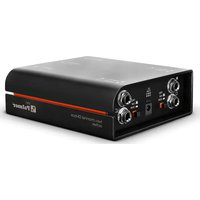
RIVER inn - Audio Equipment Palmer - Free user manual and instructions
Find the device manual for free RIVER inn Palmer in PDF.


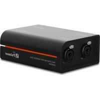
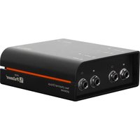
| Product type | 2-channel active direct box |
| Number of channels | 2 |
| Inputs | 2 x 6.35 mm jack (unbalanced) |
| Outputs | 2 x male XLR (balanced) + 1 x mono sum XLR |
| THRU outputs | 2 x 6.35 mm jack |
| Attenuation (PAD) | 0 dB / 30 dB per channel |
| Ground Lift | Yes, per channel |
| Power supply | 48 V phantom power or external 9-24 V DC power supply |
| Power consumption | 0.5 W |
| Frequency response | 20 Hz - 20 kHz (±1 dB) |
| Input impedance (PAD 0 dB) | 500 kΩ |
| Output impedance | 110 Ω |
| Max input level (1% THD) | +11 dBu |
| Max output level (1% THD) | +5.5 dBu |
| THD+N (1 kHz, +4 dBu) | < 0.0013 % |
| Signal-to-noise ratio | 108 dB |
| Housing | Extruded aluminum |
| Dimensions (H x W x D) | 140 x 50 x 128 mm |
| Weight | 0.72 kg |
| Operating temperature | -20 °C to 70 °C |
| Included accessories | Rubber feet, identification label, product sheet |
| Maintenance and cleaning | Use a dry, soft cloth. Do not use abrasive products or solvents. |
| Safety instructions | Do not open the device. Use indoors only. Respect the polarity and supply voltage. |
| Repairability | The device contains no user-serviceable parts. Refer all servicing to qualified personnel. |
Frequently Asked Questions - RIVER inn Palmer
User questions about RIVER inn Palmer
0 question about this device. Answer the ones you know or ask your own.
Ask a new question about this device
Download the instructions for your Audio Equipment in PDF format for free! Find your manual RIVER inn - Palmer and take your electronic device back in hand. On this page are published all the documents necessary for the use of your device. RIVER inn by Palmer.
USER MANUAL RIVER inn Palmer
be true to your sound
5
years
guarantee
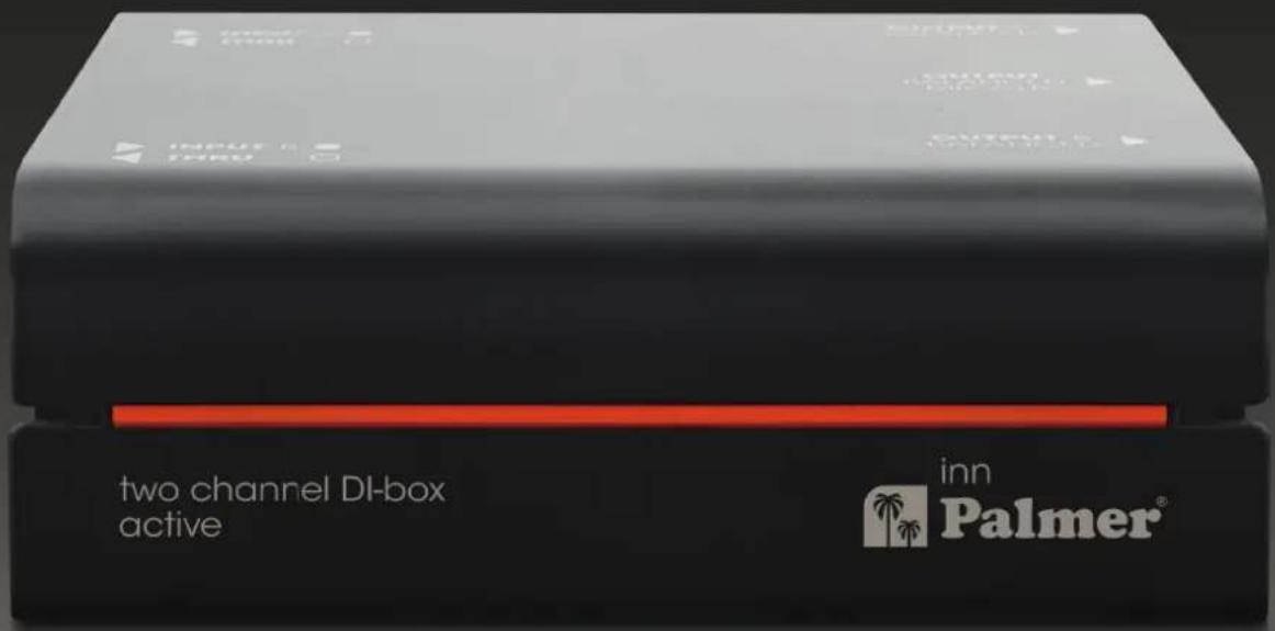
Two channel DI-box active
inn
EN USER MANUAL 3
INFORMATION ON THIS USER MANUAL 4
INTENDED USE 4
EXPLANATIONS OF TERMS AND SYMBOLS 4
SAFETY INSTRUCTIONS 5
NOTES FOR PORTABLE INDOOR DEVICES 7
PACKAGING CONTENT 8
INTRODUCTION 8
CONNECTIONS, OPERATING AND DISPLAY ELEMENTS 9
NOTES 10
CONNECTION EXAMPLES 11
TECHNICAL SPECIFICATIONS 12
SIGNAL FLOW DIAGRAM 13
MANUFACTURER'S DECLARATIONS 14
Let your signals flow, naturally and powerfully like a river! The River Series embodies this claim down to the last detail: highly precise switches designed by our award-winning engineers ensure that sound reaches its destination undistorted – the heart of your listeners.
That's exactly what Palmer® stands for. We have been manufacturing audio tools for professional use on stage, in broadcasting, and in the studio since 1980. Musicians and sound engineers around the world value our solutions developed in Germany for their unhindered signal flow and pure sound – as crystal clear and vibrant as water! So what was more logical than naming the River Series models after German rivers?
On the map of Germany, you can see that the 517 km long Inn river originates from Switzerland and Austria and flows through south-east Bavaria.
Thank you for purchasing the inn! We hope you enjoy this piece of German engineering. Be true to your sound!
Yours, the Palmer Team
inn
Active two-channel DI box
INFORMATION ON THIS USER MANUAL
Carefully read the safety instructions and the entire manual before operating the device.
▶Observe the warnings on the device and in the user manual.
▶Always keep the user manual within reach.
If you sell or pass on the device, it is important that you also include this user manual, as it is an integral part of the product.
INTENDED USE
This product is a device for event technology, as well as for the studio, TV, and broadcasting!
The product has been developed for professional use in event technology, as well as in the studio, TV, and broadcasting.
Furthermore, this product is only intended for qualified users with specialist knowledge of event technology, as well as studio, TV, and broadcasting!
▶ Use of the product outside the specified technical data and operating conditions is considered improper use!
▶ Liability for damage and third-party damage to persons and property due to inappropriate use is excluded!
▶The product is not suitable for:
▶ Use by persons (including children) with limited physical, sensory, or mental abilities or lack of experience and knowledge.
Children (children must be instructed not to play with the device).
DEFINITIONS AND SYMBOL EXPLANATIONS
- DANGER: The word DANGER, possibly in combination with a symbol, indicates immediately hazardous situations or conditions risking life and limb.
- WARNING: The word WARNING, possibly in combination with a symbol, indicates potentially hazardous situations or conditions risking life and limb.
- CAUTION: The word CAUTION, possibly in combination with a symbol, indicates situations or conditions that may lead to injury.
- ATTENTION: The word ATTENTION, possibly in combination with a symbol, indicates situations or conditions that can lead to damage to property and/or the environment.

This symbol indicates hazards that can cause electric shock.

This symbol indicates hazardous areas or hazardous situations.

This symbol indicates hazards caused by hot surfaces.

This symbol indicates hazards due to high volume levels.

This symbol denotes a device that does not contain any user-serviceable parts.

This symbol indicates additional information on the operation of the product.

This symbol indicates a device that may only be used in dry rooms.
SAFETY INSTRUCTIONS

DANGER:
- Do not open the device, and do not make any modifications to it.
- If your device no longer functions properly, if liquids or objects get inside it, or if it has been damaged in any other way, switch it off immediately and disconnect it from the power supply. The device may be repaired only by authorised repair technicians.

ATTENTION:
- Do not operate the device if it has been exposed to large temperature fluctuations (for example, after transport). Moisture and condensation can damage the device. Switch on the device only when it has reached ambient temperature.
- Make sure that the voltage and frequency of the mains correspond to the values specified on the device. If the device has a voltage selector switch, do not turn the device on until it has been set correctly. Use only suitable mains cables.
- To disconnect the device completely from the power supply, unplug the mains cable or the mains adapter from the socket. It is not sufficient to press the on/off switch on the device. In addition, a connected amplifier must also be disconnected from the device!
- Make sure that the fuse used corresponds to the type printed on the device.
- Make sure that appropriate measures have been taken against power surges (for example, lightning strike).
- Observe the specified maximum output current on devices with a Power Out connection. Ensure that the total current consumption of all connected devices does not exceed the specified value.
- Replace plug-in mains cables with original cables only.

DANGER:
- Danger of suffocation/choking! Plastic bags and small parts must be kept out of reach of persons (including children) with reduced physical, sensory, or mental capabilities.
- Danger caused by falling device! Make sure that the device is securely installed and cannot fall down. Only use suitable stands or mounts (particularly for fixed installations). Ensure that accessories are properly installed and secured. Ensure that all applicable safety regulations are observed.

WARNING:
- Use the device in the prescribed manner only.
- Operate the device only with the accessories recommended and intended by the manufacturer.
- During installation, observe the safety regulations applicable in your country.
- After connecting the device, check all cable routes to avoid damage or accidents, for example, due to tripping hazards.
- Always observe the specified minimum distance to normally flammable materials! Unless explicitly stated, the minimum distance is 0.3 m.

CAUTION:
Moving components such as mounting brackets or other movable components may become jammed.

ATTENTION:
- Do not install or use the device in the vicinity of radiators, heat accumulators, furnaces, or other heat sources. Ensure that the device is always installed in such a way that it is sufficiently cooled and cannot overheat.
- Do not place any ignition sources such as burning candles near the device.
- Use the original packaging or packaging provided by the manufacturer for transport.
- Avoid shock or impact to the device.
- Observe the IP protection class as well as the ambient conditions such as temperature and humidity according to the specifications.
- Devices can be continuously further developed. In the event of deviating information on operating conditions, performance, or other device properties between the user manual and the device labelling, the information provided on the device always has priority.
- The device is not suitable for tropical climates and for operation at heights of 2,000 m above sea level.
- Unless explicitly stated, the device is not suitable for operation under marine conditions.

PLEASE NOTE: For conversion or retrofit kits supplied by the manufacturer, the enclosed installation instructions must be observed.

ATTENTION: HIGH-VOLUME AUDIO PRODUCTS!
This device is designed for professional use. The commercial operation of this device is subject to the applicable national regulations and guidelines for accident prevention.
Hearing damage due to high volume and continuous exposure: use of this product may generate high sound pressure levels (SPLs) that may cause hearing damage. Avoid exposure to high volumes.

ATTENTION: Connecting signal cables and operating switches (for example, switching phantom power on and off) can cause significant interference noise. Make sure that input channels (mixer, audio interface, effects device, etc.) are muted while making connections and operating switches. Otherwise, noise levels may cause damage.

WARNING: Unplug the mains adapter from the socket AND disconnect any amplifier that might be connected to the device to put the device in a completely voltage-free state.

ATTENTION: Make sure that the device is not covered while in operation and that the air can freely circulate, especially for the rack mounting!

PLEASE NOTE: Strong magnetic fields can cause humming. For this reason, do not position the device near strong magnetic fields (for example, mains transformer).

PLEASE NOTE FOR PORTABLE INDOOR DEVICES:
- Temporary operation! Event equipment is generally designed for temporary use only.
- Continuous operation or permanent installation can impair the functioning of the device and cause premature ageing.
PACKAGING CONTENT
Remove the product from the packaging and remove all packaging material.
Please check the completeness and integrity of the delivery and notify your distribution partner immediately after purchase if the delivery is not complete or if it is damaged.
The packaging content for the product includes:
▶1x inn active two-channel DI box
▶Product data sheet
▶Tour label
▶Rubber feet
INTRODUCTION
The two-channel DI box inn is a professional studio and stage tool that transforms unbalanced audio signals into balanced audio signals without any distortion. The internal transformer offers an excellent dynamic range and outstanding overload stability. The DI box is used as a connecting link to connect string instruments with pickups (for example, electric acoustic guitars, electric guitars, and electric basses), instruments with line outputs (for example, keyboards), and speaker outputs from guitar amplifiers to balanced inputs of a mixer or audio interface. In addition, the DI box allows for interference-free transmission of audio signals over long cable runs.

WARNING: Power amplifiers may not be operated in Bridge mode on the DI box.

WARNING: If an amplifier is operated on the DI box, the ground connection between the input and output must be disconnected (switch no. 6 in the unpressed LIFT position).

WARNING: A connected amplifier's output must not exceed 120 W at 8 ohms!

ATTENTION: If a tube amplifier is used: there is no load resistor in the DI box circuit! To prevent damage to the amplifier, an appropriate guitar speaker or a suitable load resistor must be connected to the THRU jack socket using a speaker cable before switching on the amplifier!
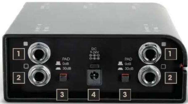
CONNECTIONS AND OPERATING/DISPLAY ELEMENTS - FRONT
Audio input with 6.3 mm jack sockets.
A. Connect an instrument using a shielded instrument cable.
B. Connect the speaker output of a guitar amplifier using a speaker cable (tip: press PAD switch no. 3).
2. THRU A/THRU B
The input signal is output unchanged via the 6.3 mm jack sockets (INPUT A -> THRU A / INPUT B -> THRU B).
3. PAD A/PAD B (passive attenuation device)
Press the corresponding switch to reduce the level of the output signal by 30 dB. The output level must be lowered if the channel input stage of the connected mixer or audio interface is overdriven.
4. DC 9-24 V
Low-voltage socket for connecting an external mains adapter with 9 to 24 V DC voltage and a minimum of 100 mA (both polarity types possible; mains adapter optionally available). As soon as the required voltage is applied to the device, the corresponding indicator LED lights up.
Alternative power supply via 48 V phantom power via at least two OUTPUT XLR sockets. Always make sure that the cable is connected to the audio output and that the channel volume for a connected mixer or audio interface is set to minimum before switching on phantom power. Before disconnecting the cable from the device, turn the channel volume to minimum and then deactivate phantom power.
natural_image
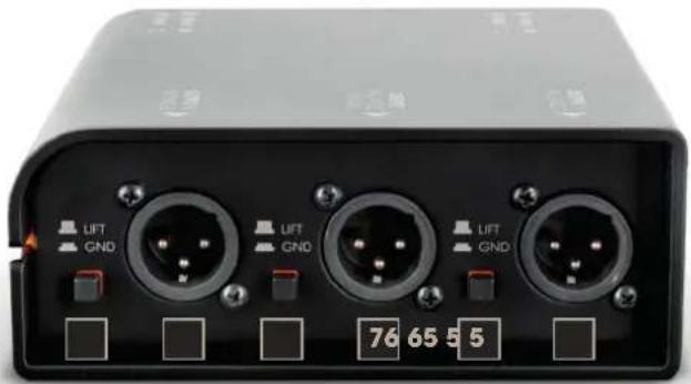
Front panel of a black electronic device with three GND connectors and labeled buttons (no readable text beyond labels)CONNECTIONS AND OPERATING/DISPLAY ELEMENTS - BACK
5. LIFT / GND A - LIFT / GND B - LIFT / GND A+B
Switch for disconnecting the ground connection between the corresponding channel's input and output (ground lift). The ground connection is disconnected in the unpressed position; the connection is established when the switch is pressed. The ability to prevent a humming loop using the ground lift switch depends on the grounding of the connected devices. It is therefore possible that either switch position effectively reduces or eliminates humming.
6. OUTPUT A/OUTPUT B
Balanced audio output with male three-pin XLR sockets. Use a balanced, shielded cable (for example, microphone cable) in order connect the DI box to a mixer's or audio interface's balanced output.
7. OUTPUT A+B
Balanced audio output with male three-pin XLR socket. Channel A and B signals are mono summed here. Use a balanced, shielded cable (for example, microphone cable) in order connect the DI box to a mixer's or audio interface's balanced output.

ATTENTION: Connecting signal cables can cause significant interference noise. Make sure that devices connected to the output channel (mixer, audio interface, etc.) and the THRU output are muted while making connections. Otherwise, noise levels may cause damage.

PLEASE NOTE
The line outputs on the front and rear are galvanically isolated from the line inputs.
If several line outputs are used simultaneously on one channel, the signal level may be slightly reduced.
CONNECTION EXAMPLES
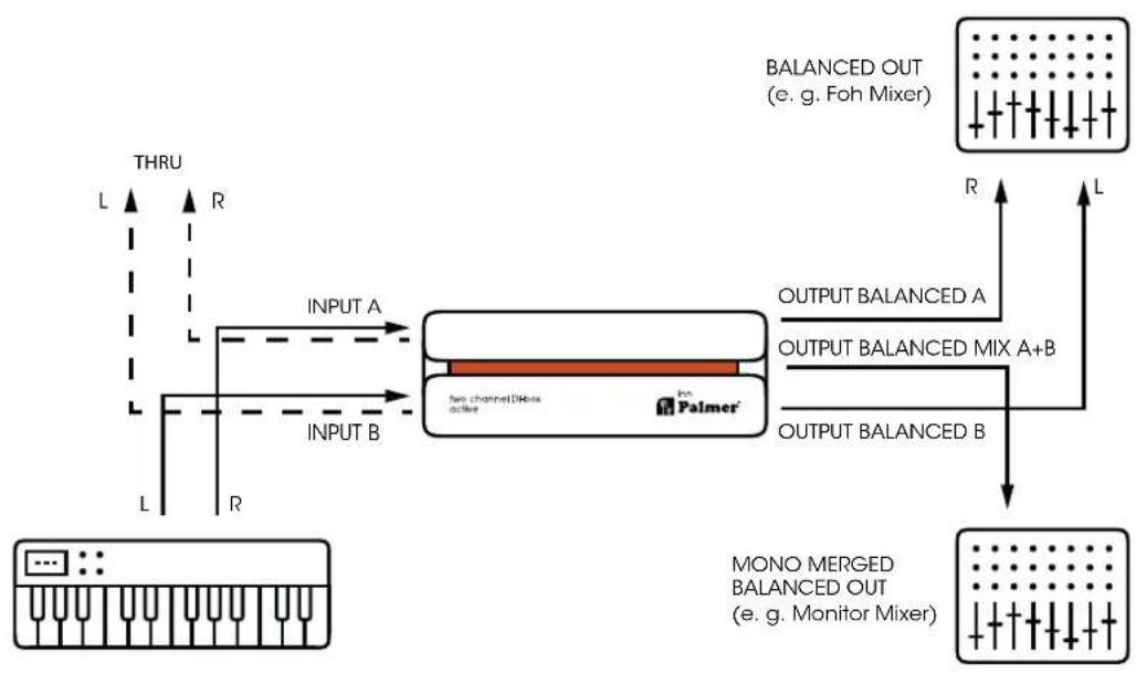
flowchart
graph TD
    A["THRU"] --> B["INPUT A"]
    B --> C["Two channel DBox active"]
    C --> D["BALANCED OUT (e.g. Foh Mixer)"]
    D --> E["OUTPUT BALANCED A"]
    E --> F["Output BALANCED MIX A+B"]
    F --> G["OUTPUT BALANCED B"]
    G --> H["MONO MERGED BALANCED OUT (e.g. Monitor Mixer)"]
    H --> I["R"]
    I --> J["L"]
    K["L"] --> L["THRU"]
    M["R"] --> N["THRU"]
    O["L"] --> P["THRU"]
    Q["L"] --> R["THRU"]
    S["R"] --> T["THRU"]
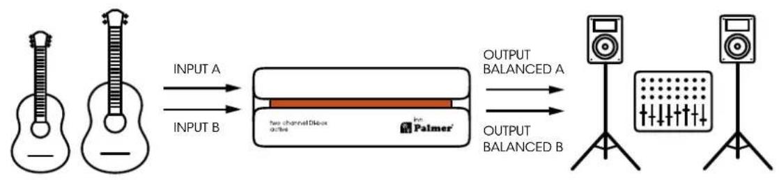
flowchart
graph LR
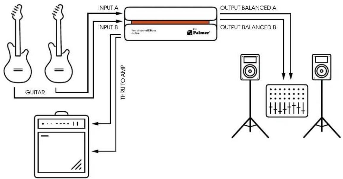
    A["Input: guitar"] -->|INPUT A| B["Two-channel microphone"]
    C["Input: guitar"] -->|INPUT B| B
    B --> D["Output: balanced A"]
    B --> E["Output: balanced B"]
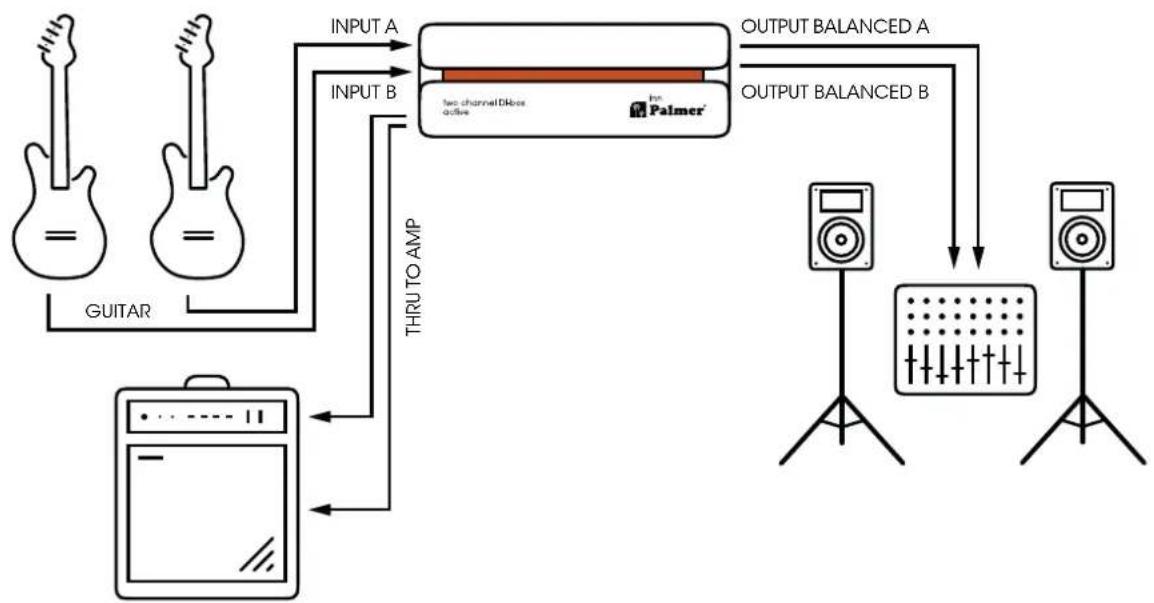
flowchart
graph TD
    A["Guitar"] -->|INPUT A| B["THRU TO AMP"]
    B --> C["Two channel Dikes active"]
    C --> D["OUTPUT BALANCED A"]
    C --> E["OUTPUT BALANCED B"]
    E --> F["Speaker 1"]
    E --> G["Speaker 2"]
    F --> H["Output"]
    G --> I["Output"]
TECHNICAL DATA
GENERAL
| Product number PINN | |
| Product type DI box | |
| No. of channels 2 | |
| Type Active | |
| Transformer isolated Yes | |
| No. of inputs 2 | |
| Input type Unbalanced | |
| Input connectors 6.3 mm jack | |
| No. of outputs 2 | |
| Output type Balanced | |
| Output connectors XLR | |
| THRU outputs per channel 1 | |
| Input attenuation (PAD) | 0 dB/30 dB |
| Ground/lift switch | Yes |
| Additional functions | Additional mono output |
| Operating voltage | 2× P48 V, 9-24 V external power supply unit |
| Power consumption | 0.5 W |
| Housing | Aluminium continuous casting |
| Dimensions (H/W/D) | 140 × 50 × 128 mm |
| Weight | 0.72 kg |
| Ambient temperature (for operation) | -20°C ... 70°C |
| Relative air humidity | < 80% (non-condensing) |
| Included accessories | Rubber feet, inscription label |
| AUDIO | |
| Max. input level (< 1% THD, 20 Hz) | +11 dBu |
| Max. input level (< 1% THD, 1 kHz) | +11 dBu |
| Max. output level (< 1% THD, 1 kHz) | +5.5 dBu |
| Frequency response (±1 dB, relative 1 kHz) | 20 Hz-20 kHz |
| Input impedance (1 kHz, setting: 0 dB PAD) | 500 kΩ |
| Output impedance (1 kHz, setting: 0 dB PAD) | 110 Ω |
| THD+N (30 Hz, +4 dBu, unity, unweighted) | < 0.0028% |
| THD+N (1 kHz, +4 dBu, unity, unweighted) | < 0.0013% |
| IMD (SMPTE) (60 Hz/7 kHz, 4:1, +4 dBu) | < 0.0017% |
| SNR (+4 dBu, 22 kHz BW, unity, unweighted) | 108 dB |
| Transformer ratio | 1:3 |
All measurements were performed with a generator with an output impedance of 600 Ω and 1 kΩ balanced load.
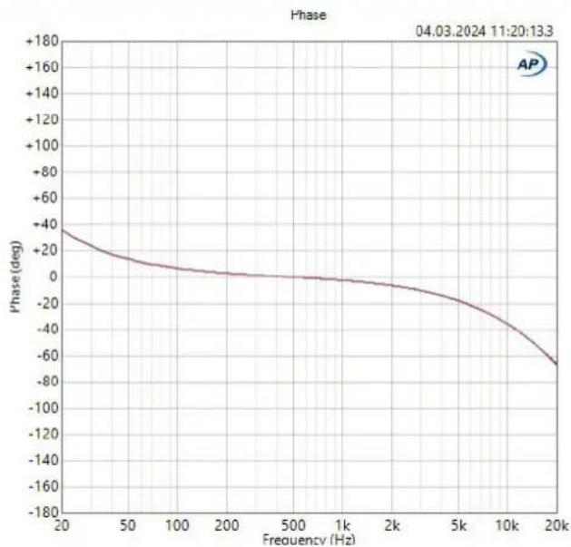
line
| Frequency (Hz) | Phase (deg) | | -------------- | ----------- | | 20 | +40 | | 50 | +20 | | 100 | 0 | | 200 | 0 | | 500 | 0 | | 1k | 0 | | 2k | -10 | | 5k | -30 | | 10k | -60 | | 20k | -80 |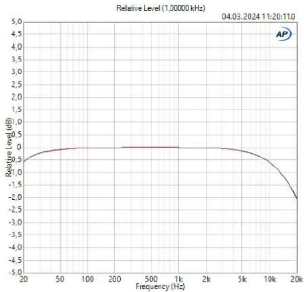
line
| Frequency (Hz) | Relative Level (dB) | | -------------- | ------------------- | | 20 | -0.5 | | 50 | 0.0 | | 100 | 0.0 | | 200 | 0.0 | | 500 | 0.0 | | 1k | 0.0 | | 2k | 0.0 | | 5k | -0.5 | | 10k | -1.5 | | 20k | -2.5 |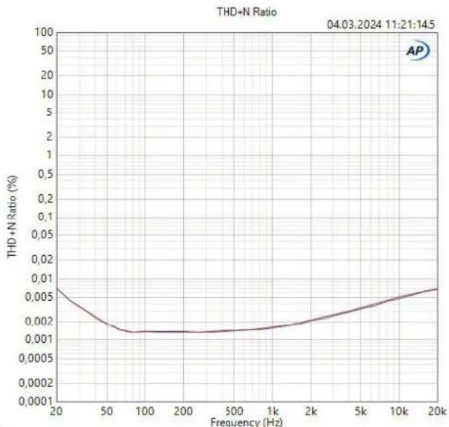
line
| Frequency (Hz) | THD+N Ratio (%) | | -------------- | --------------- | | 20 | 0.006 | | 50 | 0.002 | | 100 | 0.001 | | 200 | 0.001 | | 500 | 0.001 | | 1k | 0.0015 | | 2k | 0.002 | | 5k | 0.003 | | 10k | 0.004 | | 20k | 0.006 |CORRECT DISPOSAL OF THIS PRODUCT

PACKAGING:
- Packaging can be fed into the reusable material cycle using the usual disposal methods.
- Please separate the packaging in accordance with disposal laws and recycling regulations in your country.
DEVICE:
-
This device is subject to the European Waste Electrical and Electronic Equipment Directive in the currently valid version. WEEE Waste Electrical and Electronic Equipment Directive. Old appliances do not belong in household waste. The old device must be disposed of via an approved disposal company or a municipal disposal facility. Please observe the applicable regulations in your country!
-
Observe all disposal laws applicable in your country.
- As a private customer, you can obtain information on environmentally friendly disposal options from the seller of the product or the appropriate regional authorities.

BATTERIES:
- Batteries should not be disposed of in household waste. Batteries and recharge able batteries must be disposed of via an approved disposal company or a municipal disposal facility.
- Observe all disposal laws applicable in your country.
- As a private customer, you can obtain information on environmentally friendly disposal options from the seller of the product or through the relevant regional authorities.
- Devices with batteries that cannot be removed by the user must be taken to a collection point for electrical appliances.
MANUFACTURER'S DECLARATIONS
Our current warranty conditions and limitation of liability can be found at: cdn-shop.adamhall.com/media/pdf/Manufacturers-Declarations-PALMER_DE_EN_ES_FR.pdf
Contact your distribution partner for service.

CE CONFORMITY
Adam Hall GmbH hereby confirm that this product meets the following guidelines (where applicable): Low-Voltage Directive (2014/35/EU)
EMC Directive (2014/30/EU)
RoHS (2011/65/EU)
RED (2014/53/EU)
CE DECLARATION OF CONFORMITY
Declarations of conformity for products that are subject to the LVD, EMC, RoHS Directives, can be requested at info@adamhall.com.
Declarations of conformity for products that are subject to the RED Directive can be downloaded at www.adamhall.com/compliance/

FCC STATEMENT
This device complies with Part 15 of the FCC Rules. Operation is subject to the following two conditions: (1) This device may not cause harmful interference, and (2) This device must accept any interference received, including interference that may cause undesired operation.

UKCA- Conformity
Hereby, Adam Hall Ltd. declares that this product meets the following guidelines (where applicable) Electrical Equipment (Safety) Regulations 2016 Electromagnetic Compatibility Regulations 2016 (SI 2016/1091). The Restriction of the Use of Certain Hazardous Substances in Electrical and Electronic Equipment Regulation 2012 (SI 2012/3032) Radio Equipment Regulations 2017 (SI 2016/2015)
Adam Hall Ltd. | The Seedbed Bus. Centre | SS3 9QY Essex | UK
UKCA- DECLARATION OF CONFORMITY
Products that are subject to Electrical Equipment (Safety) Regulation 2016, EMC Regulation 2016 or RoHS Regulation can be requested at info@adamhall.com Products that are subject to the Radio Equipments Regulations 2017 (SI2017/1206) can be downloaded from www.adamhall.com/compliance/
SUBJECT TO MISPRINTS AND ERRORS, AS WELL AS TECHNICAL OR OTHER MODIFICATIONS!

natural_image
Front panel of a black electronic device with three GND connectors and labeled buttons (no readable text beyond labels)flowchart
graph LR
    A["Input: guitar"] -->|INPUT A| B["Two-channel microphone"]
    C["Input: guitar"] -->|INPUT B| B
    B --> D["Output: a speaker with balanced output"]
    D --> E["Output: a speaker with balanced output"]
flowchart
graph TD
    A["Guitar"] -->|INPUT A| B["THRU TO AMP"]
    B --> C["Two channel Dikes active"]
    C --> D["OUTPUT BALANCED A"]
    C --> E["OUTPUT BALANCED B"]
    E --> F["Speaker 1"]
    E --> G["Speaker 2"]
    F --> H["Output"]
    G --> I["Output"]
TECHNISCHE DATEN
ALLGEMEIN
natural_image
Front panel of a black electronic device with three GND connectors and labeled buttons (no readable text beyond labels)CONNECTEURS, COMMANDES ET INDICATEURS - PANNEAU ARRIÈRE
5. LIFT / GND A - LIFT / GND B - LIFT / GND A+B
DÉCLARATION DE CONFORMITÉ CE
natural_image
Front panel of a black electronic device with three GND connectors and labeled buttons (no readable text beyond labels)CONEXIONES, CONTROLES E INDICADORES: PANEL POSTERIOR
5. LIFT / GND A - LIFT / GND B - LIFT / GND A+B
flowchart
graph LR
    A["Input: guitar"] -->|INPUT A| B["Two-channel microphone"]
    C["Input: guitar"] -->|INPUT B| B
    B --> D["Output: a speaker with balanced output"]
    D --> E["Output: a speaker with balanced output"]
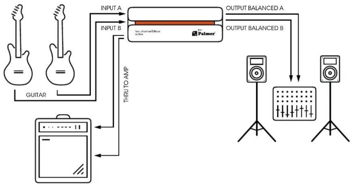
flowchart
graph TD
    A["Guitar"] -->|INPUT A| B["THRU TO AMP"]
    B --> C["Two channel Dikes active"]
    C --> D["OUTPUT BALANCED A"]
    C --> E["OUTPUT BALANCED B"]
    E --> F["Speaker 1"]
    E --> G["Speaker 2"]
    F --> H["Output"]
    G --> I["Output"]
CARACTERÍSTICAS TÉCNICAS
GENERAL
natural_image
Front panel of a black electronic device with three GND connectors and labeled buttons (no readable text beyond labels)ZŁĄCZA, ELEMENTY OBSŁUGOWE I WYŚWIETLACZE - PANEL TYLNY
5. LIFT / GND A - LIFT / GND B - LIFT / GND A+B
flowchart
graph TD
    A["Guitar"] -->|INPUT A| B["THRU TO AMP"]
    C["Guitar"] -->|INPUT B| B
    B --> D["Two channel blocks active"]
    D --> E["OUTPUT BALANCED A"]
    D --> F["OUTPUT BALANCED B"]
    E --> G["Speaker with grid"]
    F --> H["Speaker with grid"]
    G --> I["Output"]
    H --> J["Output"]
SPECYFIKACJE TECHNICZNE
OGÓLNA CHARAKTERYSTYKA
natural_image
Front panel of a black electronic device with three GND connectors and labeled buttons (no readable text beyond labels)CONEXIONES, CONTROLES E INDICADORES: PANEL POSTERIOR
5. LIFT / GND A - LIFT / GND B - LIFT / GND A+B
flowchart
graph LR
    A["Speaker with guitar"] -->|INPUT A| B["Two Channel DAC-ox active"]
    C["Speaker with microphone"] -->|INPUT B| B
    B --> D["Output Balanced A"]
    B --> E["Output Balanced B"]
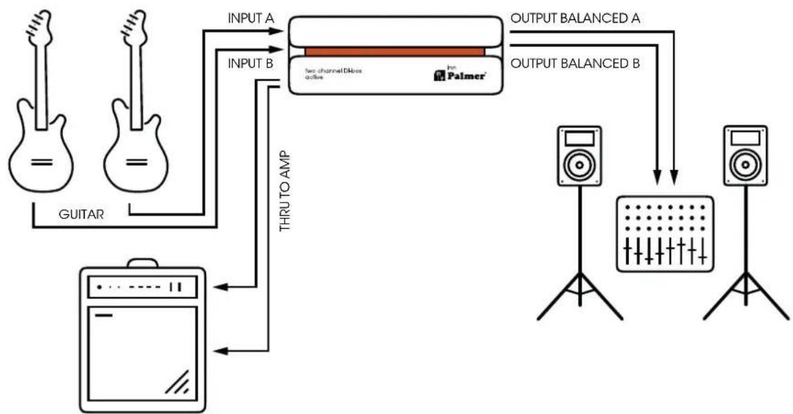
flowchart
graph TD
    A["Guitar"] --> B["THRU TO AMP"]
    B --> C["Two channel Dikos active"]
    C --> D["Output Balanced A"]
    C --> E["Output Balanced B"]
    D --> F["Speaker"]
    E --> G["Speaker"]
    F --> H["Signal Grid"]
    G --> I["Signal Grid"]
    J["Input A"] --> C
    K["Input B"] --> B
CARACTERÍSTICAS TÉCNICAS
GENERAL
- EN USER MANUAL 3
- inn
- Active two-channel DI box
- INFORMATION ON THIS USER MANUAL
- Carefully read the safety instructions and the entire manual before operating the device.
- INTENDED USE
- DEFINITIONS AND SYMBOL EXPLANATIONS
- SAFETY INSTRUCTIONS
- DANGER:
- ATTENTION:
- WARNING:
- CAUTION:
- ATTENTION: HIGH-VOLUME AUDIO PRODUCTS!
- PLEASE NOTE FOR PORTABLE INDOOR DEVICES:
- PACKAGING CONTENT
- INTRODUCTION
- CONNECTIONS AND OPERATING/DISPLAY ELEMENTS - FRONT
- THRU A/THRU B
- PAD A/PAD B (passive attenuation device)
- DC 9-24 V
- CONNECTIONS AND OPERATING/DISPLAY ELEMENTS - BACK
- LIFT / GND A - LIFT / GND B - LIFT / GND A+B
- OUTPUT A/OUTPUT B
- OUTPUT A+B
- PLEASE NOTE
- TECHNICAL DATA
- CORRECT DISPOSAL OF THIS PRODUCT
- PACKAGING:
- DEVICE:
- BATTERIES:
- MANUFACTURER'S DECLARATIONS
- CE CONFORMITY
- CE DECLARATION OF CONFORMITY
- FCC STATEMENT
- UKCA- Conformity
- UKCA- DECLARATION OF CONFORMITY
- TECHNISCHE DATEN
- CONNECTEURS, COMMANDES ET INDICATEURS - PANNEAU ARRIÈRE
- DÉCLARATION DE CONFORMITÉ CE
- CONEXIONES, CONTROLES E INDICADORES: PANEL POSTERIOR
- CARACTERÍSTICAS TÉCNICAS
- ZŁĄCZA, ELEMENTY OBSŁUGOWE I WYŚWIETLACZE - PANEL TYLNY
- SPECYFIKACJE TECHNICZNE
Brand : Palmer
Model : RIVER inn
Category : Audio Equipment