
PROGYS 400 TRI - Welding machine GYS - Free user manual and instructions
Find the device manual for free PROGYS 400 TRI GYS in PDF.

| Brand | GYS |
| Model | PROGYS 400 TRI |
| Product type | Welding inverter |
| Welding processes | MMA (stick), TIG Lift |
| Power supply | Three-phase 400 V ± 15%, 50-60 Hz, 32 A plug (EN 60309-1) |
| MMA welding current | Up to 400 A |
| TIG welding current | Up to 300 A |
| Protection rating | IP23 |
| Operating temperature range | -10 °C to +40 °C |
| Storage temperature range | -20 °C to +55 °C |
| Maximum humidity | 50% at 40 °C, 90% at 20 °C |
| Maximum altitude | 1000 m |
| Special functions | VRD, Anti-Sticking, Hot Start, Arc Force, remote control |
| Ventilation | Temperature controlled |
| MMA electrode types | Rutile, basic, cellulosic, stainless steel, cast iron |
| MMA electrode diameters | 1.6 mm to 6.3 mm |
| TIG shielding gas | Argon |
| Extension cable cross-section | 4 mm² up to 45 m |
| Warranty | 2 years (parts and labor) |
Frequently Asked Questions - PROGYS 400 TRI GYS
User questions about PROGYS 400 TRI GYS
0 question about this device. Answer the ones you know or ask your own.
Ask a new question about this device
Download the instructions for your Welding machine in PDF format for free! Find your manual PROGYS 400 TRI - GYS and take your electronic device back in hand. On this page are published all the documents necessary for the use of your device. PROGYS 400 TRI by GYS.
USER MANUAL PROGYS 400 TRI GYS
natural_image
Line drawing of a portable industrial machine with control panel and ventilation slots (no text or symbols)FR 2 / 3-10 / 67-76
EN 2 / 11-18 / 67-76
DE 2 / 19-26 / 67-76
ES 2 / 27-34 / 67-76
RU 2 / 35-42 / 67-76
NL 2 / 43-50 / 67-76
IT 2 / 51-58 / 67-76
PL 2 / 59-66 / 67-76
PROGYS 300 TRI PROGYS 400 TRI
Poste à souder MMA triphasé Three-phase MMA generator Dreiphasiges E-hand-schweissgerät Equipo de soldadura MMA trifásico Трехфазный сварочный аппарат MMA Driefasen MMA lasapparaat Sorgente di saldatura MMA trifase Trójfazowe stanowisko do spawania MMA
FIG-1
PROGYS 300 TRI
PROGYS 400 TRI
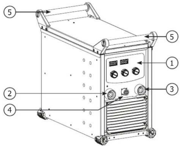
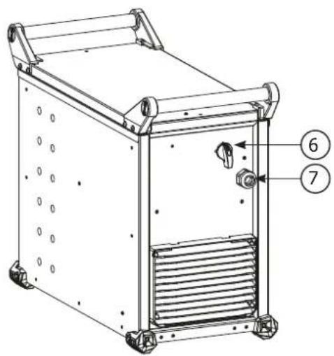
FIG-2
AVERTISSEMENTS - RÈGLES DE SÉCURITÉ
CONSIGNE GÉNÉRALE

INSTALLATION – FONCTIONNEMENT PRODUIT
INTERFACE HOMME MACHINE (IHM) (FIG-2)
ANOMALIES, CAUSES, REMÈDES
Read and understand the following safety recommendations before using or servicing the unit. Any change or servicing that is not specified in the instruction manual must not be undertaken.
The manufacturer is not liable for any injury or damage caused due to non-compliance with the instructions featured in this manual. In the event of problems or uncertainties, please consult a qualified person to handle the installation properly.
ENVIRONMENT
This equipment must only be used for welding operations in accordance with the limits indicated on the descriptive panel and/or in the user manual. The operator must respect the safety precautions that apply to this type of welding. In case of inedaquate or unsafe use, the manufacturer cannot be held liable for damage or injury.
This equipment must be used and stored in a place protected from dust, acid or any other corrosive agent. Operate the machine in an open, or well-ventilated area.
Operating temperature:
Use between -10 and +40°C (+14 and +104°F).
Store between -20 and +55°C (-4 and 131°F).
Air humidity:
Lower or equal to 50% at 40°C (104°F).
Lower or equal to 90% at 20°C (68°F).
Altitude:
Up to 1000 meters above sea level (3280 feet).
PROTECTION OF THE INDIVIDUALS
Arc welding can be dangerous and can cause serious and even fatal injuries.
Welding exposes the user to dangerous heat, arc rays, electromagnetic fields, noise, gas fumes, and electrical shocks. People wearing pacemakers are advised to consult with their doctor before using this device.
To protect oneself as well as the other, ensure the following safety precautions are taken:

In order to protect you from burns and radiations, wear clothing without cuffs. These clothes must be insulated, dry, fireproof and in good condition, and cover the whole body.

Wear protective gloves which guarantee electrical and thermal insulation.

Use sufficient welding protective gear for the whole body: hood, gloves, jacket, trousers... (varies depending on the application/operation). Protect the eyes during cleaning operations. Do not operate whilst wearing contact lenses. It may be necessary to install fireproof welding curtains to protect the area against arc rays, weld spatters and sparks.
Inform the people around the working area to never look at the arc nor the molten metal, and to wear protective clothes.

Ensure ear protection is worn by the operator if the work exceeds the authorised noise limit (the same applies to any person in the welding area).
Stay away from moving parts (e.g. engine, fan...) with hands, hair, clothes etc... Never remove the safety covers from the cooling unit when the machine is plugged in - The manufacturer is not responsible for any accident or injury that happens as a result of not following these safety precautions.
The pieces that have just been welded are hot and may cause burns when manipulated. During maintenance work on the torch or the electrode holder, you should make sure it's cold enough and wait at least 10 minutes before any intervention. The cooling unit must be on when using a water cooled torch in order to ensure that the liquid does not cause any burns.
ALWAYS ensure the working area is left as safe and secure as possible to prevent damage or accidents.
WELDING FUMES AND GAS

The fumes, gases and dust produced during welding are hazardous. It is mandatory to ensure adequate ventilation and/or extraction to keep fumes and gases away from the work area. An air fed helmet is recommended in cases of insufficient air supply in the workplace.
Check that the air intake is in compliance with safety standards.
Care must be taken when welding in small areas, and the operator will need supervision from a safe distance. Welding certain pieces of metal containing lead, cadmium, zinc, mercury or beryllium can be extremely toxic. The user will also need to degrease the workpiece before welding.
Gas cylinders must be stored in an open or ventilated area. The cylinders must be in a vertical position secured to a support or trolley.
Do not weld in areas where grease or paint are stored.
FIRE AND EXPLOSION RISKS

Protect the entire welding area. Compressed gas containers and other inflammable material must be moved to a minimum safe distance of 11 meters. A fire extinguisher must be readily available.
Be careful of spatter and sparks, even through cracks. It can be the source of a fire or an explosion.
Keep people, flammable objects and containers under pressure at a safe distance.
Welding of sealed containers or closed pipes should not be undertaken, and if opened, the operator must remove any inflammable or explosive materials (oil, petrol, gas...).
Grinding operations should not be directed towards the device itself, the power supply or any flammable materials.
GAS BOTTLE

Gas leaking from the cylinder can lead to suffocation if present in high concentrations around the work area.
Transport must be done safely: Cylinders closed and product off. Always keep cylinders in an upright position securely chained to a fixed support or trolley.
Close the bottle after any welding operation. Be wary of temperature changes or exposure to sunlight.
Cylinders should be located away from areas where they may be struck or subjected to physical damage.
Always keep gas bottles at a safe distance from arc welding or cutting operations, and any source of heat, sparks or flames.
Be careful when opening the valve on the gas bottle, it is necessary to remove the tip of the valve and make sure the gas meets your welding requirements.
ELECTRIC SAFETY

The machine must be connected to an earthed electrical supply. Use the recommended fuse size.
An electrical discharge can directly or indirectly cause serious or deadly accidents.
Do not touch any live part of the machine (inside or outside) when it is plugged in (Torches, earth cable, cables, electrodes) because they are connected to the welding circuit.
Before opening the device, it is imperative to disconnect it from the mains and wait 2 minutes, so that all the capacitors are discharged.
Do not touch the torch or electrode holder and earth clamp at the same time.
Damaged cables and torches must be changed by a qualified and skilled professional. Make sure that the cable cross section is adequate with the usage (extensions and welding cables). Always wear dry clothes in good condition, in order to be insulated from the electrical circuit. Wear insulating shoes, regardless of the environment in which you work in.
EMC CLASSIFICATION

These Class A devices are not intended to be used on a residential site where the electric current is supplied by the public network, with a low voltage power supply. There may be potential difficulties in ensuring electromagnetic compatibility on these sites, because of the interferences, as well as radio frequencies.

This equipment complies with the IEC 61000-3-11 standard.
This equipment does not comply with IEC 61000-3-12 and is intended to be connected to private low-voltage systems interfacing with the public supply only at the medium- or high-voltage level. On a public low-voltage power grid, it is the responsibility of the installer or user of the device to ensure, by checking with the operator of the distribution network, which device can be connected.
ELECTROMAGNETIC INTERFERENCES
The electric currents flowing through a conductor cause electrical and magnetic fields (EMF). The welding current generates an EMF field around the welding circuit and the welding equipment.
The EMF fields may disrupt some medical implants, such as pacemakers. Protection measures should be taken for people wearing medical implants. For example, access restrictions for passers-by or an individual risk evaluation for the welders.
All welders should take the following precautions in order to minimise exposure to the electromagnetic fields (EMF) generated by the welding circuit::
- position the welding cables together – if possible, attach them;
- keep your head and torso as far as possible from the welding circuit;
- never enroll the cables around your body;
- never position your body between the welding cables. Hold both welding cables on the same side of your body;
- connect the earth clamp as close as possible to the area being welded;
- do not work too close to, do not lean and do not sit on the welding machine
- do not weld when you're carrying the welding machine or its wire feeder.
People wearing pacemakers are advised to consult their doctor before using this device.
Exposure to electromagnetic fields while welding may have other health effects which are not yet known.
RECOMMANDATIONS TO ASSES THE AREA AND WELDING INSTALLATION
Overview
The user is responsible for installing and using the arc welding equipment in accordance with the manufacturer's instructions. If electromagnetic disturbances are detected, it is the responsibility of the user of the arc welding equipment to resolve the situation with the manufacturer's technical assistance. In some cases, this remedial action may be as simple as earthing the welding circuit. In other cases, it may be necessary to construct an electromagnetic shield around the welding power source and around the entire piece by fitting input filters. In all cases, electromagnetic interferences must be reduced until they are no longer bothersome.
Welding area assessment
Before installing the machine, the user must evaluate the possible electromagnetic problems that may arise in the area where the installation is planned.
. In particular, it should consider the following:
a) the presence of other power cables (power supply cables, telephone cables, command cable, etc...) above, below and on the sides of the arc welding machine.
b) television transmitters and receivers ;
c) computers and other hardware;
d) critical safety equipment such as industrial machine protections;
e) the health and safety of the people in the area such as people with pacemakers or hearing aids;
f) calibration and measuring equipment
g) The isolation of the equipment from other machinery.
The user will have to make sure that the devices and equipments that are in the same room are compatible with each other. This may require extra precautions;
h) make sure of the exact hour when the welding and/or other operations will take place.
The surface of the area to be considered around the device depends on the building's structure and other activities that take place there. The area taken in consideration can be larger than the limits determined by the companies.
Welding area assessment
Besides the welding area, the assessment of the arc welding systems installation itself can be used to identify and resolve cases of disturbances. The assessment of emissions must include in situ measurements as specified in Article 10 of CISPR 11. In situ measurements can also be used to confirm the effectiveness of mitigation measures.
RECOMMENDATION ON METHODS OF ELECTROMAGNETIC EMISSIONS REDUCTION
a. National power grid: The arc welding machine must be connected to the national power grid in accordance with the manufacturer's recommendation. If interferences occur, it may be necessary to take additional preventive measures such as the filtering of the power supply network. Consideration should be given to shielding the power supply cable in a metal conduit. It is necessary to ensure the shielding's electrical continuity along the cable's entire length. The shielding should be connected to the welding current's source to ensure good electrical contact between the conduct and the casing of the welding current source.
b. Maintenance of the arc welding equipment: The arc welding machine should be submitted to a routine maintenance check according to the manufacturer's recommendations. All accesses, service doors and covers should be closed and properly locked when the arc welding equipment is on.. The arc welding equipment must not be modified in any way, except for the changes and settings outlined in the manufacturer's instructions. The spark gap of the arc start and arc stabilization devices must be adjusted and maintained according to the manufacturer's recommendations.
c. Welding cables: Cables must be as short as possible, close to each other and close to the ground, if not on the ground.
d. Electrical bonding : consideration should be given to bonding all metal objects in the surrounding area. However, metal objects connected to the workpiece increase the riskof electric shock if the operator touches both these metal elements and the electrode. It is necessary to insulate the operator from such metal objects.
e. Earthing of the welded part: When the part is not earthed - due to electrical safety reasons or because of its size and its location (which is the case with ship hulls or metallic building structures), the earthing of the part can, in some cases but not systematically, reduce emissions It is preferable to avoid the earthing of parts that could increase the risk of injury to the users or damage other electrical equipment. If necessary, it is appropriate that the earthing of the part is done directly, but in some countries that do not allow such a direct connection, it is appropriate that the connection is made with a capacitor selected according to national regulations.
f. Protection and plating : The selective protection and plating of other cables and devices in the area can reduce perturbation issues. The protection of the entire welding area can be considered for specific situations.
TRANSPORT AND TRANSIT OF THE WELDING MACHINE
The machine is fitted with handle(s) to facilitate transportation. Be careful not to underestimate the machine's weight.
30^
Do not use the cables or torch to move the machine. The welding equipment must be moved in an upright position.
Do not place/carry the unit over people or objects. Never lift the machine while there is a gas cylinder on the support shelf. A clear path is available when moving the item.
EQUIPMENT INSTALLATION
- Put the machine on the floor (maximum incline of 10^ .)
- Ensure the work area has sufficient ventilation for welding, and that there is easy access to the control panel.
- The machine must not be used in an area with conductive metal dusts.
- The machine must be placed in a sheltered area away from rain or direct sunlight.
• The machine protection level is IP23, which means : - Protection against access to dangerous parts from solid bodies of a ≥12.5mm diameter and,
- Protection against the rain inclined at 60^ towards the vertical.
These devices can be used outside in accordance with the IP23 protection index. - The power cables, extensions and welding cables must be fully uncoiled to prevent overheating.

The manufacturer does not incur any responsibility regarding damages to both objects and persons that result from an incorrect and/or dangerous use of the machine.
MAINTENANCE / RECOMMENDATIONS


- Maintenance should only be carried out by a qualified person. Annual maintenance is recommended.
-
Ensure the machine is unplugged from the mains, and wait for two minutes before carrying out maintenance work. DANGER High Voltage and Currents inside the machine.
-
Remove the casing 2 or 3 times a year to remove any excess dust. Take this opportunity to have the electrical connections checked by a qualified person, with an insulated tool.
- Regularly check the condition of the power supply cable. If the power cable is damaged, it must be replaced by the manufacturer, its after sales service or an equally qualified person.
- Ensure the ventilation holes of the device are not blocked to allow adequate air circulation.
- Do not use this equipment to thaw pipes, to charge batteries, or to start any engine.
INSTALLATION – PRODUCT OPERATION
Only qualified personnel authorized by the manufacturer should perform the installation of the cutting equipment. During set up, the operator must ensure that the machine is unplugged. Connecting generators in a series or a parallel circuit is forbidden.
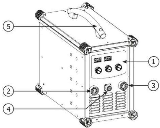
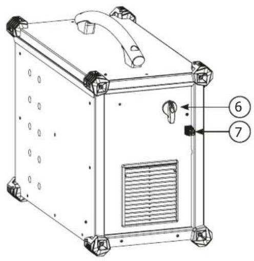
HARDWARE DESCRIPTION (FIG-1)
The PROGYS 300/400 is a three phase inverter welder which, depending on its equipment, can do :
- Electrode welding (MMA)
- Tungsten electrode welding (TIG)
The TIG process requires gas shielding (Argon).
The MMA process can weld any type of electrode : rutile, basic, cellulosic, stainless and brass.
The PROGYS 300/400 can be equipped with a remote control (ref. 045675).
1- Man to Machine Interface 5- Transport and lifting handles
2- - polarity plug 6- On/off switch
3- + polarity plug 7- Power supply cable
4- Remote control cable connector
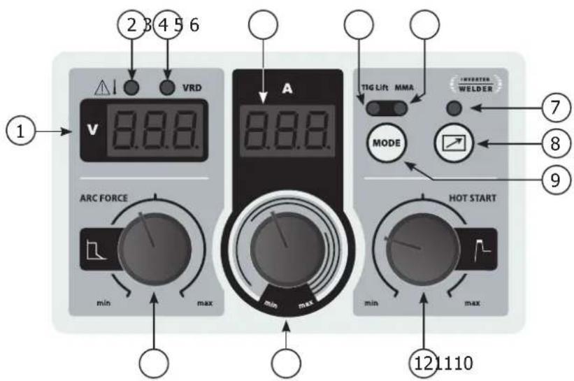
CONTROL BOARD (MMI) (FIG-2)
1- Voltage display 7- Active remote control indicator
2- Overheat indicator 8- Remote control activation button
3- Indicator of the functioning of the risk reduction device (VRD)
4- Current display 10- Adjustment knob for Arc Force parameter
5- TIG-LIFT mode indicator 11- Current adjustment knob
6- MMA mode indicator 12- Adjustment knob for Hot Start parameter
9- Mode selection button (MMA / TIG-LIFT)
POWER SUPPLY
- The PROGYS 300 is fitted with a 32 A socket type EN 60309-1 which must be connected to a three-phase 400V (50 - 60 Hz) power supply fitted with four wires and one earthed neutral.
- The PROGYS 400 is fitted with a 32 A socket type EN 60309-1 which must be connected to a three-phase 400V (50 - 60 Hz) power supply fitted with four wires and one earthed neutral.
- The absorbed effective current (I1eff) is displayed on the machine, for optimal use. Check that the power supply and its protection (fuse and/or circuit breaker) are compatible with the current needed by the machine. In some countries, it may be necessary to change the plug to allow the use at maximum settings.
- While under intensive use (superior to the duty cycle) the thermal protection can activate, in that case, the arc switches off and the thermal protection indicator switches on.
- The machine ie designed to work on a 400V +/- 15% power supply.
- The start is done via an on / off switch (FIG 1 - 6) set to I, and the stop is done by switching it to O. Attention ! Never disconnect the power supply when the machine is on.
CONNECTION ON A GENERATOR
The machine can work with generators as long as the auxiliary power matches these requirements :
- The voltage must be AC, always superior to 400 Vac ±15%, and the peak voltage below 700V,
- The frequency must be between 50 and 60 Hz.
It is imperative to check these requirements as several generators generate high voltage peaks that can damage these machines.
USE WITH EXTENSION CABLES
All extension cables must have an adequate size and section, relative to the machine's voltage.
Use an extension that complies with national safety regulations.
| Input voltage Wire section of extension cord (<45m) | ||
| PROGYS 300 | 400 V - 3~ | 2.5 mm ^2 |
| PROGYS 400 4 mm ^2 | ||
ELECTRODE WELDING (MMA)
CONNECTIONS AND RECOMMENDATIONS
- Connect the cables, electrode holder and earth clamp in the connectors,
- Respect the welding polarities and intensities indicated on the electrodes boxes,
- Remove the electrode from the electrode holder when the machine is not in use.
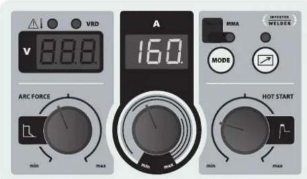
MMA
The grey areas are not useful for this mode.
MODE SELECTION
Press the button 📂 select the MMA mode.
MAIN SETTINGS
1. Welding intensity settings :
Adjust the welding current using the central knob according to the electrode diameter and the type of assembly to be carried out. The current setpoint is indicated on the right side display.
Adjust the arcforce level with the left side knob. The lower the arcforce level, the softer the arc will be. The higher the arcforce level, the higher the welding overcurrent will be. It is recommended to set the arc force in median position to start the welding and adjust it according to the results and welding preferences. Note: the arcforce setting range is specific to the selected electrode type.
3. Hot Start settings :
Adjust the Hot Start level with the right side knob. Low Hot start, for thin sheets and High Hot start for difficult-to-weld metals (dirty or oxydised).
WELDING PARAMETERS
WELDING INTENSITY SETTINGS
The following settings concern the intensity range that may be used depending on the electrode's type and diameter. These ranges are quite large as they depend on the application and the welding position.
| ∅ electrode (mm) | Rutile E6013 (A) | Basic E7018 (A) | Cellulosic E6010 (A) |
| 1.6 30-60 30-55 - | |||
| 2.0 50-70 50-80 - | |||
| 2.5 60-100 80-110 60-75 | |||
| 3.15 80-150 90-140 85-90 | |||
| 4.0 100-200 125-210 120-160 | |||
| 5 150-290 200-260 110-170 | |||
| 6.3 200-385 220-340 - | |||
ELECTRODE WELDING
- The reverse polarity cable must be disconnected in MMA (stick welding) mode in order to connect the electrode holder and earth clamp. Connect the electrode holder and earth clamp as indicated on the electrode packaging.
- Respect the basic rules of welding.
- This device has 1 feature specific to Inverter machines :
- Anti-Sticking: Enables easy removal of the electrode from the metal. The anti-sticking feature, after its start, requires approximately a 3 seconds delay before resuming normal welding operations.
CONNECTIONS AND RECOMMENDATIONS
TIG welding requires a torch as well as a gas bottle equipped with a regulator.
- Connect the earth clamp to the positive connector (+).
- Connect the torch's earth cable to the negative plug (-).
- Connect the torch's gas hose to the regulator's output.
Ensure that the torch is equipped and ready to weld, and that the consumables (Vise grip, ceramic gas nozzle, collet and collet body) are not damaged.
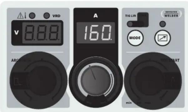
TIG
The grey areas are not useful for this mode.
MODE SELECTION
Press the button MoFA select the TIG mode.
Welding intensity settings :
Adjust the welding current using the central knob according to the diameter and the type of assembly to be carried out. The current setpoint is indicated on the right side display.
ARC STRIKE / IGNITION :
LIFT start : Using the torch, make contact between the electrode and the metal piece, then slightly lift the electrode to start the arc.
WELD STOP / SWITCHING TO DOWNSLOPE :
To stop the weld, slightly lift the torch, the intensity will gradually reduce (downslope).
ASSISTANCE FOR SETTING UP AND SELECTING CONSUMABLES
| DC | Current (A) Electrode (mm) Shroud (mm) | Argon flow rate (L/min) | ||||
| 0.3 - 3 mm 5 - 75 | 1 6.5 6 - 7 | |||||
| 2.4 - 6 mm 60 - 150 | 1.6 | 8 | 6 - 7 | |||
| 4 - 8 mm | 100 - 200 | 2 9.5 7 - 8 | ||||
| 6.8 - 8.8 mm | 170 - 220 | 2.4 | 11 8 - 9 | |||
| 9 - 12 mm | 255 - 300 | 3.2 | 12.5 | 9 - 10 | ||
ELECTRODE GRINDING
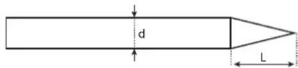
L = 3 x d for a low current.
L = 3 x d for a high current
REMOTE CONTROL
The remote control operates in TIG mode and in MMA.
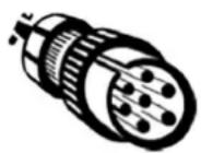
ref. 045699 External view
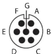
Electrical diagram for remote control.
Connection :
1- Plug the remote control into the connection at the front of the machine (FIG 1 - 4).
2- Press the button to activate the remote control. The ON LED lights up.
Connection :
The PROGYS 300/400 is equipped with a female socket for a remote control.
The specific 7-pin plug (option ref. 045699) allows a manual remote control to be connected to it. For the cabling layout, please see the diagram below.
| REMOTE CONTROL TYPE Wire description Pin | ||
| Manual remote control | 12 V A | |
| Cursor B | ||
| Common/Earth C | ||
Operating :
- Manual remote control (option ref. 045675)
The remote control enables the variation of current from 50% to 100% of the set intensity.
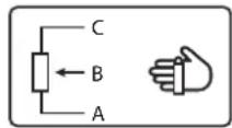
VRD (VOLTAGE REDUCTION DEVICE)
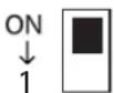
By default (factory setting), the VRD switch is in the ON position. To activate the VRD, in order to lower the no-load voltage of the generator (< 20 V), the switch on the control board must be toggled to 1 (page 67 - n°14/ page 68 - n°11). The HMI indicator light (FIG 2 - N°3) lights up.
To access the VRD switch (see page 69):

ELECTRIC SHOCKS CAN BE FATAL
- Disconnect the product from the power supply.
- Remove the 9 screws to open the side of the machine.
- Locate the red switch in the centre of the control board.
ADVICE & THERMAL PROTECTION
This device is equipped with a ventilator regulated by the inside temperature. When the machine's thermal protection is activated, it will not deliver any current. Yellow light (FIG 2 - 2) will turn on until the temperature of the machine has returned to normal.
- Do not block/cover the ventilation holes, ensure free flow of air.
- Whilst in thermal protection mode leave the machine plugged into the mains after welding to allow it to cool.
General observations :
• Always respect the basic rules of welding.
- Always work in an adequately ventilated area.
- Do not work on a damp surface.
TROUBLESHOOTING
| Troubleshooting Causes Solutions | |||
| MMA-TIG | The machine does not deliver any current and the yellow thermal protection indicator is switched on (FIG 2 - 2). | The thermal protection has switched on. | Wait the end of the cooling cycle, about 2 min. The indicator (FIG 2 - 2) switches off. |
| The display (FIG 2 - 4) is on but the device does not deliver current. | The earth clamp, the electrode holder or the welding torch are not connected to the unit. | Check the connections | |
| The product is connected to the mains, you are feeling tingling when touching the case. | The earth contact is faulty. | Check the plug and the earth of your installation. | |
| The machine welds poorly. Polarity error | Check the recommended polarity (+/-) on the electrode box. | ||
| TIG | Unstable arc | Fault due to the tungsten electrode | Use an electrode size more suitable to the thickness of your metal. |
| Use an tungsten electrode properly prepared. | |||
| Gas flow too high Reduce the gas flow | |||
| The tungsten electrode becomes oxidized and tainted at the end of the welding | Welding area. Protect the welding area against | draught. | |
| Gas problem, or gas flow stops too early | Check and tighten every gas connection. Wait for the electrode to cool down before switching off the glas flow. | ||
| The electrode melts Polarity error Check that the earth is connected to the + | |||
WARRANTY
The warranty covers faulty workmanship for 2 years from the date of purchase (parts and labour).
The warranty does not cover:
- Transit damage.
- Normal wear of parts (eg. : cables, clamps, etc..).
- Damages due to misuse (power supply error, dropping of equipment, disassembling).
- Environment related failures (pollution, rust, dust).
In case of failure, return the unit to your distributor together with:
- The proof of purchase (receipt etc ...)
- A description of the fault reported
WAARSCHUWINGEN - VEILIGHEIDSINSTRUCTIES
ALGEMENE INSTRUCTIES

| 1 | Clavier / Keyboard / Bedienfeld / Teclado / Панель управления / Bedieningspaneel / Tastiera / Klawiatura | 53556 |
| 2 Load board B4062 | ||
| 3 Pied / Feet / Pié / Fuß / Ножка / Pootje / Piedino / Stopka 56120 | ||
| 4 | Inductance / Inductor / Drossel / Inductancia / Индуктивность / Inductie / Induttanza / Indukcyjność | C32564 |
| 5 | Transformateur de puissance / Main Transformer / Netztransformator / Transformador de potencia / Трансформатор мощности / Vermogenstransformator / Trasformatore di potenza / Transformator mocy | C32568 |
| 6 | Carte de redressement secondaire / Output rectifier circuit board / Sekundäre Gleichrichtungsplatine / Tarjeta de recuperación secundaria / Вторичная плата выпрямления / Secondaire printplaat / Carta di recupero secondaria / Karta rektyfikacji wtórnej | B4090 |
| 7 | Ventilateur / Fan / Lüfter / Ventilador / Вентилятор / Ventilator / Ventilatore / Wentylator | 51001 |
| 8 | Grille externe / External grill / Externes Gitter / Rejilla exterior / Внешняя решетка / Buitenste rooster / Griglia esterna / Kratka zewnętrzna | 51010 |
| 9 | Carte de puissance primaire / Power input circuit board / Primäre Leistungsplatine / Tarjeta de potencia primaria / Первичная силовая плата / Primaire voedingskaart / Scheda di potenza primaria / Płyta zasilania podstawowego | 53561 |
| 10 | Commutateur marche / arrêt / On/off switch / Schalter Start/Stop / Conmutador encendido / apagado / Переключатель ВКЛ/ ВЫКЛ / Schakelaar aan/uit / Commutatore avvio / arresto / Włącznik/wyłącznik | C51545 |
| 11 | Poignée / Handle / Handgriff / Mango / Ручка / Handvat / Impugnatura / Uchwyt | 56014 |
| 12 | Carte de contrôle des IGBT / IGBT control board / IGBT-Steuerplatine / Tarjeta de control IGBT / Плата управления IGBT / Controle-kaart IGBT / Scheda di controllo di IGBT / Płyta sterująca IGBT | 53565 |
| 13 | Transformateur auxiliaire / Auxiliary transformer / Hilfstransformator / Transformador auxiliar / Вспомогательный трансформатор / Hulptransformator / Trasformatore ausiliare / Transportator dodatkowy | 53562 |
| 14 | Carte de contrôle principale / Main control circuit board / Hauptsteuerplatine / Tarjeta de control principal / Основная плата управления / Primaire besturingskaart / Scheda di controllo principale / Główna płyta sterująca | B4088 |
| 15 | Carte d'affichage / Display circuit board / Anzeigeplatine / Tarjeta de visualización / Плата индикации / Printplaat / Scheda di visualizzazione / Karta graficzna | 53564 |
| 16 | Embase Texas / Texas base plate / Texas Grundplatte / Placa base de Texas / Texassкая опорная плита / Texas bodemplaat / Piastra di base in Texas / Złącze Texas | 51478 |
| 17 | Bouton noir / Black knob / Schwarze Taste / Botón negro / Черная кнопka / Zwarte knop / Pulsante nero / Czarny przycisk (∅ 31 mm x 3) | 73009 |
| 18 AC current transformer / Transformator prądowy AC C32505 | ||
| 19 | Modules IGBT / IGBT module / IGBT-Module / Módulo IGBT / Модули IGBT / Modules IGBT / Moduli IGBT / Moduły IGBT | C13379 |
| 20 | Pont redresseur / Diode bridge / Gleichrichtungsbrücke / Puente rectificador / Выпрямительный мост / Gelijkrichter punt / Ponte raddrizzatore / Mostek prostowniczy | 53567 |
| 21 | Carte CEM / EMC board / EMV-Platine / Tarjeta CEM / Плата CEM / Printplaat / Carta CEM / Karta EMC | 53568 |
| 22 | Cordon secteur / Power cord / Netzkabel / Cable de alimentación / Шнур питания / Stroomkabel / Cavo di alimentazione / Główny kabel | B3118 |
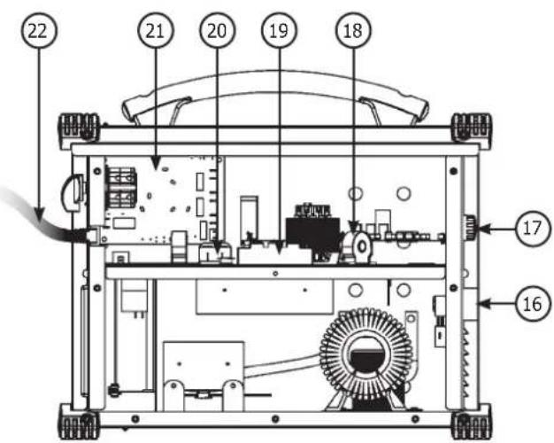
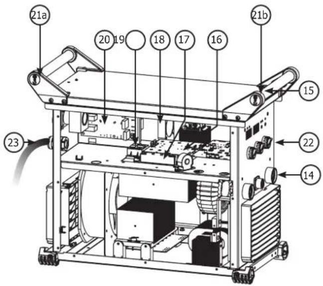
PIÈCES DE RECHANGE / SPARE PARTS / ERSATZTEILE / PIEZAS DE RECAMBIO / ЗАПЧАСТИ / RESERVE ONDERDELEN / PEZZI DI RICAMBIO / CZĘŚCI ZAMIENNE
PROGYS 400 TRI
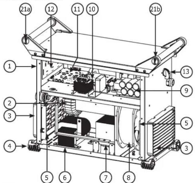
| 1 | Clavier / Keyboard / Bedienfeld / Teclado / Панель управления / Bedieningspaneel / Tastiera / Klawiatura | 53556 |
| 2 | Transformateur de puissance / Main Transformer / Netztransformator / Transformador de potencia / Трансформатор мощности / Vermogenstransformator / Trasformatore di potenza / Transportator mocy | 53557 |
| 3 | Grille externe / External grill / Externes Gitter / Rejilla exterior / Внешняя решетка / Buitenste rooster / Griglia esterna / Kratka zewnętrzna | 56094 |
| 4 Pied / Feet / Pié / Fuß / Ножка / Pootje / Piedino / Stopka 56120 | ||
| 5 | Grille interne / Internal grill / Internes Gitter / Rejilla interna / Внутренняя решетка / Binnenste rooster / Griglia interna / Kratka wewnętrzna | 56095 |
| 6 | Inductance / Inductor / Drossel / Inductancia / Индуктивность / Inductie / Induttanza / Indukcyjność | 53558 |
| 7 | Carte de redressement secondaire / Output rectifier circuit board / Sekundäre Gleichrichtungsplatine / Tarjeta de recuperación secundaria / Вторичная плата выпрямления / Secondaire printplaat / Carta di recupero secondaria / Karta rektyfikacji wtórnej | 53559 |
| 8 | Ventilateur / Fan / Lüfter / Ventilador / Вентилятор / Ventilator / Ventilatore / Wentylator | 53560 |
| 9 | Carte de puissance primaire / Power input circuit board / Primäre Leistungsplatine / Tarjeta de potencia primaria / Первичная силовая плата / Primaire voedingskaart / Scheda di potenza primaria / Płyta zasilania podstawowego | 53561 |
| 10 | Transformateur auxiliaire / Auxiliary transformer / Hilfstransformator / Transformador auxiliar / Вспомогательный трансформатор / Hulptransformator / Trasformatore ausiliare / Transportator dodatkowy | 53562 |
| 11 | Carte de contrôle principale / Main control circuit board / Hauptsteuerplatine / Tarjeta de control principal / Основная плата управления / Primaire besturingskaart / Scheda di controllo principale / Główna płyta sterująca | 53563 |
| 12 | Carte d'affichage / Display circuit board / Anzeigeplatine / Tarjeta de visualización / Плата индикации / Printplaat / Scheda di visualizzazione / Karta graficzna | 53564 |
| 13 | Commutateur marche / arrêt / On/off switch / Schalter Start/Stop / Conmutador encendido / apagado / Переключатель ВКЛ/ ВЫКЛ / Schakelaar aan/uit / Commutatore avvio / arresto / Włącznik/wyłącznik | 51061 |
| 14 | Embase Texas / Texas base plate / Texas Grundplatte / Placa base de Texas / Texасская опорная плита / Texas bodemplaat / Piastra di base in Texas / Złącze Texas | 51461 |
| 15 | Tube poignée / Handle tube / Griffrohr / Tubo del mango / Трубка ручки / Handgreep / Tubo maniglia / Rękojeść uchwytu | 90951GF |
| 16 | Carte de contrôle des IGBT / IGBT control board / IGBT-Steuerplatine / Tarjeta de control IGBT / Плата управления IGBT / Controle-kaart IGBT / Scheda di controllo di IGBT / Płyta sterująca IGBT | 53565 |
| 17 | Modules IGBT / IGBT module / IGBT-Module / Módulo IGBT / Модули IGBT / Modules IGBT / Moduli IGBT / Moduły IGBT | 53566 |
| 18 | Ventilateur auxiliaire / Auxiliary fan / Hilfslüfter / Ventilador auxiliar / Вспомогательный вентилятор / Hulpventilator / Ventilatore ausiliario / Wentylator pomocniczy | 51018 |
| 19 | Pont redresseur / Diode bridge / Gleichrichtungsbrücke / Puente rectificador / Выпрямительный мост / Gelijkrichter punt / Ponte raddrizzatore / Mostek prostowniczy | 53567 |
| 20 | Carte CEM / EMC board / EMV-Platine / Tarjeta CEM / Плата CEM / Printplaat / Carta CEM / Karta EMC | 53568 |
| 21 | Support de poignée / Handle support / Handgriffhalterung / Soporte mango / Подпорки ручки / Draaggreep / Supporto impugnatura / Wspornik uchwytu | a 56190b 56191 |
| 22 | Bouton noir / Black knob / Schwarze Taste / Botón negro / Черная кнопka / Zwarte knop / Pulsante nero / Czarny przycisk (∅ 31mm x 3) | 73009 |
| 23 | Cordon secteur / Power cord / Netzkabel / Cable de alimentación / Шнур питания / Stroomkabel / Cavo di alimentazione / Główny kabel | 21470 |
INTERRUPTEUR VRD / VRD SWITCH / VRD-EIN-AUS-SCHALTER / INTERRUPTOR VRD / VRD SCHAKELAAR / INTERRUTTORE VRD / WYŁĄCZNIK VRD
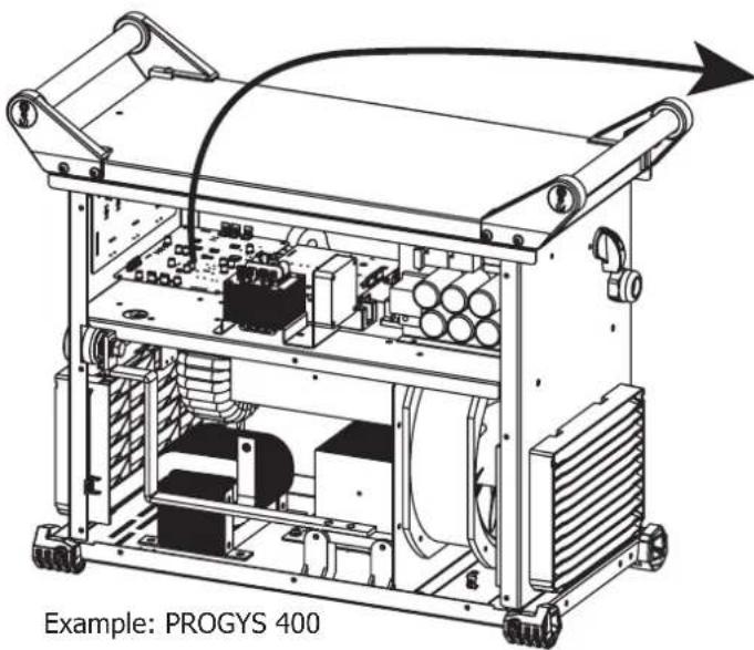
natural_image
Technical line drawing of a PROGYS 400 industrial machine with internal components and airflow direction arrow (no text or symbols on the device itself)
natural_image
Pure electrical circuit lines without any symbols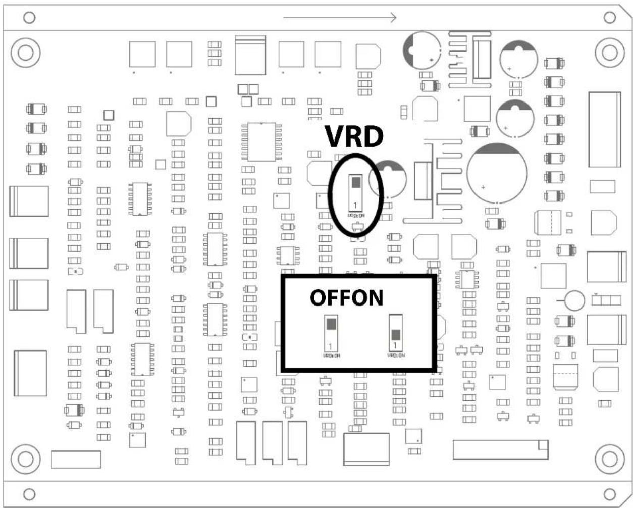
SCHÉMA ÉLECTRIQUE / CIRCUIT DIAGRAM / SCHALTPLAN / ESQUEMA ELÉCTRICO / ЭЛЕКТРИЧЕСКАЯ CXEMA / ELEKTRISCH SCHEMA / SCHEMA ELETTRICO / SCHEMAT ELEKTRYCZNY
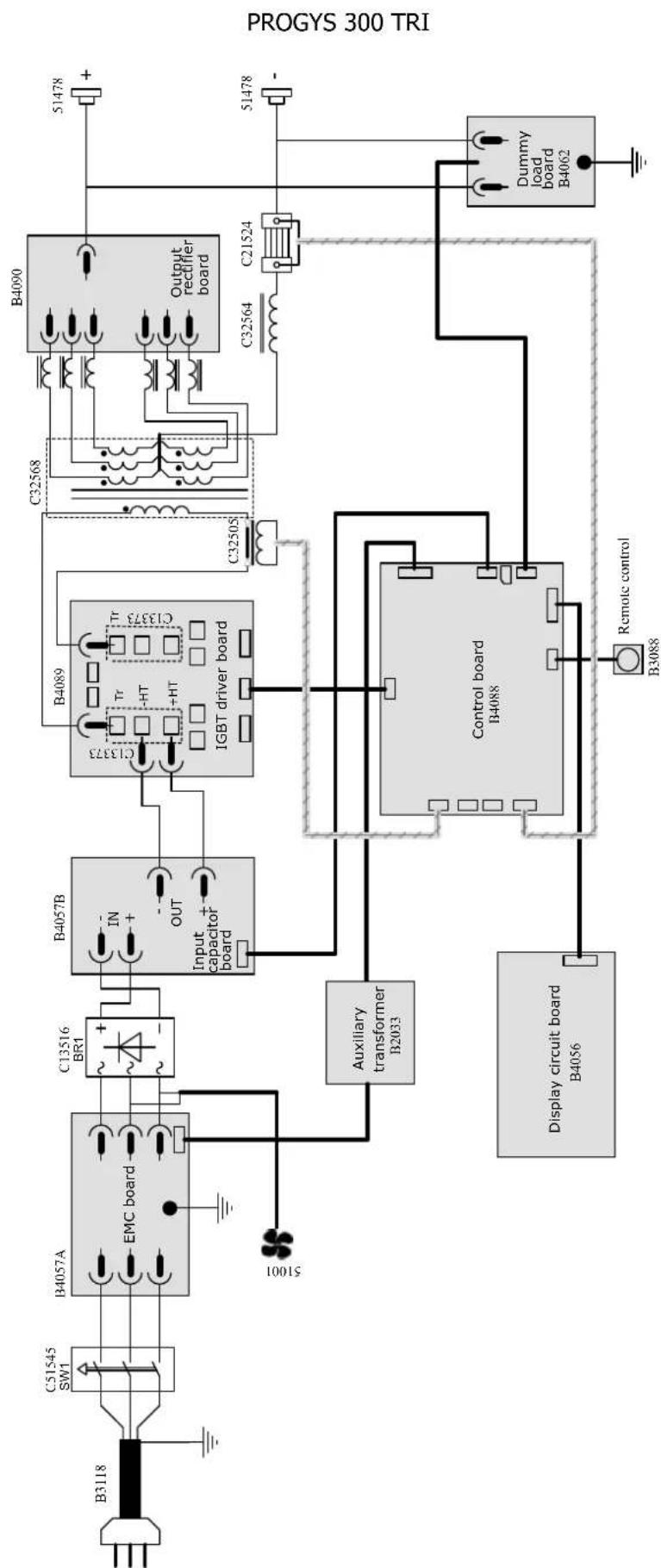
flowchart
graph TD
    A["PROGYS 300 TRI"] --> B["B4090"]
    A --> C["C32568"]
    A --> D["C32564"]
    A --> E["C3250S"]
    A --> F["B4089"]
    A --> G["C13373"]
    A --> H["IGBT driver board"]
    A --> I["Control board B408S"]
    A --> J["Auxiliary transformer B2033"]
    A --> K["Display circuit board B4056"]
    A --> L["Remote control B3088"]
    A --> M["C13516 BR1"]
    A --> N["EMC board"]
    A --> O["C51545 SW1"]
    A --> P["B3118"]
    B --> Q["S1478 +"]
    C --> R["S1478 -"]
    D --> S["C21524"]
    E --> T["C32568"]
    F --> U["IN + OUT + INPUT CAPACITOR BOARD"]
    G --> V["Ground"]
    H --> W["Ground"]
    I --> X["Ground"]
    J --> Y["Ground"]
    K --> Z["Ground"]
    L --> AA["Ground"]
    M --> AB["Ground"]
    N --> AC["Ground"]
    O --> AD["Ground"]
SCHÉMA ÉLECTRIQUE / CIRCUIT DIAGRAM / SCHALTPLAN / ESQUEMA ELÉCTRICO / ЭЛЕКТРИЧЕСКАЯ CXEMA / ELEKTRISCH SCHEMA / SCHEMA ELETTRICO / SCHEMAT ELEKTRYCZNY
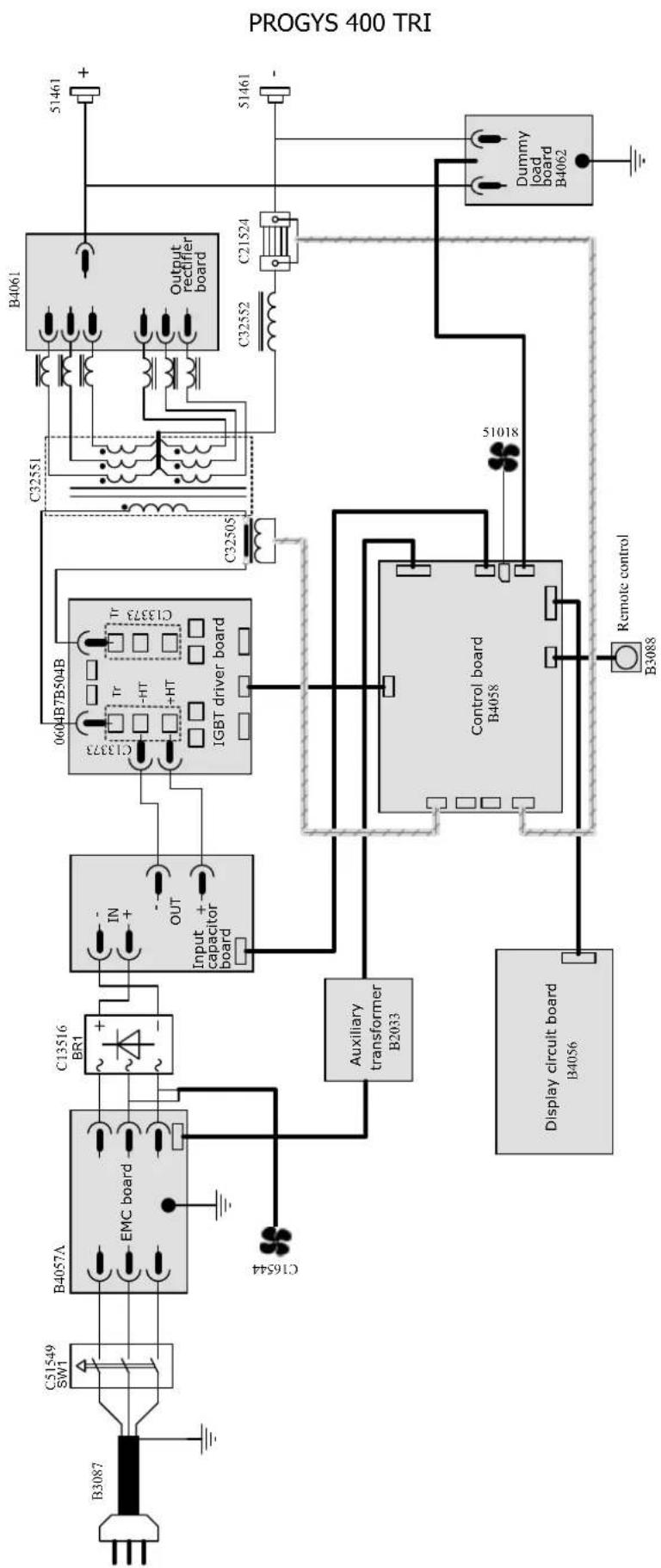
flowchart
graph TD
    A["PROGYS 400 TRI"] --> B["B4061"]
    A --> C["C32551"]
    A --> D["C32552"]
    A --> E["C32505"]
    A --> F["Output rectifier board"]
    A --> G["0604B7B504B"]
    A --> H["IGBT driver board"]
    A --> I["Control board B4058"]
    A --> J["Auxiliary transformer B2033"]
    A --> K["Display circuit board B4056"]
    A --> L["Remote control B3088"]
    A --> M["C13516 BR1"]
    A --> N["C16544"]
    A --> O["C51549 SW1"]
    A --> P["B3087"]
SPÉCIFICATIONS TECHNIQUES / TECHNICAL SPECIFICATIONS / TECHNISCHE DATEN / ESPECIFICACIONES TÉCNICAS/ TEXНИЧЕСКИЕ СПЕЦИФИКАЦИИ / TECHNISCHE GEGEVENS / SPECIFICHE TECNICHE / DANE TECHNICZNE
| 300 400 | |||||
| Primaire / Primary / Primär / Primario / Первичka / Primaire / Primario / Podstawowy | |||||
| Tension d'alimentation / Power supply voltage / Stromversorgung / Tensión de red eléctrica / Напряжение питания / Voedingsspanning / Tensione di alimentazione / Napięcie zasilania | 400 V +/- 10% | ||||
| Fréquence secteur / Mains frequency / Netzfrequenz / Frecuencia / Частота сети / Frequentie sector / Frequenza settore / Częstotliwość sieci zasilania | 50 / 60 Hz | ||||
| Nombre de phases / Number of phases / Anzahl der Phasen / Número de fases / Количество фаз / Aantal fasen / Numero di fase / Liczba faz | 1 | ||||
| Fusible disjoncteur / Fuse / Sicherung / Fusible disyuntor / Fusible disyuntor / Плавкий предохранитель прерывателя / Zekering hoofdschakelaar / Fusibile disgiuntore / Wyłącznik bezpieczników | 20 A 32 A | ||||
| Courant d'alimentation effectif maximal I1eff / Maximum effective supply current I1eff / Corriente de alimentación efectiva máxima I1eff / Maximale effectieve voedingsstroom I1eff / Corrente di alimentazione effettiva massima I1eff / Maksymalny efektywny prąd zasilania I1eff | 14 A 25 A | ||||
| Courant d'alimentation maximal I1max / Maximum supply current I1max / Corriente de alimentación máxima I1max / Maximale voedingsstroom I1max / Corrente di alimentazione massima I1max / Maksymalny prąd zasilania I1max | 18 A 30 A | ||||
| Section du cordon secteur / Mains cable section / Sectie netsnoer / Sección del cable de alimentación / Sezione del cavo di alimentazione / Odcinek przewodu zaslającego | 4 x 2.5 mm2 4 x | 4 mm2 | |||
| Puissance active maximale consommée / Maximum active power consumed / Consumo máximo de energía activa / Maximale actieve verbruikte vermogen / Potenza attiva massima consumata / Maksymalny pobór mocy czynnej | 11 kW 16 kW | ||||
| Consommation au ralenti / Idle consumption / Consumo en ralentizado / Stationair verbruik / Consumo al mínimo / Zużycie na biegu jałowym | 150 W | 200 W | |||
| Rendement à I2max / Efficiency at I2max / Eficiencia a I2máx / Rendement bij I2max / Efficienza a I2max / Sprawność przy I2max | 87 % | 86 % | |||
| Facteur de puissance à I2max (λ) / Power factor at I2max (λ) / Factor de potencia a I2max (λ) / Inschakelduur bij I2max (λ) / Ciclo di potenza a I2max (λ) / Współczynnik mocy przy I2max (λ) | 0.77 0.86 | ||||
| Classe CEM / EMC class / Classe CEM / Klasse CEM / Classe CEM / Klasa EMC A | |||||
| Secondaire / Secondary / Sekundär / Secundario / Вторичка / Secondair / Secondario / Zapasowy | MMA | TIG | MMA | TIG | |
| Tension à vide / No load voltage / Leerlaufspannung / Tensión al vacío / Напряжение холостого хода / Nullastspanning / Tensione a vuoto / Napięcie próżniowe | 83 V 84 V | ||||
| Tension à vide réduite (Tension VRD) / Reduced open circuit voltage (VRD voltage) / Tensión reducida en vacío (tensión VRD) / Nullast spanning (Spanning VRD) / Tensione a vuoto ridotta (Tensione VRD) / Obniżone napięcie biego jałowego (Napięcie VRD) | 20 V 20 V | ||||
| Nature du courant de soudage / Type of welding current / Tipo de corriente de soldadura / Type lasstroom / Tipo di corrente di saldatura / Rodzaj prądu spawania | DC | DC | |||
| Modes de soudage / Welding modes / Modos de soldadura / Lasmodules / Modalità di saldatura / Tryby spawania | MMA | MMA | |||
| Courant de soudage minimal / Minimum welding current / Corriente mínima de soldadura / Minimale lasstroom / Corrente minima di saldatura / Minimalny prąd spawania | 20 | 20 | |||
| Courant de sortie nominal (I2) / Normal current output (I1) / nominaler Ausgangsstrom (I2) / Corriente de salida nominal (I2) / Номинальный выходной ток (I2) / Nominale uitgangsstroom (I2) / Corrente di uscita nominale (I2) / Nominalny prąd wyjściowy (I2) | 20 + 300 A | 20 + 400 A | |||
| Tension de sortie conventionnelle (U2) / Conventional voltage output (U2) / entsprechende Arbeitsspannung (U2) / Tensión de salida convencional (U2) / Условное выходные напряжения (U2) / Conventionelle uitgangsspanning (U2) / Tensione di uscita convenzionale (U2) / Konwencjonalne napięcie wyjściowe (U2) | 20.8 + 32 V | 10.8 + 22 V | 20.8 + 36 V | 10.8 + 26 V | |
| Facteur de marche à 40°C (10 min)*Norme EN60974-1.Duty cycle at 40°C (10 min)*Standard EN60974-1.Einschaltdauer @ 40°C (10 min)*EN60974-1 -Norm.Ciclo de trabajo a 40°C (10 min)*Norma EN60974-1 | ПВ% при 40°C (10 мин)*Норма EN60974-1.Inschakelduur bij 40°C (10 min)*Norm EN60974-1.Ciclo di lavoro a 40°C (10 min)*Norma EN60974-1.Cykl pracy w 40°C (10 min)*Norma EN60974-1. | Imax | 60 % 60 % | ||
| 60% 300 A | 400 A | ||||
| 100% 230 A | 350 A | ||||
| Température de fonctionnement / Functionning temperature / Betriebstemperatur / Temperatura de funcionamiento / Рабочая температура / Gebruikstemperatuur / Temperatura di funzionamento / Temperatura urządzenia podczas pracy | -10°C + +40°C | ||||
| Température de stockage / Storage temperature / Lagerungstemperatur / Temperatura de almacenaje / Температура хранения / Bewaartemperatuur / Temperatura di stoccaggio / Temperatura przechowywania | -20°C + +55°C | ||||
| Degré de protection / Protection level / Schutzgrad / Grado de protección / Степень защиты / Beschermingsklasse / Grado di protezione / Stopień ochrony | IP23 | ||||
| Classe d'isolation minimale des enroulements / Minimum coil insulation class / Clase mínima de aislamiento del bobinado / Minimale isolatieklasse omwikkelingen / Classe mínima di isolamento degli avvolgimenti / Minimalna klasa izolacji okablowania | B | ||||
| Dimensions (Lxbxh) / Dimensions (Lxlxh) / Abmessung (LxBxH) / Dimensiones (Lxlxh) / Размеры (ДхШхВ) / Afmetingen (Lxlxh) / Dimensioni (Lxlxh) / Wymiary (DxSxW) | 54 × 46 × 28.3 cm | 58 × 52 × 30 cm | |||
| Poids / Weight / Gewicht / Peso / Bec / Gewicht / Peso / Waga | 25.5 kg | 37.5 kg | |||
*Les facteurs de marche sont réalisés selon la norme EN60974-1 à 40°C et sur un cycle de 10 min.
Lors d'utilisation intensive (supérieur au facteur de marche) la protection thermique peut s'enclencher, dans ce cas, l'arc s'éteint et le témoin s'allume.
Laissez l'appareil alimenté pour permettre son refroidissement jusqu'à annulation de la protection.
La source de courant de soudage décrit une caractéristique de sortie tombante.
*The duty cycles are measured according to standard EN60974-1 à 40°C and on a 10 min cycle.
While under intensive use (> to duty cycle) the thermal protection can turn on, in that case, the arc swictes off and the indicator switches on.
Keep the machine's power supply on to enable cooling until thermal protection cancellation.
The welding power source describes an external drooping characteristic.
* Einschaltdauer gemäß EN60974-1 (10 Minuten - 40°C).
Bei sehr intensivem Gebrauch (>Einschaltdauer) kann der Thermoschutz ausgelöst werden. In diesem Fall wird der Lichtbogen abgeschaltet und die entsprechende Warnung erscheint auf der Anzeige.
Das Gerät zum Abkühlen nicht ausschalten und laufen lassen bis das Gerät wieder bereit ist.
Das Gerät entspricht in seiner Charakteristik einer Spannungsquelle mit fallender Kennlinie.


- PROGYS 300 TRI PROGYS 400 TRI
- AVERTISSEMENTS - RÈGLES DE SÉCURITÉ
- CONSIGNE GÉNÉRALE
- INSTALLATION – FONCTIONNEMENT PRODUIT
- INTERFACE HOMME MACHINE (IHM) (FIG-2)
- ENVIRONMENT
- PROTECTION OF THE INDIVIDUALS
- WELDING FUMES AND GAS
- FIRE AND EXPLOSION RISKS
- GAS BOTTLE
- ELECTRIC SAFETY
- EMC CLASSIFICATION
- ELECTROMAGNETIC INTERFERENCES
- RECOMMANDATIONS TO ASSES THE AREA AND WELDING INSTALLATION
- Overview
- Welding area assessment
- RECOMMENDATION ON METHODS OF ELECTROMAGNETIC EMISSIONS REDUCTION
- TRANSPORT AND TRANSIT OF THE WELDING MACHINE
- EQUIPMENT INSTALLATION
- MAINTENANCE / RECOMMENDATIONS
- INSTALLATION – PRODUCT OPERATION
- HARDWARE DESCRIPTION (FIG-1)
- CONTROL BOARD (MMI) (FIG-2)
- POWER SUPPLY
- CONNECTION ON A GENERATOR
- USE WITH EXTENSION CABLES
- ELECTRODE WELDING (MMA)
- CONNECTIONS AND RECOMMENDATIONS
- MODE SELECTION
- MAIN SETTINGS
- Welding intensity settings :
- Hot Start settings :
- WELDING PARAMETERS
- WELDING INTENSITY SETTINGS
- ELECTRODE WELDING
- Welding intensity settings :
- ARC STRIKE / IGNITION :
- WELD STOP / SWITCHING TO DOWNSLOPE :
- REMOTE CONTROL
- Connection :
- Operating :
- - Manual remote control (option ref. 045675)
- VRD (VOLTAGE REDUCTION DEVICE)
- To access the VRD switch (see page 69):
- ADVICE & THERMAL PROTECTION
- WARRANTY
- WAARSCHUWINGEN - VEILIGHEIDSINSTRUCTIES
- ALGEMENE INSTRUCTIES
Brand : GYS
Model : PROGYS 400 TRI
Category : Welding machine