
RYAC701 - Drill RYOBI - Free user manual and instructions
Find the device manual for free RYAC701 RYOBI in PDF.

| Product Type | Electric Cultivator |
| Brand | RYOBI |
| Model | RYAC701 |
| Power Supply | 120 V~, 60 Hz, 13.5 A |
| Working Width | 406.4 mm (16 in) |
| Maximum Working Depth | 203.2 mm (8 in) |
| Number of Tines | 6 tines |
| Insulation Type | Double insulation (Class II) |
| GFCI Protection | Recommended on circuit |
| Recommended Cord Length | Minimum 14 AWG for 50 ft (15 m) |
| Use | Outdoor, household use only |
| Adjustable Depth | Yes, via wheel position (3 positions) |
| Tine Configuration | Standard (6 tines) or narrow (without outer tines) |
| Foldable Handles | Yes, for storage |
| Transport Wheels | Yes, removable |
| Safety Device | Lock button, trigger stop |
| Maintenance | Clean with dry cloth, lubricate trigger cable |
| Warranty | 5 years household use, 90 days commercial use |
| Weight (estimated) | Approximately 15 kg |
Frequently Asked Questions - RYAC701 RYOBI
User questions about RYAC701 RYOBI
0 question about this device. Answer the ones you know or ask your own.
Ask a new question about this device
Download the instructions for your Drill in PDF format for free! Find your manual RYAC701 - RYOBI and take your electronic device back in hand. On this page are published all the documents necessary for the use of your device. RYAC701 by RYOBI.
USER MANUAL RYAC701 RYOBI
natural_image
Line drawing of a manual tiller machine with no text or symbolsTABLE OF CONTENTS
■ Important Safety Instructions......2-4
■ Symbols 5
■ Electrical ....6
■ Features ....7
■ Assembly 7-9
■ Operation 9-11
■ Maintenance ....11
■ Troubleshooting....12
■ Parts Ordering/Service......Back Page

WARNING: To reduce the
risk of injury, the user must read and understand the operator's manual before using this product.
SAVE THIS MANUAL FOR FUTURE REFERENCE
TABLE DES MATIÈRES
See this fold-out section for all of the figures referenced in the operator's manual.
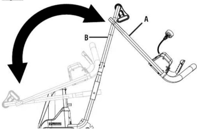
A - Knob (bouton, perilla)
B - Upper handle (poignée supérieure, mango superior)
C - Bolt (boulon, perno)
D - Groove (rainure, ranura)
Fig. 4

A - Upper handle (poignée supérieure, mango superior)
B - Lower handle (poignée inférieure, mango inferior)
C - Switch trigger cable (câble decommutateur, cable del interruptor)
Fig. 5
A - Upper handle (poignée supérieure, mango superior)
B - Lower handle (poignée inférieure, mango inferior)
Fig. 6
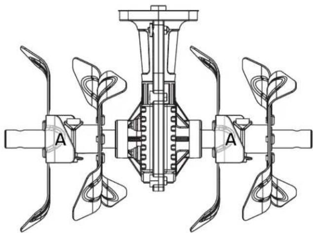
VIEW FROM THE FRONT
(VUE DE FACE, VISTA DESDE EL FRENTE)
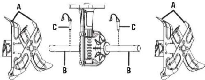
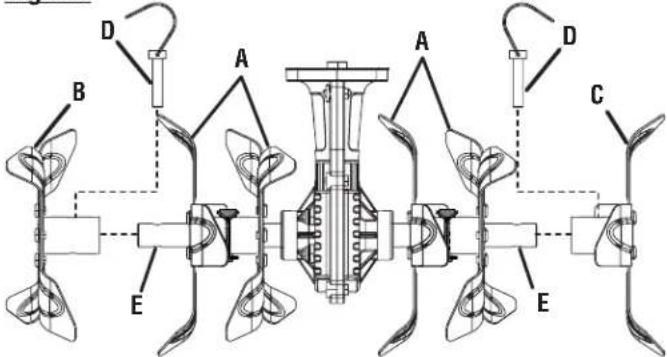
A - Inner tine assembly A (assemblages de dents intérieurs « A », conjuntos de púas internas “A”)
B - Tine shaft (arbre de dents, eje de las púas)
C - Lock pin (goupille de verrouillage, pasador de fijación)
Fig. 7
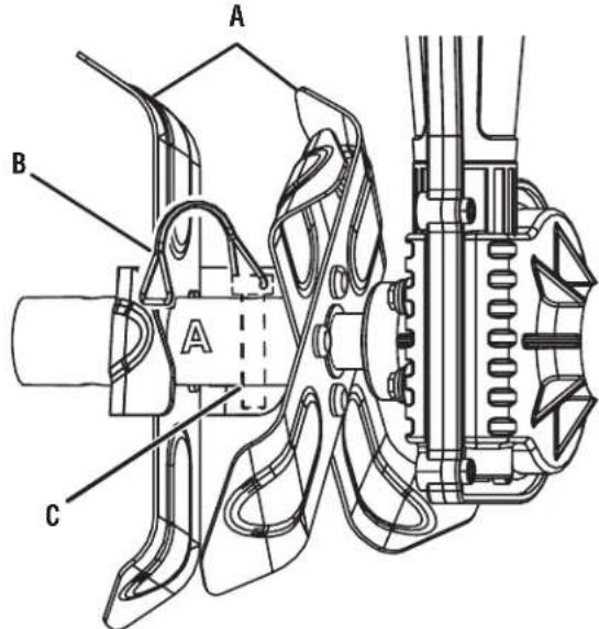
A - Inner tine assembly A (assemblages de dents intérieurs « A », conjuntos de púas internas “A”)
B - Band (bande, banda)
C - Lock pin (goupille de verrouillage, pasador de fijación)
Fig. 8
VIEW FROM THE FRONT
(VUE DE FACE, VISTA DESDE EL FRENTE)
natural_image
Technical line drawing of a mechanical component with three propellers and central shaft (no text or symbols)Fig. 9
VIEW FROM THE FRONT
(VUE DE FACE, VISTA DESDE EL FRENTE)
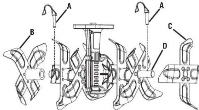
Fig. 11
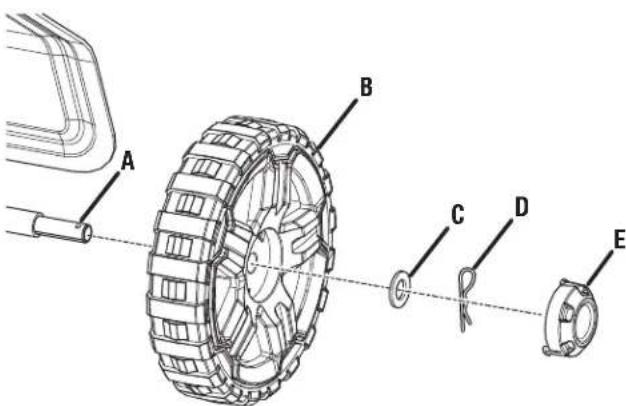
A - Axle (essieu, eje)
B - Wheel (roue, rueda)
C - Washer (rondelle, arandela)
D - Hitch pin (axe de blocage, pasador del enganche)
E - End cap (capuchon d'extrémité, tapa extremo)
Fig. 12
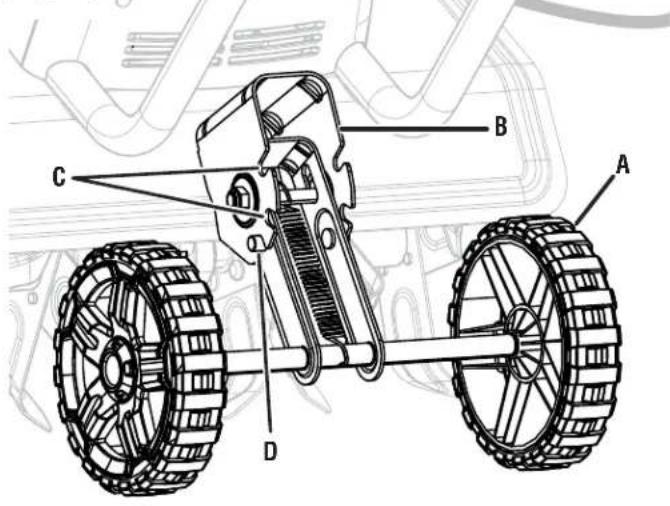
A - Wheel assembly (ensemble de roues, conjunto de rueda)
B - Bracket (support, soporte)
C - Notch (encoche, muesca)
D - Tab (ergot, orejeta)
natural_image
Technical line drawing of a mechanical tiller with a flanged blade and stator (no text or symbols)natural_image
Technical line drawing of a mechanical tiller with a wheel and blade assembly (no text or symbols)natural_image
Technical line drawing of a mechanical tiller with a flanged blade and rotor (no text or symbols)Fig. 16
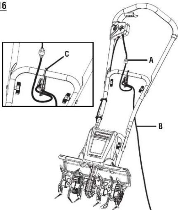
A - Lock-out button (bouton de verrouillage, botón de seguro)
B - Switch trigger (gâchette, gatillo del interruptor)
Fig. 17
REGULAR TINE PATTERN / DISPOSITION NORMALE DES LAMES DENTÉES / PATRÓN DE ASPAS REGULAR
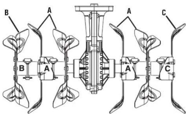
A - Inner tine assembly A (assemblages de dents intérieurs « A », conjuntos de púas internas “A”)
B - Outer tine B (dent extérieure B, púa exterior B)
C - Outer tine C (dent extérieure C, púa exterior C)
Fig. 18
A - Inner tine assembly A (assemblages de dents intérieurs « A », conjuntos de púas internas “A”)
B - Outer tine B (dent extérieure B, púa exterior B)
C - Outer tine C (dent extérieure C, púa exterior C)
A - Inner tine assembly A (assemblages de dents intérieurs « A », conjuntos de púas internas “A”)
IMPORTANT SAFETY INSTRUCTIONS

WARNING:
READ AND UNDERSTAND ALL INSTRUCTIONS.
Failure to follow all instructions listed below and on the machine may result in electric shock, fire, and/or serious personal injury.
- Know your cultivator. Read operator's manual carefully. Learn its applications and limitations, as well as the specific potential hazards related to this cultivator. Know how to stop the unit and disengage the controls quickly. Following this rule will reduce the risk of electric shock, fire, or serious injury.
■ Do not permit children to use cultivator. It is not a toy. Do not allow uninstructed adults to use this machine.
■ Powered walk-behind cultivator work is strenuous. You must be in good physical condition and mentally alert. If you have any condition that might be aggravated by strenuous work, check with your doctor before operating a powered walk-behind cultivator.
■ Use only accessories that are recommended by the manufacturer for your model described in this manual. Accessories that may be suitable for one cultivator may create a risk of injury when used on another cultivator. Use only as described in this manual.
■ Do not put any object into openings. Do not use with any opening blocked; keep free of dust, lint, hair, and anything that may reduce air flow. - Keep hair, loose clothing, fingers, and all parts of body away from openings and moving parts.
- Avoid Dangerous Environment - Don’t use appliances in damp or wet locations.
■ Do not operate in poor lighting.
To reduce the risk of electric shock, this product has a polarized plug (one blade is wider than the other) and will require the use of a polarized extension cord. The plug will fit into a polarized extension cord only one way. If the plug does not fit fully into the extension cord, reverse the plug. If the plug still does not fit, obtain a correct polarized extension cord. A polarized extension cord will require the use of a polarized wall outlet. This plug will fit into the polarized wall outlet only one way. If the plug does not fit fully into the wall outlet, reverse the plug. If the plug still does not fit, contact a qualified electrician to install the proper wall outlet. Do not change the equipment plug, extension cord receptacle, or extension cord plug in any way.
■ Avoid body contact with grounded surfaces such as pipes, radiators, ranges, and refrigerators. There is an increased risk of electric shock if your body is grounded.
■ Make sure your extension cord is in good condition. When using an extension cord, be sure to use one heavy enough to carry the current your product will draw. A wire gauge size (A.W.G.) of at least 14 is recommended for an extension cord 50 feet or less in length. If in doubt, use the next heavier gauge. The smaller the gauge number, the heavier the cord. An undersized cord will cause a drop in line voltage resulting in loss of power and overheating.
■ WARNING: Use outdoor extension cords marked SW-A, SOW-A, STW-A, STOW-A, SJW-A, SJTW-A, or SJTOW-A. These cords are rated for outdoor use and reduce the risk of electric shock.
■ Ground Fault Circuit Interrupter (GFCI) protection should be provided on the circuit(s) or outlet(s) to be used for the product. Receptacles are available having built-in GFCI protection and may be used for this measure of safety.
■ This product is designed with a cord retainer that prevents the extension cord from being pulled loose while using.
If cord is damaged in any manner while plugged in, pull extension cord from wall receptacle. Replace damaged cords immediately. Damaged cords increase the risk of electric shock.
- Don't Abuse Cord — Never carry cultivator by cord or yank it to disconnect from receptacle. Keep cord from heat, oil, sharp edges, and rotating parts.
- Keep hands away from moving parts.
- Never pick up or carry the cultivator while the tines are turning or the motor is running. Don't grasp the exposed cutting blades or cutting edges when picking up or holding the appliance.
- Avoid Unintentional Starting – Do not carry plugged in appliance with finger on trigger. Be sure the switch trigger is not engaged before plugging in.
- Do not use tool if switch trigger does not turn it on or off. Any tool that cannot be controlled with the switch trigger is dangerous and must be repaired.
- Do not operate cultivators in explosive atmospheres, such as in the presence of flammable liquids, gases, or dust. Cultivators create sparks which may ignite the dust or fumes.
- Keep bystanders, children, and visitors at least 100 ft. away while operating a cultivator. Distractions can cause you to lose control.
■ Start the cultivator carefully according to instructions from a normal operating position and with feet well away from the tines.
If appliance is not working as it should, has been dropped, damaged, left outdoors, or dropped into water, return it to a service center.
IMPORTANT SAFETY INSTRUCTIONS
■ Stay alert, watch what you are doing and use common sense when operating a power cultivator. Do not use cultivator while tired, upset, ill, or under the influence of drugs, alcohol, or medication. A moment of inattention while operating cultivators may result in serious personal injury.
■ Use safety equipment. Always wear eye protection. Dust mask, non-skid safety shoes, hard hat, or hearing protection must be used for appropriate conditions.
■ Dress properly — Do not wear loose clothing, scarves, or jewelry. They can be caught in moving parts.
■ Use of rubber gloves and substantial footwear is recommended when working outdoors.
- Secure long hair so it is above shoulder level to prevent entanglement in any moving parts.
- Check for misalignment or binding of moving parts, breakage of parts, and any other condition that may affect the cultivator's operation. If damaged, have the cultivator serviced before using. Many accidents are caused by poorly maintained cultivators.
- Keep the cultivator and its handle dry, clean, and free from oil and grease. Always use a clean cloth when cleaning. Never use brake fluids, gasoline, petroleum-based products, or any strong solvents to clean your cultivator. Following this rule will reduce the risk of loss of control and deterioration of the enclosure plastic.
■ Always wear safety glasses with side shields. Everyday glasses have only impact resistant lenses. They are NOT safety glasses. Following this rule will reduce the risk of eye injury.
■ Always wear eye protection with side shields marked to comply with ANSI Z87.1 along with hearing protection when operating this equipment. Following this rule will reduce the risk of serious personal injury.
■ Protect your lungs. Wear a face or dust mask if the operation is dusty. Following this rule will reduce the risk of serious personal injury.
- Don't expose cultivators to rain. Water entering a cultivator will increase the risk of electric shock.
■ Never spray water directly into the motor compartment of the cultivator.
■ Wear heavy long pants, long sleeves, boots, and gloves. Avoid loose garments or jewelry that could get caught in moving parts of the machine or its motor.
■ Wear rubber boots when operating the cultivator. Protective footwear will protect your feet and improve your footing on slippery surfaces. Do not go barefoot or wear sandals.
- Keep firm footing and balance. Do not overreach. Overreaching can result in loss of balance.
■ Store Idle Cultivators Indoors — When not in use, cultivator should be stored indoors in a dry, locked up place — unplugged and out of the reach of children.
■ Do not hang unit so that the switch trigger is depressed.
■ Cultivator service must be performed only by qualified repair personnel. Service or maintenance performed by unqualified personnel may result in a risk of injury.
■ When servicing a cultivator, use only identical replacement parts. Replace or repair damaged cords. Follow instructions in the Maintenance section of this manual. Use of unauthorized parts or failure to follow Maintenance instructions may create a risk of shock or injury.
- Check the work area before each use. Remove all objects such as rocks, broken glass, nails, wire, or string which can be thrown or become entangled in the machine.
■ For household use only.
■ Use the right appliance — Do not use the cultivator for any job except that for which it is intended.
■ Do not force the cultivator — It will do the job better and safer at the rate for which it was designed.
■ Do not use near underground electric cables, telephone lines, pipes, or hoses. If in doubt, contact your utility or telephone company to locate underground services.
■ Rotating tines can cause severe injury; do not allow hands, feet, or any other part of the body or clothing near the rotating tines or any other moving part. The tines begin to rotate once the lock-out button is depressed and switch trigger is pulled. The tines continue to rotate until the switch trigger is released.
■ Maintain a firm grip on both handles while cultivating. Use extreme caution when reversing or pulling the machine towards you. Never operate the equipment on a slope.
If the cultivator should start to vibrate abnormally or become noisy, stop the motor and check immediately for the cause. Abnormal noise is generally a warning of trouble.
- Keep all fasteners tight to be sure the cultivator is in safe working condition.
- Check that the lock pins are fully inserted into the tine shaft before each use.
■ Exercise extreme caution when crossing gravel surfaces. Stay alert for hidden hazards or traffic.
■ Be extremely careful when tilling in hard ground. The equipment may unexpectedly bounce upward or jump forward if the tines should strike buried obstacles such as large stones, roots, or stumps.
■ Do not overload the capacity of the machine by attempting to till too deep or at too fast a speed.
IMPORTANT SAFETY INSTRUCTIONS
■ If the cultivator strikes a foreign object, follow these steps:
- Release the switch trigger and wait until the unit comes to a complete stop.
- Disconnect the cultivator from the power supply.
- Thoroughly inspect the cultivator for any damage.
- Repair any damage before restarting and continuing to operate the cultivator.
- Do not lift up or hold the cultivator above the ground when operating, which can result in loss of control and possible serious personal injury. Only operate the cultivator in accordance with the operating instructions provided in this operator's manual.
- Keep guards in place and in working order. Never operate the machine without proper guards, plates, or other safety protective devices in place.
- Check Damaged Parts - Before further use of the appliance, a guard or other part that is damaged should be carefully checked to determine that it will operate properly and perform its intended function. Check for alignment of moving parts, binding of moving parts, breakage of parts, mounting, and any other condition that may affect its operation. A guard or other part that is damaged should be properly repaired or replaced by an authorized service center unless indicated elsewhere in this manual.
■ Disconnect the plug from power source when not in use, before servicing, and when changing accessories. - Maintain Appliance With Care - Keep cutting edge sharp and clean for best performance and to reduce the risk of injury. Follow instructions for lubricating and changing accessories. Inspect appliance cord periodically, and if damaged, have it repaired by an authorized service facility. Inspect extension cords periodically and replace if damaged. Keep handles dry, clean, and free from oil and grease.
■ Save these instructions. Refer to them frequently and use them to instruct others who may use this tool. If you loan someone this tool, loan them these instructions also.
SYMBOLS
| The following signal words and meanings are intended to explain the levels of risk associated with this product. SYMBOL SIGNAL MEANING | ||
 | DANGER: | Indicates a hazardous situation, which, if not avoided, will result in death or serious injury. |
 | WARNING: | Indicates a hazardous situation, which, if not avoided, could result in death or serious injury. |
 | CAUTION: | Indicates a hazardous situation, that, if not avoided, may result in minor or moderate injury. |
| NOTICE: | (Without Safety Alert Symbol) Indicates information considered important, but not related to a potential injury (e.g. messages relating to property damage). | |
| Some of the following symbols may be used on this product. Please study them and learn their meaning. Proper interpretation of these symbols will allow you to operate the product better and safer. SYMBOL NAME DESIGNATION/EXPLANATION | ||
 | Safety Alert Indicates a potentia | personal injury hazard. |
 | Read Operator's Manual | To reduce the risk of injury, user must read and understand operator's manual before using this product. |
 | Eye Protection | Always wear eye protection which is marked to comply with ANSI Z87.1 when operating this equipment. |
 | Wet Conditions Alert Do not expose plug to water or rain. | |
 | Keep Bystanders Away Keep all bystanders at least 50 ft. away. | |
 | Rotating Tines | Danger — Keep hands and feet away from rotating tines. Rotating tines will cause injury. |
| V Volts Voltage | ||
| A Amperes Current | ||
| Hz Hertz Frequency (cycles per second) | ||
| W | Watt | Power |
| hrs | Hours | Time |
| n_b | No Load Speed | Rotational speed, at no load |
| 回 | Class II Construction | Double-insulated construction |
| .../min | Per Minute | Revolutions, strokes, surface speed, orbits etc., per minute |
ELECTRICAL
DOUBLE INSULATION
Double insulation is a concept in safety in electric power tools, which eliminates the need for the usual three-wire grounded power cord. All exposed metal parts are isolated from the internal metal motor components with protecting insulation. Double insulated tools do not need to be grounded.

WARNING:
The double insulated system is intended to protect the user from shock resulting from a break in the tool's internal insulation. Observe all normal safety precautions to avoid electrical shock.
NOTE: Servicing of a tool with double insulation requires extreme care and knowledge of the system and should be performed only by a qualified service technician. For service, we suggest you return the tool to your nearest authorized service center for repair. Always use original factory replacement parts when servicing.
ELECTRICAL CONNECTION
This tool has a precision-built electric motor. It should be connected to a power supply that is nominal 120V/60Hz AC (typical U.S. household circuit). Do not operate this tool on direct current (DC). A substantial voltage drop will cause a loss of power and the motor will overheat. If your tool does not operate when plugged into an outlet, double-check the power supply.
GFCI
Ground Fault Circuit Interrupter (GFCI) protection should be provided on the circuit(s) or outlet(s) to be used for the product. Receptacles are available having built-in GFCI protection and may be used for this measure of safety.
EXTENSION CORDS
When using a power tool at a considerable distance from a power source, be sure to use an extension cord that has the capacity to handle the current the tool will draw. An undersized cord will cause a drop in line voltage, resulting in overheating and loss of power. Use the chart to determine the minimum wire size required in an extension cord. Only round jacketed cords listed by Underwriter's Laboratories (UL) should be used.
When working outdoors with a tool, use an extension cord that is designed for outside use. This type of cord is designated with "WA" or "W" on the cord's jacket.
Before using any extension cord, inspect it for loose or exposed wires and cut or worn insulation.
**Ampere rating (on tool data plate)
0-2.0 2.1-3.4 3.5-5.0 5.1-7.0 7.1-12.0 12.1-16.0
Cord Length Wire Size (A.W.G.)
| 25' | 16 | 16 | 16 | 16 | 14 | 14 |
| 50' | 16 | 16 | 16 | 14 | 14 | 12 |
| 100' | 16 | 16 | 14 | 12 | 10 | — |
**Used on 12 gauge - 20 amp circuit.
NOTE: AWG = American Wire Gauge

WARNING:
Keep the extension cord clear of the working area. Position the cord so that it will not get caught on lumber, tools, or other obstructions while you are working with a power tool. Failure to do so can result in serious personal injury.

WARNING:
Check extension cords before each use. If damaged replace immediately. Never use tool with a damaged cord since touching the damaged area could cause electrical shock resulting in serious injury.
FEATURES
PRODUCT SPECIFICATIONS
Input ...... nominal 120V/60Hz AC only, 13.5 Amps
Number of Tines....6
Cultivating Depth....8 in.
Cultivating Width 16 in.
KNOW YOUR CULTIVATOR
See Figure 1.
The safe use of this product requires an understanding of the information on the product and in this operator's manual as well as a knowledge of the project you are attempting. Before use of this product, familiarize yourself with all operating features and safety rules.
LOCK-OUT BUTTON
The lock-out button prevents accidental starting of the cultivator.
SWITCH TRIGGER
The switch trigger starts and stops the rotation of the tines.
ASSEMBLY
UNPACKING
This product requires assembly.
- Carefully remove the product and any accessories from the box. Make sure that all items listed in the packing list are included.

WARNING:
Do not use this product if any parts on the packing list are already assembled to your product when you unpack it. Parts on this list are not assembled to the product by the manufacturer and require customer installation. Use of a product that may have been improperly assembled could result in serious personal injury.
■ Inspect the product carefully to make sure no breakage or damage occurred during shipping.
■ Do not discard the packing material until you have carefully inspected and satisfactorily operated the product.
■ If any parts are damaged or missing, please call 1-800-860-4050 for assistance.
PACKING LIST
Cultivator
Upper Handle
Lower Handle
Bolts (4)
Knobs (4)
Outer Tines (2)
PACKING LIST (continued)
Inner Tine Assemblies (2)
Lock Pins (4)
Wheels (2)
Washers (2)
Hitch Pins (2)
End Caps (2)
Operator's Manual

WARNING:
If any parts are damaged or missing, do not operate this product until the parts are replaced. Use of this product with damaged or missing parts could result in serious personal injury.

WARNING:
Do not attempt to modify this product or create accessories not recommended for use with this product. Any such alteration or modification is misuse and could result in a hazardous condition leading to possible serious personal injury.

WARNING:
Do not connect to power supply until assembly is complete. Failure to comply could result in accidental starting and possible serious personal injury.
ASSEMBLY
INSTALLING THE HANDLE ASSEMBLY
See Figures 2 - 3.
■ Place the lower handle onto the bar on the cultivator.
NOTE: The bar should fit inside the grooves in the lower handle.
■ Align the holes in the lower handle with the holes in the bar, and secure using bolts and knobs. Tighten knobs securely.
■ Place the upper handle onto the lower handle.
NOTE: The lower handle should fit inside the grooves in the upper handle.
■ Align the holes in the lower handle with the holes in the upper handle, and secure using bolts and knobs. Tighten knobs securely.
FOLDING/UNFOLDING THE HANDLE ASSEMBLY
See Figures 4 - 5.
To fold handle assembly:
■ Loosen the knobs on the upper handle.
■ Fold the upper handle down and back onto the lower handle.
NOTE: Do not use force. If there is binding, continue to loosen the knobs. Do not allow the switch trigger cable to become pinched when lowering the handle.
■ Loosen the knobs on the lower handle.
■ Push the upper and lower handles forward and down onto the cultivator.
To unfold handle assembly:
■ Pull the lower handle up and back until it is aligned with the bar on the cultivator.
NOTE: The bar should fit inside the grooves in the lower handle.
■ Tighten the knobs on the lower handle, to secure it in place.
■ Pull the upper handle up and forward until it is aligned with the lower handle.
NOTE: The lower handle should fit inside the grooves in the upper handle.
■ Tighten the knobs on the upper handle, to secure it in place.

WARNING:
Be certain the knobs are fully tightened before operating equipment; check them periodically for tightness during use to avoid serious personal injury.
INSTALLING THE TINES
See Figures 6 - 10.
The inner tine assemblies are marked "A". The right outer tine is marked "C" and the left outer tine is marked "B". For correct operation of the unit, the tines must be installed in the correct position.
■ Place the inner tine assemblies on the tine shaft as shown.
■ Rotate the tine assemblies until the holes in the assemblies are aligned with the holes in the tine shaft.
NOTE: If the holes do not align, the tine assemblies may be installed on the wrong sides. Reverse the position of the tine assemblies and check for hole alignment. When installed correctly, the "A" on the right inner tine assembly should be closer to the gear box than the "A" on the left inner tine assembly.
■ Insert lock pins through the holes in the tine assemblies and the shaft.
■ Pull the band on each lock pin around the tine shaft and connect them to the bottom of each pin.
- Place the outer tine marked “C” on the right side of the tine shaft and the outer tine marked “B” on the left side of the shaft.
■ Rotate the outer tines until the holes in the tines are aligned with the holes in the tine shaft.
■ Install lock pins and secure the outer tines in place.
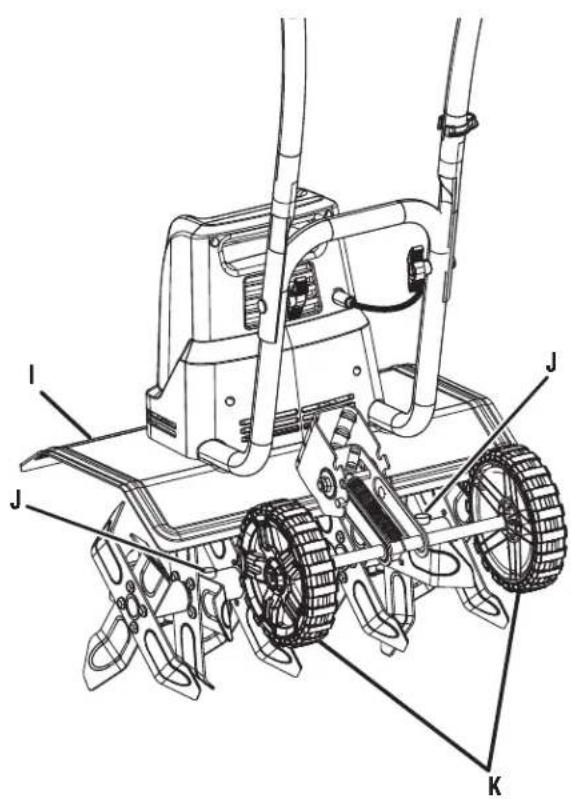
INSTALLING THE WHEELS
See Figure 11.
Wheels are provided to assist in moving the unit to and from the work area. To install:
■ Slide a wheel onto the axle.
■ Slide a washer onto the axle until it touches the wheel.
■ Insert a hitch pin to secure.
NOTE: The hitch pin should be pushed into the axle until the center of the pin rests on top of the axle.
■ Push the end cap into the center of the wheel until it snaps into place.
■ Repeat with the second wheel.
ASSEMBLY
CHANGING WHEEL POSITIONS
See Figures 12 - 15.
The wheel position of the unit is adjustable. Adjust the position of the wheels by placing the tabs on the wheel assembly into different sets of notches on the bracket.

CAUTION:
The wheel assembly is spring loaded. Be careful to avoid pinching your fingers or hands when adjusting the wheel position.
■ From the rear of the cultivator, pull the wheel assembly away from the bracket.
NOTE: The spring loaded wheel assembly will snap forward if released.
■ Slowly bring the wheel assembly toward the bracket and seat the tabs on the wheel assembly into a set of notches on the bracket.
- Place the wheel assembly into the lowest set of notches (position A) to transport the cultivator or for shallow cultivating.
- Place the wheel assembly into the middle set of notches (position B) for general cultivating with moderate surface penetration.
- Place the wheel assembly into the top set of notches (position C) to allow deep penetration of the tine blades into the cultivating surface.
OPERATION

WARNING:
Do not allow familiarity with products to make you careless. Remember that a careless fraction of a second is sufficient to inflict serious injury.

WARNING:
Always wear eye protection with side shields marked to comply with ANSI Z87.1. Failure to do so could result in objects being thrown into your eyes resulting in possible serious injury.

WARNING:
Do not use any attachments or accessories not recommended by the manufacturer of this product. The use of attachments or accessories not recommended can result in serious personal injury.
NOTICE:
Before each use, inspect the entire product for damaged, missing, or loose parts such as screws, nuts, bolts, caps, etc. Tighten securely all fasteners and caps and do not operate this product until all missing or damaged parts are replaced. Please contact customer service or an authorized service center for assistance.
APPLICATIONS
You may use this product for the purpose listed below:
■ Breaking up garden soil to prepare seed bed for planting
■ Shallow cultivating to remove weeds
CONNECTING TO POWER SUPPLY
See Figure 16.
This product is designed with a cord retainer that prevents the extension cord from being pulled loose while using.
■ Form a loop with the end of the extension cord.
■ Insert loop portion of extension cord through opening in the bottom of the cord retainer and place over hook.
■ Slowly pull loop against cord retainer until the slack is removed.
- Plug product into extension cord.
NOTE: Failure to remove all excess cord slack from extension cord retainer could result in plug loosening from receptacle.

WARNING:
Always disconnect cultivator from power supply when you are assembling parts, making adjustments, cleaning, or when not in use. This will prevent accidental starting that could cause serious personal injury.
STARTING/STOPPING THE CULTIVATOR
See Figure 17.
To start the motor:
■ Connect the cultivator to power supply.
NOTICE:
Always secure extension cord to unit by using cord retainer. Failure to use cord retainer may result in damage to the unit and/or extension cord.
OPERATION
■ Place your thumb on the lock-out button.
■ Pull the switch trigger toward the handle.
■ Release the lock-out button.
To stop the motor:
■ Release the switch trigger.
PREPARING THE SEED BED
See Figure 17.

WARNING:
Do not allow hands, feet, or any other part of the body or clothing near the rotating tines or any other moving part. The tines begin to rotate once the lock-out button is depressed and switch trigger is pulled. The tines continue to rotate until the switch trigger is released. Failure to avoid contact could cause serious personal injury.

WARNING:
To avoid personal injury, never carry the cultivator while the motor is running. Move the cultivator to the work area before starting the motor.

WARNING:
After extended periods of use, the cultivator gearbox may become hot. To avoid burns, do not touch the gearbox until it has had time to cool down.

WARNING:
Always hold the cultivator away from the body keeping clearance between the body and the cultivator. Any contact with the tines while operating can result in serious personal injury.
The cultivator can be used to break up garden soil and prepare a seedbed for planting. Plan ahead to leave enough room between the seed rows to allow for machine cultivating after the plants have grown.
■ With the wheel assembly installed in position A as described earlier, roll the machine to the work area.
■ Adjust the position of the wheel assembly for shallow, moderate, or deep cultivation (refer to Changing Wheel Positions).
NOTE: Based on the type of soil being cultivated and soil conditions at the time, the appropriate position of the wheel assembly will vary.
- Plug the unit into an approved outdoor extension cord.
■ Route the extension cord through the cord retainer.
■ Stand behind the unit with the tines on the ground and the work area clean and free of obstructions.
■ Depress the lock-out button.
■ Pull the switch trigger toward the handle to begin tine rotation.
NOTE: The rotating tines help to pull the machine forward, so use slower speeds and a shallow depth setting when learning to use the unit and when cultivating on rough or uneven ground.
NOTE: Several passes over the same path may be required to reach the desired depth. Do not try to dig too deeply in the first pass. If the machine jumps or bucks, allow the unit to move forward at a slightly faster rate or adjust the position of the wheel assembly.
To dig more deeply, tilt the handle bar upward (lowering the tines). Apply downward pressure on the handle for more shallow cultivating (raising the tines).
If the machine stays and digs in one spot, try rocking the unit from side to side to start it moving forward again.
If the soil is very hard, water a few days before cultivating.
Avoid working the soil when soggy or wet. Wait a day or two after heavy rain for the ground to dry.
TINE PATTERNS
See Figures 18 - 20.
For most applications, the regular tine pattern will work best. This is the pattern set by the factory.
When tilling in confined areas or rows, remove the outer tines to create a narrow tine pattern.
NOTE: Do not force the tines on or off the shaft. If you experience difficulties when removing the tines, apply some penetrating lubricant on the shaft. When reinstalling the tines, make sure to clean and lubricate the shaft and the tine hubs.
OPERATION
To change to a narrow tine pattern:
■ Remove the lock pins securing the outer tines from each side of the cultivator.
NOTE: The right outer tine is marked "C" and the left outer tine is marked "B".
■ Remove the outer tines.
- When work is complete, place the outer tine marked "C" on the right side of the tine shaft and the outer tine marked "B" on the left side of the shaft.
MAINTENANCE

WARNING:
Before inspecting, cleaning or servicing the unit, stop the motor, wait for all moving parts to stop, and disconnect from power supply. Failure to follow these instructions can result in serious personal injury or property damage.

WARNING:
Always wear eye protection with side shields marked to comply with ANSI Z87.1. Failure to do so could result in objects being thrown into your eyes resulting in possible serious injury.

WARNING:
When servicing, use only authorized replacement parts. Use of any other parts can create a hazard or cause product damage.
NOTICE:
Periodically inspect the entire product for damaged, missing, or loose parts such as screws, nuts, bolts, caps, etc. Tighten securely all fasteners and caps and do not operate this product until all missing or damaged parts are replaced. Please contact customer service or an authorized service center for assistance.
GENERAL MAINTENANCE
Avoid using solvents when cleaning plastic parts. Most plastics are susceptible to damage from various types of commercial solvents and may be damaged by their use. Use clean cloths to remove dirt, dust, oil, grease, etc.

WARNING:
Do not at any time let brake fluids, gasoline, petroleum-based products, penetrating oils, etc., come in contact with plastic parts. Chemicals can damage, weaken, or destroy plastic which can result in serious personal injury.
LUBRICATION
All of the bearings in this product are lubricated with a sufficient amount of high grade lubricant for the life of the unit under normal operating conditions. Therefore, no further bearing lubrication is required.
STORING THE CULTIVATOR
■ Clean dirt, grass, and other materials from the entire unit.
■ Wipe the tines with oil or spray them with silicone lubricant to prevent rusting.
■ Oil the switch trigger cable and all visible moving parts. Do not remove the motor cover.
■ Order new parts to replace any that are badly worn or broken.
■ Store in an upright position in a clean, dry place. Store with the handles in the extended position, or loosen knobs and fold handles down. Do not allow switch trigger cable to become pinched when lowering the handle.
TROUBLESHOOTING
IF THESE SOLUTIONS DO NOT SOLVE THE PROBLEM CONTACT YOUR AUTHORIZED SERVICE DEALER.
| PROBLEM POSSIBLE | CAUSE SOLUTION | |
| Motor fails to start when switch trigger is depressed. | Power cord is not plugged in or connection is loose.Household circuit breaker is tripped. | Plug in the power cord.Check circuit breaker. |
| Motor runs but tines do not move. Gear | train failure. Take unit to authorized service center. | |

MAKE THE MOST OF YOUR PURCHASE!
Go to http://register.ryobitools.com and register your new tool on-line.
Your product has been fully tested prior to shipment to ensure your complete satisfaction.
For any questions about operating or maintaining your product, call the RYOBI Help Line!
This product has a Five-year Limited Warranty for personal, family, or household use (90 days for business or commercial use). For warranty details, visit www.ryobitools.com or call (toll free) 1-800-860-4050.
INSTRUCTIONS IMPORTANTES CONCERNANT LA SÉCURITÉ

AVERTISSEMENT:
- PARTS AND SERVICE: Prior to requesting service or purchasing replacement parts, please obtain your item, manufacturing, and serial numbers from the product data plate.
ITEM NO.
MANUFACTURING NO.
SERIAL NO.
HOW TO OBTAIN REPLACEMENT PARTS: Replacement parts can be purchased online at www.ryobitools.com or by calling 1-800-860-4050. Replacement parts can also be obtained at one of our service centers.
HOW TO LOCATE A SERVICE CENTER: Service centers can be located online at www.ryobitools.com or by calling 1-800-860-4050.
HOW TO OBTAIN CUSTOMER OR TECHNICAL SUPPORT: To obtain customer or technical support please contact us at 1-800-860-4050.
RYOBI is a registered trademark of Ryobi Limited and is used pursuant to a license granted by Ryobi Limited.