
DW841 - Grinder DEWALT - Free user manual and instructions
Find the device manual for free DW841 DEWALT in PDF.


User questions about DW841 DEWALT
0 question about this device. Answer the ones you know or ask your own.
Ask a new question about this device
Download the instructions for your Grinder in PDF format for free! Find your manual DW841 - DEWALT and take your electronic device back in hand. On this page are published all the documents necessary for the use of your device. DW841 by DEWALT.
USER MANUAL DW841 DEWALT
text_image
Technical diagram of a power tool with numbered parts labeled 1 to 5A
DW830
text_image
8 6 7B1
DW840
DW841
text_image
Technical diagram of a mechanical assembly with numbered components and directional arrows indicating motion or assembly steps.B2
text_image
DW830 9 C1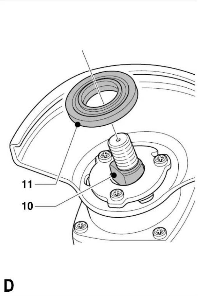
text_image
11 10 D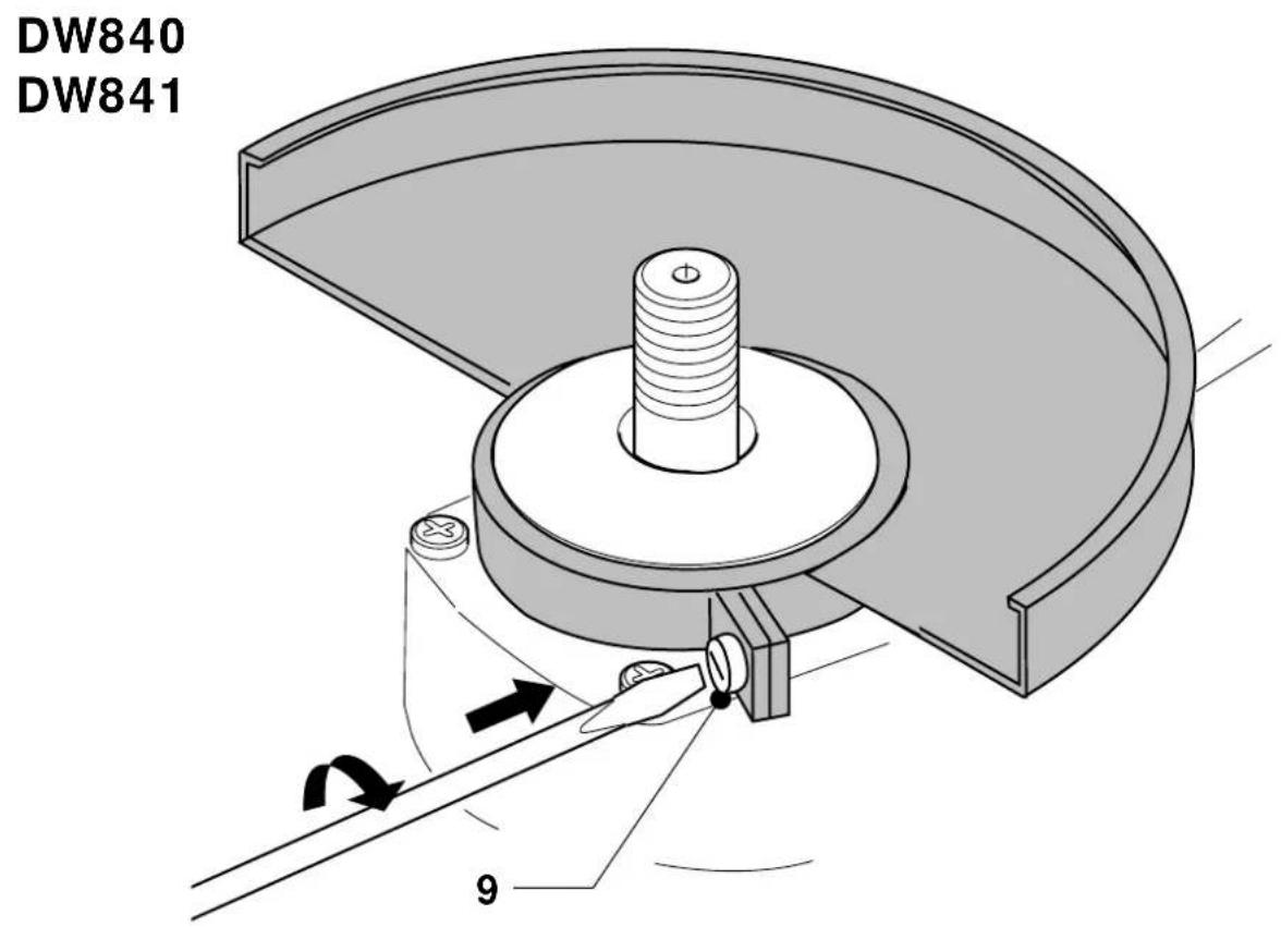
text_image
DW840 DW841 9C2
text_image
513 12E
text_image
14 2F
text_image
Technical diagram of a hairdryer with labeled parts 1 and 2G
VINKELSLIBER DW830/DW840/DW841
Tillykke!
WINKELSCHLEIFER DW830/DW840/DW841
MEDIUM ANGLE GRINDER DW830/DW840/DW841
Congratulations!
You have chosen a DEWALT Power Tool. Years of experience, thorough product development and innovation make DEWALT one of the most reliable partners for professional Power Tool users.
Table of contents
| Technical data en - 1 |
| EC-Declaration of conformity en - 2 |
| Safety instructions en - 2 |
| Package contents en - 3 |
| Description en - 4 |
| Electrical safety en - 4 |
| Mains plug replacement (U.K. & Ireland only) en - 4 |
| Using an extension cable en - 4 |
| Assembly and adjustment en - 5 |
| Instructions for use en - 5 |
| Maintenance en - 6 |
| Guarantee en - 6 |
Technical data
| DW830 DW840 DW841 | ||||
| Voltage V 230 | 230 | 230 | ||
| (U.K. & Ireland only) | V 115 | 115 | 115 | |
| Power input | W 1,400 | 1,800 | 2,000 | |
| No load speed | min^-1 10,000 | 8,000 | 8,000 | |
| Wheel diameter | mm 125 | 180 | 180 | |
| Max. wheel width | mm 6.5 | 7.0 | 7.0 | |
| Spindle | M14 | M14 | M14 | |
| Weight | kg 2.7 | 3.2 | 3.3 | |
| Fuses: | ||||
| Europe | 230 V tools | 10 Amperes, mains | ||
| U.K. & Ireland | 230 V tools | 13 Amperes, in plugs | ||
The following symbols are used throughout this manual:

Denotes risk of personal injury, loss of life or damage to the tool in case of non-observance of the instructions in this manual.

Denotes risk of electric shock.
EC-Declaration of conformity
CE
DW830/DW841
DEWALT declares that these power tools have been designed in compliance with: 98/37/EEC, 89/336/EEC, 73/23/EEC, EN 50144, EN 55014-2, EN 55014, EN 61000-3-2 & EN 61000-3-3.
DW840
DEWALT declares that these power tools have been designed in compliance with: 98/37/EEC, 89/336/EEC, 73/23/EEC, EN 50144, EN 55014-2, EN 55014, EN 61000-3-2 & EN 61000-3-11.
For more information, please contact DEWALT at the address below, or refer to the back of the manual.
Level of sound pressure according to 86/188/EEC & 98/37/EEC, measured according to EN 50144:
| DW830 DW840 DW841 | |
| L_pA | (sound pressure) dB(A)^* 90 90 90 |
| L_WA | (acoustic power) dB(A) 103 103 103 |
* at the operator's ear

Take appropriate measures for the protection of hearing if the sound pressure of 85 dB(A) is exceeded.
Weighted root mean square acceleration value according to EN 50144:
| DW830 | DW840 | DW841 | |
| 5 m/s2 | 5 m/s2 | 5 m/s2 |
Director Engineering & Product Development Horst Großmann
X. fopmann
When using Power Tools, always observe the safety regulations applicable in your country to reduce the risk of fire, electric shock and personal injury. Read the following safety instructions before attempting to operate this product. Keep these instructions in a safe place!
General
1 Keep work area clean Cluttered areas and benches can cause accidents.
2 Consider work area environment
Do not expose Power Tools to humidity. Keep work area well lit. Do not use Power Tools in the presence of inflammable liquids or gases.
3 Guard against electric shock
Prevent body contact with earthed surfaces (e.g. pipes, radiators, cookers and refrigerators). For use under extreme conditions (e.g. high humidity, when metal swarf is being produced, etc.) electric safety can be improved by inserting an isolating transformer or a (FI) earth-leakage circuit-breaker.
4 Keep children away
Do not let children come into contact with the tool or extension cord. Supervision is required for those under 16 years of age.
5 Extension cords for outdoor use
When the tool is used outdoors, always use extension cords intended for outdoor use and marked accordingly.
6 Store idle tools
When not in use, Power Tools must be stored in a dry place and locked up securely, out of reach of children.
7 Dress properly
Do not wear loose clothing or jewellery. They can be caught in moving parts. Preferably wear rubber gloves and non-slip footwear when working outdoors. Wear protective hair covering to keep long hair out of the way.
8 Wear safety goggles
Also use a face or dust mask in case the operations produce dust or flying particles.
9 Beware of maximum sound pressure
Take appropriate measures for the protection of hearing if the sound pressure of 85 dB(A) is exceeded.
10 Secure workpiece
Use clamps or a vice to hold the workpiece. It is safer and it frees both hands to operate the tool.
11 Do not overreach
Keep proper footing and balance at all times.
12 Avoid unintentional starting
Do not carry the plugged-in tool with a finger on the switch. Be sure that the switch is released when plugging in.
13 Stay alert
Watch what you are doing. Use common sense. Do not operate the tool when you are tired.
14 Disconnect tool
Shut off power and wait for the tool to come to a complete standstill before leaving it unattended. Unplug the tool when not in use, before servicing or changing accessories.
15 Remove adjusting keys and wrenches
Always check that adjusting keys and wrenches are removed from the tool before operating the tool.
16 Use appropriate tool
The intended use is laid down in this instruction manual. Do not force small tools or attachments to do the job of a heavy-duty tool. The tool will do the job better and safer at the rate for which it was intended.
Warning! The use of any accessory or attachment or performance of any operation with this tool, other than those recommended in this instruction manual may present a risk of personal injury.
17 Do not abuse cord
Never carry the tool by its cord or pull it to disconnect from the socket. Keep the cord away from heat, oil and sharp edges.
18 Maintain tools with care
Keep the tools in good condition and clean for better and safer performance. Follow the instructions for maintenance and changing accessories. Inspect the tool cords at regular intervals and, if damaged, have them repaired by an authorized DEWALT repair agent. Inspect the extension cords periodically and replace them if damaged. Keep all controls dry, clean and free from oil and grease.
19 Check for damaged parts
Before using the tool, carefully check it for damage to ensure that it will operate properly and perform its intended function.
Check for misalignment and seizure of moving parts, breakage of parts and any other conditions that may affect its operation.
Have damaged guards or other defective parts repaired or replaced as instructed. Do not use the tool if the switch is defective. Have the switch replaced by an authorized DEWALT repair agent.
20 Have your tool repaired by an authorized DEWALT repair agent
This Power Tool is in accordance with the relevant safety regulations. To avoid danger, electric appliances must only be repaired by qualified technicians.
Additional safety rules for angle grinders
- Your angle grinder has been designed for grinding and cutting masonry and steel.

Do not cut or grind light metal with a magnesium content exceeding 80% since this type of metal is flammable.
- Do not use any accessories other than fibre reinforced grinding wheels and cutting disks.
- Use the grinding wheels and cutting disks recommended by the manufacturer only.
- The no-load speed of the grinding wheel or cutting disk must not exceed the value printed on the nameplate (instruction sheet).
- Do not cut workpieces requiring a maximum depth of cut exceeding that of the cutting disk.
Package contents
The package contains:
1 Angle grinder
1 Guard
1 Side handle
1 Flange set
1 Two-pin spanner
1 Instruction manual
1 Exploded drawing
- Check for damage to the tool, parts or accessories which may have occurred during transport.
• Take the time to thoroughly read and understand this manual prior to operation.
Description (fig. A)
Your angle grinder has been designed for professional grinding and cutting applications.
1 ON/OFF-switch
2 Lock-on button / lock-off button (UK only)
3 Side handle
4 Guard
5 Spindle lock
DW841 - Soft start feature
The soft start feature allows a slow speed build-up to avoid an initial jerk when starting. This feature is particularly useful when working in confined spaces.
DW841 - Constant speed control feature
The constant speed control feature maintains tool speed under load to assure optimum efficiency and productivity. It also functions as an overload feature.
DW841 - Overload protection
The unit will automatically stop drawing current if the motor is being overloaded. For optimum efficiency and to avoid damaging the motor, do not overload the motor for long periods.
Electrical safety
The electric motor has been designed for one voltage only. Always check that the power supply corresponds to the voltage on the rating plate.

Your DEWALT tool is double insulated in accordance with EN 50144; therefore no earth wire is required.
Mains plug replacement (U.K. & Ireland only)
- Should your mains plug need replacing and you are competent to do this, proceed as instructed below. If you are in doubt, contact an authorized DEWALT repair agent or a qualified electrician.
- Disconnect the plug from the supply.
- Cut off the plug and dispose of it safely; a plug with bared copper conductors is dangerous if engaged in a live socket outlet.
- Only fit 13 Amperes BS1363A approved plugs fitted with the correctly rated fuse (1).
- The cable wire colours, or a letter, will be marked at the connection points of most good quality plugs.
Attach the wires to their respective points in the plug (see below). Brown is for Live (L) (2) and Blue is for Neutral (N) (4).
- Before replacing the top cover of the mains plug ensure that the cable restraint (3) is holding the outer sheath of the cable firmly and that the two leads are correctly fixed at the terminal screws.
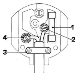
text_image
Technical diagram of a mechanical or electrical component with numbered parts labeled 1, 2, 3, and 4.
Never use a light socket.
Never connect the live (L) or neutral (N) wires to the earth pin marked E or ± .
For 115 V units with a power rating exceeding 1500 W, we recommend to fit a plug to BS4343 standard.
Using an extension cable
If an extension cable is required, use an approved extension cable suitable for the power input of this tool (see technical data). The minimum conductor size is 1.5 mm^2 . When using a cable reel, always unwind the cable completely.
Also refer to the table below.
| Conductor size (mm2) Cable rating (Amperes) | |||||||
| 0.75 6 | |||||||
| 1.00 10 | |||||||
| 1.50 15 | |||||||
| 2.50 20 | |||||||
| 4.00 25 | |||||||
| Cable length (m) | |||||||
| 7.5 15 25 30 45 60 | |||||||
| Voltage Amperes Cable rating (Amperes) | |||||||
| 115 0 - 2.0 6 6 | 6 6 | 6 10 | |||||
| 2.1 - 3.4 6 6 | 6 6 15 15 | ||||||
| 3.5 - 5.0 6 6 | 10 15 | 20 20 | |||||
| 5.1 - 7.0 | 10 10 15 20 20 25 | ||||||
| 7.1 - 12.0 | 15 15 20 25 25 | - | |||||
| 12.1 - 20.0 | 20 | 20 | 25 | - | - | - | |
| 230 0 - 2.0 6 6 6 6 6 6 |
| 2.1 - 3.4 6 6 6 6 6 6 |
| 3.5 - 5.0 6 6 6 6 10 15 |
| 5.1 - 7.0 10 10 10 10 15 15 |
| 7.1 - 12.0 15 15 15 15 20 20 |
| 12.1 - 20.0 20 20 20 20 25 - |
Voltage drops
Inrush currents cause short-time voltage drops. Under unfavourable power supply conditions, other equipment may be affected.
If the system impedance of the power supply is lower than 0.25 , disturbances are unlikely to occur.
Assembly and adjustment

Prior to assembly and adjustment always unplug the tool.
Mounting and removing the guard
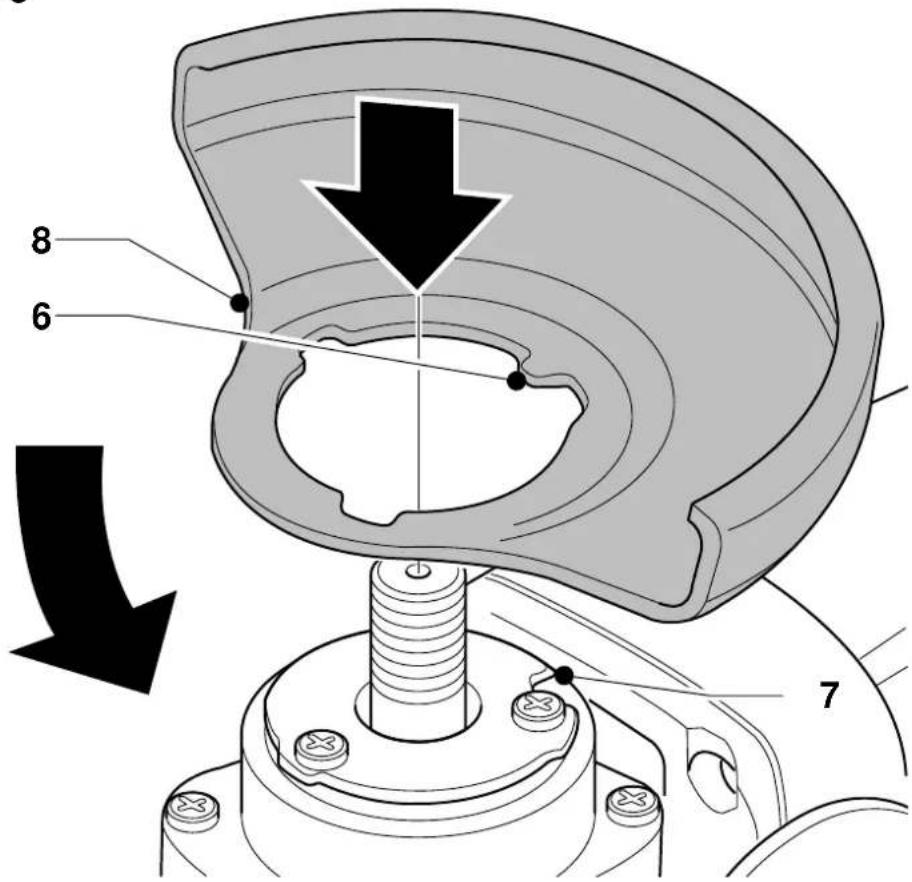
DW830 - Mounting (fig. B1 & C1)
- Place the angle grinder on a table, spindle up.
- Align the lug (6) with the slot (7) in the bracket.
- Press the guard (8) down and turn it in the direction of the arrow (fig. B1).

The guard locking pin (9) prevents the guard from coming loose.
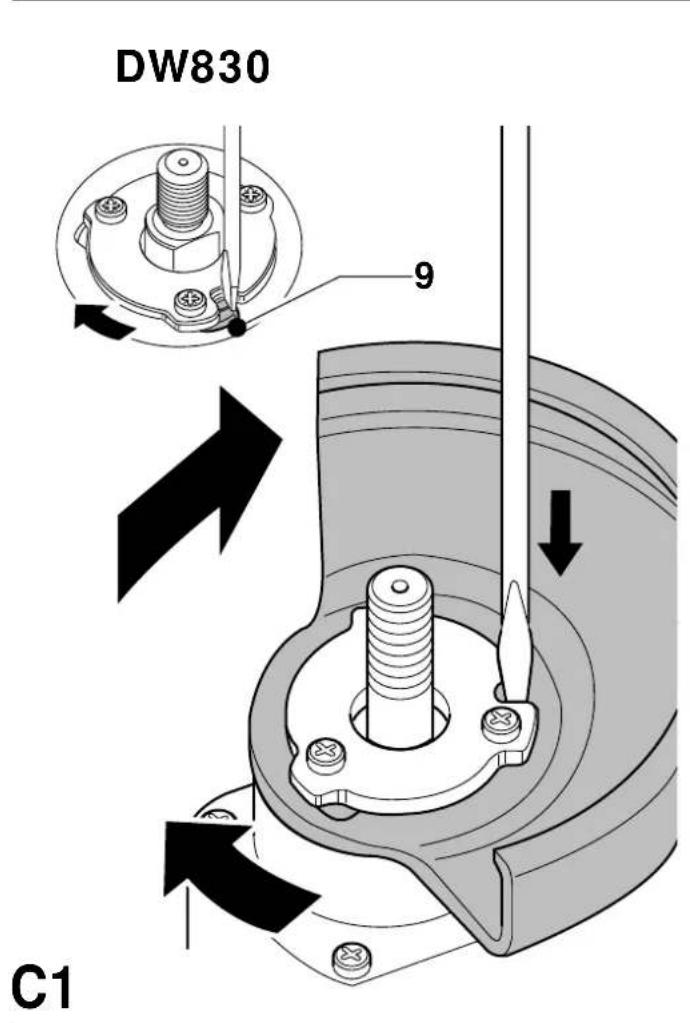
DW830 - Removing (fig. B1 & C1)
- Hold the tool in your hand.
- Rotate the guard (8) in the direction of the arrow (fig. C1).
- Use a screwdriver to press the locking pin (9) in the slot.
- Release the guard.
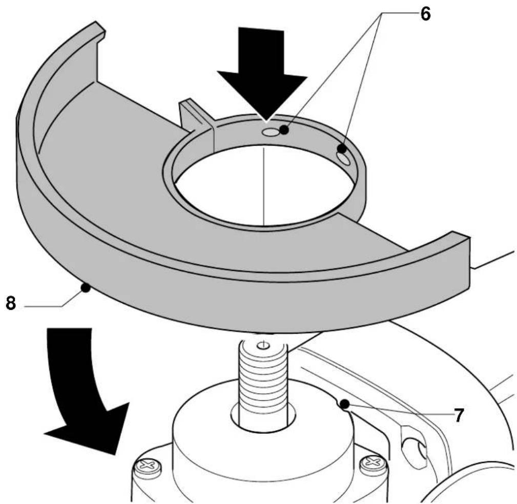
DW840/DW841 - Mounting (fig. B2 & C2)
- Place the angle grinder on a table, spindle up.
- Align the lugs (6) with the slots (7).
- Press the guard (8) down and turn it in the direction of the arrow (fig. B2).
- Securely tighten the screws (9).
DW840/DW841 - Removing
- To remove the guard, proceed in reverse order.
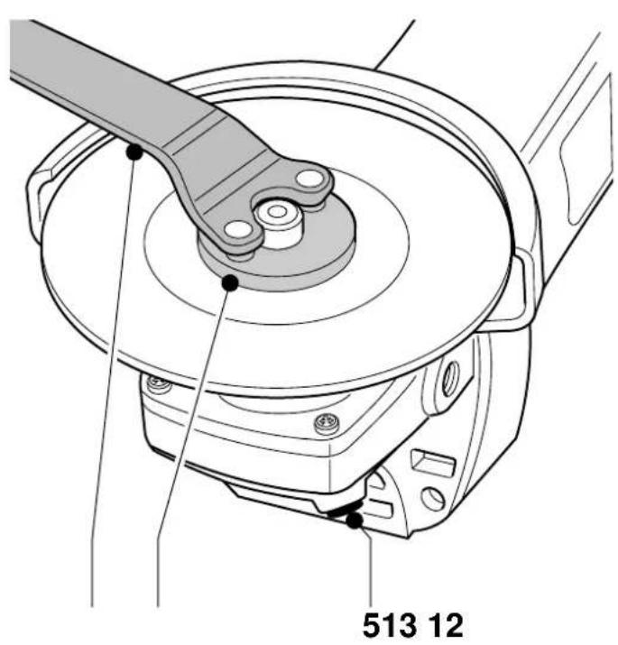
Mounting and removing a grinding wheel or cutting disk (fig. D & E)
- Place the tool on a table, guard up.
- Fit the spacer (11) correctly onto the spindle (10).
- Place the grinding wheel or cutting disk on the spacer.
- Screw the threaded flange (12) onto the spindle (10).
- Press the spindle lock (5) and rotate the grinding wheel or cutting disk until it locks in position.
- Tighten the threaded flange using the two-pin spanner (13) supplied.
- Release the spindle lock.
- To remove the grinding wheel or cutting disk, loosen the threaded flange using the two-pin spanner (while the spindle lock is engaged).
Fitting a wire cup brush
- Screw the wire cup brush directly onto the spindle without using the spacer and threaded flange.
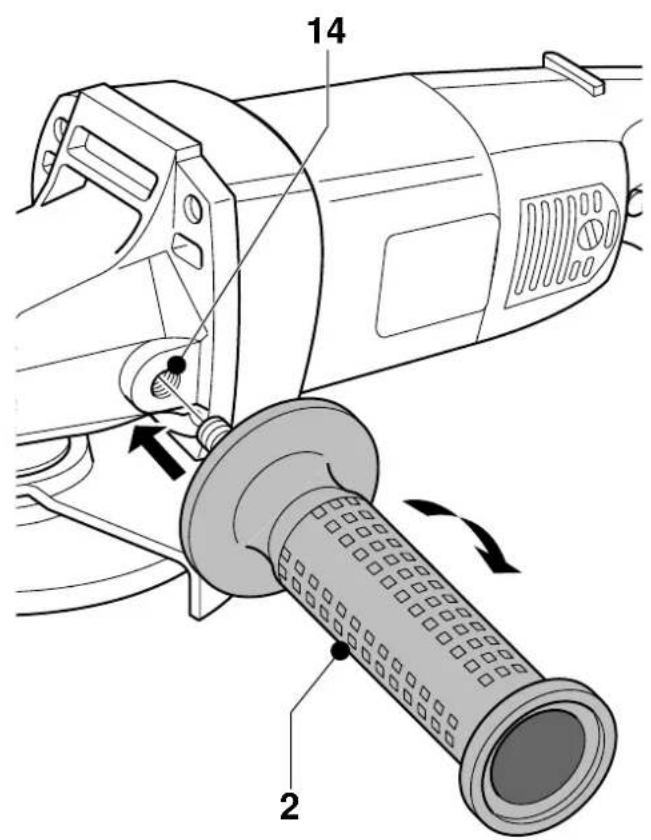
Mounting the side handle (fig. F)
- Screw the side handle (4) tightly into one of the holes (14) on either side of the gear case.
Instructions for use

• Always observe the safety instructions and applicable regulations.
- Ensure all materials to be ground or cut are secured in place.
- Apply only a gentle pressure to the tool. Do not exert side pressure on the grinding wheel or cutting disk.
- Avoid overloading. Should the tool become hot, let it run a few minutes under no load condition.
Prior to operation:
- Install the appropriate guard and disk or wheel. Do not use excessively worn disks or wheels.
- Be sure the spacer and threaded flange are mounted correctly.
- Make sure the disk or wheel rotates in the direction of the arrows on the accessory and the tool.
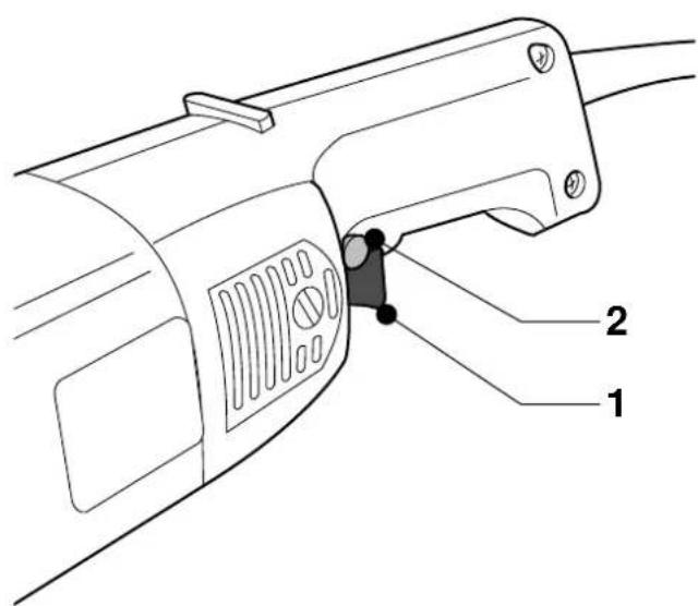
Switching ON and OFF (fig. G)
- To run the tool, press the lock-off button (2) and the ON/OFF-switch (1). For continuous operation, press the lock-on button (2) and release the ON/OFF-switch.
- To stop the tool, release the ON/OFF-switch. To stop the tool in continuous operation, press the ON/OFF-switch once more.

Do not switch the tool ON or OFF when under load.
Consult your dealer for further information on the appropriate accessories.
Maintenance
Your DeWALT Power Tool has been designed to operate over a long period of time with a minimum of maintenance. Continuous satisfactory operation depends upon proper tool care and regular cleaning.

Lubrication
Your Power Tool requires no additional lubrication.

Cleaning
Keep the ventilation slots clear and regularly clean the housing with a soft cloth.

Unwanted tools and the environment
Take your tool to an authorized DeWALT repair agent where it will be disposed of in an environmentally safe way.
GUARANTEE
- 30 DAY NO RISK SATISFACTION GUARANTEE If you are not completely satisfied with the performance of your DEWALT tool, simply return it within 30 days, complete as purchased, to the point of purchase, for a full refund or exchange. Proof of purchase must be produced.
• ONE YEAR FREE SERVICE CONTRACT •
If you need maintenance or service for your DEWALT tool, in the 12 months following purchase, it will be undertaken free of charge at an authorized DEWALT repair agent. Proof of purchase must be produced. Includes labour and spare parts for Power Tools. Excludes accessories.
• ONE YEAR FULL WARRANTY •
If your DEWALT product becomes defective due to faulty materials or workmanship within 12 months from the date of purchase, we guarantee to replace all defective parts free of charge or, at our discretion, replace the unit free of charge provided that:
• The product has not been misused.
• Repairs have not been attempted by unauthorized persons.
- Proof of purchase date is produced. This guarantee is offered as an extra benefit and is additional to consumers statutory rights.
For the location of your nearest authorized DEWALT repair agent, please use the appropriate telephone number on the back of this manual.
AMOLADORA ANGULAR DW830/DW840/DW841
¡Enhorabuena!
Director Engineering & Product Development Horst Großmann
text_image
X. fopmanMEULEUSE D'ANGLE DW830/DW840/DW841
Félicitations!
L'emballage contient:
Director Engineering & Product Development Horst Großmann
text_image
X. JopmannDEWALT, Richard-Klinger-Straße 40, D-65510, Idstein, Duitsland
Director Engineering & Product Development Horst Großmann

text_image
X. fopmanDEWALT, Richard-Klinger-Straße 40, D-65510, Idstein, Tyskland
Sikkerhetsforskrifter
REBARBADORA DW830/DW840/DW841
Parabéns!
Director Engineering & Product Development Horst Großmann
X. fopmann
DEWALT, Richard-Klinger-Straße 40, D-65510, Idstein, Alemanha
15 Tire as chaves de aperto
Director Engineering & Product Development Horst Großmann
text_image
X. JopmanDW840/DW841 - Irrotus
VINKELSLIPAR DW830/DW840/DW841
Vi gratulerar!
Director Engineering & Product Development Horst Großmann
X. fopmann
DEWALT, Richard-Klinger-Straße 40, D-65510, Idstein, Tyskland
Säkerhetsinstruktioner
DW840/DW841 - Demontering
TAŞLAMA MAKİNESİ DW830/DW840/DW841
Tebrikler!
Calpe House Rock Hill
Black Rock, Co. Dublin
Fax: 00353-2781811
Italia
DEWALT Tel: 0800-014353
Viale Elvezia 2
20052 Monza (Mi)
Fax: 039-2387592
Nederland
DEWALT Tel: 076 50 02 000
Florijnstraat 10
4879 AH Etten-Leur
Fax: 076 50 38 184
www.dewalt.benelux.com
Norge
DEWALT Tel: 22 99 99 00
Strømsveien 344
1011 Oslo
Fax: 22 99 99 01
www.dewalt-nordic.com
Österreich
DEWALT Tel: 01 - 66116 - 0