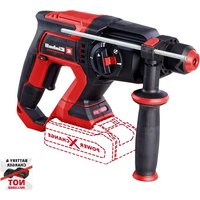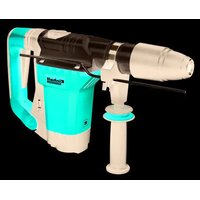
TP-RH 40 E - Hammer EINHELL - Free user manual and instructions
Find the device manual for free TP-RH 40 E EINHELL in PDF.


User questions about TP-RH 40 E EINHELL
0 question about this device. Answer the ones you know or ask your own.
Ask a new question about this device
Download the instructions for your Hammer in PDF format for free! Find your manual TP-RH 40 E - EINHELL and take your electronic device back in hand. On this page are published all the documents necessary for the use of your device. TP-RH 40 E by EINHELL.
USER MANUAL TP-RH 40 E EINHELL
natural_image
Close-up of a mechanical drill bit with labeled component 6 (no text or symbols beyond label)
text_image
3 7 11 6-2-


text_image
4 1.2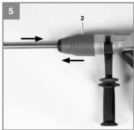
natural_image
Close-up of a drill bit with labeled parts (no text or symbols beyond labels)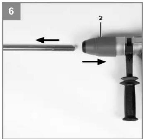
natural_image
Close-up of a mechanical tool with a drill bit and labeled component (no text or symbols beyond labels)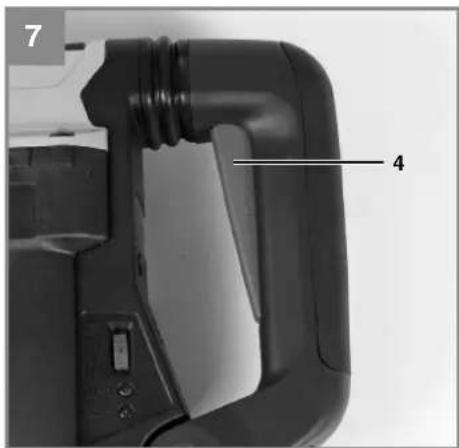
text_image
7 4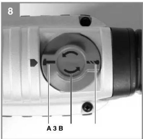
text_image
8 A 3 B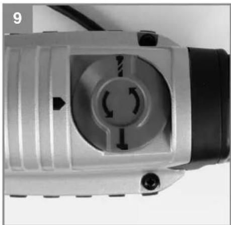
natural_image
Close-up of a mechanical device with a central circular component and directional arrows, no visible text or symbols.

text_image
10 8 9 10D
Inhaltsverzeichnis
- Safety regulations
- Layout and items supplied
- Proper use
- Technical data
- Before starting the equipment
- Operation
- Replacing the power cable
- Cleaning, maintenance and ordering of spare parts
- Disposal and recycling
- Storage
GB

Caution - Read the operating instructions to reduce the risk of inquiry

Wear ear-muffs. The impact of noise can cause damage to hearing.

Wear a breathing mask. Dust which is injurious to health can be generated when working on wood and other materials. Never use the device to work on any materials containing asbestos!

Wear safety goggles. Sparks generated during working or splinters, chips and dust emitted by the device can cause loss of sight.

Select between the individual functions only when the equipment is at a standstill. If you fail to observe this point, the equipment may be damaged.
GB
⚠️ Important!
When using the equipment, a few safety precautions must be observed to avoid injuries and damage. Please read the complete operating instructions and safety regulations with due care. Keep this manual in a safe place, so that the information is available at all times. If you give the equipment to any other person, hand over these operating instructions and safety regulations as well. We cannot accept any liability for damage or accidents which arise due to a failure to follow these instructions and the safety instructions.
1. Safety regulations
The corresponding safety information can be found in the enclosed booklet.
Caution!
Read all safety regulations and instructions.
Any errors made in following the safety regulations and instructions may result in an electric shock, fire and/or serious injury.
Keep all safety regulations and instructions in a safe place for future use.
2. Layout and items supplied
2.1 Layout (Fig. 1)
- Dust protection
- Locking sleeve
- Operating mode selector switch
- On/Off switch
- Anti-vibration handle
- Additional anti-vibration handle
- Depth stop
- Power controller
- Brush wear / overload indicator
- Power indicator
- Clamping screw
2.2 Items supplied
- Open the packaging and take out the equipment with care.
- Remove the packaging material and any packaging and/or transportation braces (if available).
• Check to see if all items are supplied. - Inspect the equipment and accessories for transport damage.
- If possible, please keep the packaging until the end of the guarantee period.
Important!
The equipment and packaging material are not toys. Do not let children play with plastic bags, foils or small parts. There is a danger of swallowing or suffocating!
- Depth Stop
• Original operating instructions - Safetyinstructions
3. Proper use
The tool is designed for drilling with hammer action in concrete, rock and brick, as well as for chiseling work, always using the respective correct drill or chisel bit.
The equipment is to be used only for its prescribed purpose. Any other use is deemed to be a case of misuse. The user / operator and not the manufacturer will be liable for any damage or injuries of any kind caused as a result of this.
4. Technical data
Mains voltage: 230 V \~ 50 Hz
Power input: 1010 W
Idling speed: 200-350 rpm
Blow rate: 1900-3300 rpm
Drilling capacity in concrete/stone (max.): 40 mm
Protection class: .....II /回
Weight: 6.0 kg
Impact energy: 8.7 J
Max. impact energy (short-time): 11 J
The impact energy values were measured with the new EPTA 05 method and therefore may be approx. 30% lower than the values taken with previous methods.
Sound and vibration
Sound and vibration values were measured in accordance with EN 60745.
L_pA sound pressure level ..... 95 dB(A)
K_pA uncertainty 3 dB
L_WA sound power level 106 dB(A)
K_WA uncertainty 3 dB
GB
The hammer drill is not designed for outdoors use as specified | Article 3 of Directive 2000/14/EC_2005/88/EC.
Wear ear-muff s.
The impact of noise can cause damage to hearing.
Total vibration values (vector sum of three directions) determined in accordance with EN 60745.
Hammer drilling in concrete
Vibration emission value a_h = 13.5 m/s^2 K uncertainty = 1.5 m/s ^2
Chiseling
Vibration emission value a_h = 11.5 m/s^2 K uncertainty = 1.5 m/s ^2
Warning!
The specified vibration value was established in accordance with a standardized testing method. It may change according to how the electric equipment is used and may exceed the specified value in exceptional circumstances.
The specified vibration value can be used to compare the equipment with other electric power tools.
The specified vibration value can be used for initial assessment of a harmful effect.
Keep the noise emissions and vibrations to a minimum.
- Only use appliances which are in perfect working order.
• Service and clean the appliance regularly.
• Adapt your working style to suit the appliance.
• Do not overload the appliance. - Have the appliance serviced whenever necessary.
- Switch the appliance off when it is not in use.
• Wear protective gloves.
Residual risks
Even if you use this electric power tool in accordance with instructions, certain residual risks cannot be rules out. The following hazards may arise in connection with the equipment's construction and layout:
- Lung damage if no suitable protective dust mask is used.
- Damage to hearing if no suitable ear protection is used.
- Health damage caused by hand-arm vibrations if the equipment is used over a prolonged period or is not properly guided and maintained.
5. Before starting the equipment
Hold the equipment by the insulated handles when carrying out work during which the plug-in tool could strike concealed power cables or its own mains lead. Contact with a live cable can also make the metal parts of the equipment live and will cause an electric shock.
Before you connect the equipment to the mains supply make sure that the data on the rating plate are identical to the mains data.
Always pull the power plug before making adjustments to the equipment.
Check the drilling point for concealed electrical cables, gas and water pipes using a cable/pipe detector.
5.1 Additional handle (Fig. 2 - Item 6)
For safety reasons you must only use the hammer drill with the additional handle.
The additional handle (6) enables you to achieve better stability whilst using the equipment. Do not use the equipment without the additional handle.
- To adjust the additional handle, slacken it by turning counter-clockwise.
- Now swivel the additional handle into the required position and then re-tighten it.
- The additional handle on these models is fastened to the machine housing by means of vibration-absorbing elements which protect the user and reduce fatigue during operation.
- The additional handle (6) is suitable for both left-handed and right-handed users.
GB
5.2 Depth stop (Fig. 3 - Item 7)
The depth stop (7) is held in place with the locking screw (11) on the additional handle (6) by means of a clamp.
- Undo the locking screw (11) and fit the depth stop (7).
- Set the depth stop (7) to the same level as the drill bit.
- Pull the depth stop (7) back by the required drilling depth.
• Retighten the locking screw (11). - Now drill the hole until the depth stop (7) touches the workpiece.
5.3 Inserting the tool (Fig. 4/5)
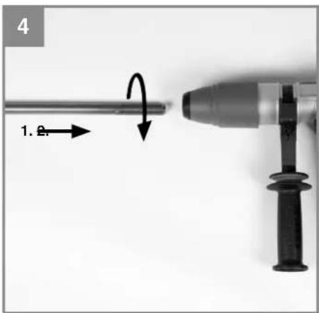
Clean the tool before fi tting it and apply a thin coating of bit grease to the tool shaft. Insert the tool into the tool mounting and turn it until the grooves coincide as shown in Fig. 4. Now hold the locking sleeve (2) in the front position and push the tool to the rear until it latches home as shown in Fig. 5. When this happens you will hear a clear click.
Check that the bit is locked in placed by pulling on it.
5.4. Tool removal (Fig. 6)
Pull back and hold the locking sleeve (2) and remove the tool.
6. Operation
Important.
To prevent all danger, the machine must only be held using the two handles (5 / 6). Otherwise there may be a risk of suffering an electric shock if you drill into cables.
6.1 ON/OFF switch (Fig. 7/Item 4)
- First fit a suitable drill bit into the tool (see 5.3).
- Connect the mains plug to a suitable socket.
- Position the drill in the position you wish to drill.
To switch on:
Press the ON/OFF switch (4)
To switch off :
Release the ON/OFF switch (4).
Warning: At low temperatures below 0^ C or when the equipment has not been used for a long time, there may be only little hammering effect or no hammering effect at all because the grease has not reached the necessary temperature. In this case let the equipment run in idle for approx. 90 seconds so that it can warm up. This will improve the equipment's lubrication and extend its working life.
6.2 Switching between hammer drilling and chiseling (Fig. 8)
Important! Turn the operating mode selector switch only in the indicated direction (counterclockwise). Select between the individual functions only when the equipment is at a standstill. If you fail to observe this point, the equipment may be damaged.
Hammer drilling
Turn the operating mode selector switch (3) clockwise until the mark on the equipment points to position B (drill bit).
Important!
You only require slight contact pressure for hammer drilling. Excessive contact pressure will place unnecessary strain on the motor. Check drill bits at regular intervals. Sharpen or replace blunt drill bits.
Chiseling
Turn the operating mode selector switch (3) clockwise until the mark on the equipment points to position A (hammer).
6.3 Changing the chisel position (Fig. 9)
- Insert the tool into the mount as described in section 5.3 „Inserting the tool“.
- Turn the operating mode selector switch (3) into the position „Change chisel position“ as shown in Fig. 9.
- Turn the tool by hand into the required position.
- Return the operating mode selector switch (3) into the position „Hammer“, then turn the tool by hand slightly to the left and right until it latches home.
Warning: During chiseling work, the operating mode selector switch (3) must always be in the position „Hammer“.
GB
6.4 Power adjustment (Fig. 10)
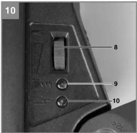
A suitable speed, blow rate and impact energy are selected by turning the power controller (8). The constant electronics keeps the speed, blow rate and impact energy constant regardless of the load, thus ensuring smooth performance. The following values are recommended.
Adjusting wheel A-B
Plaster / lightweight materials
Adjusting wheel C-D
Bricks / removing tiles
Adjusting wheel E-F
Drilling in concrete
Adjusting wheel G
Chiseling in concrete
The speed, blow rate and impact energy are increased by turning the power controller (8) from A to F. While this is happening, the power indicator (10) will blink green. The highest power is set by turning the power controller (8) into position G. This setting is characterized by a higher impact energy of up to 11 J. The power indicator (10) is then lit green continuously.
Warning: Use of the highest power setting G is recommended only for chiseling and for short periods in hammer drilling mode. Working for long periods in the highest setting will cause the user to tire quickly and will subject the electric tool to greater wear.
6.5 Brush wear / overload indicator
- The brush wear / overload indicator (10) will light up red if the equipment is overloaded. Check the equipment settings. During chiseling work, the operating mode selector switch (3) must be in the position „Hammer“ (Fig. 8 / Item A).
- If the brush wear / overload indicator (10) begins to flicker and the electric tool continues to work normally, you must change the brushes. The brushes will be totally worn after approx. 8 hours more work. The electric tool will then turn off automatically and the indicator will continue to flicker with a red light. For information about changing the brushes, refer to section 8.2 „Carbon brushes“.
- If the electric tool fails to work before the 8-hour warning period is over and the red brush wear / overload indicator (10) flickers,
this means that the electric motor is probably damaged.
7. Replacing the power cable
If the power cable for this equipment is damaged, it must be replaced by the manufacturer or its after-sales service or similarly trained personnel to avoid danger.
8. Cleaning, maintenance and ordering of spare parts
Always pull out the mains power plug before starting any cleaning work.
8.1 Cleaning
- Keep all safety devices, air vents and the motor housing free of dirt and dust as far as possible. Wipe the equipment with a clean cloth or blow it with compressed air at low pressure.
• We recommend that you clean the device immediately each time you have finished using it. - Clean the equipment regularly with a moist cloth and some soft soap. Do not use cleaning agents or solvents; these could attack the plastic parts of the equipment. Ensure that no water can seep into the device. The ingress of water into an electric tool increases the risk of an electric shock.
8.2 Carbon brushes
In case of excessive sparking, have the carbon brushes checked only by a qualified electrician. Important! The carbon brushes should not be replaced by anyone but a qualified electrician.
8.3 Maintenance
There are no parts inside the equipment which require additional maintenance.
GB
8.4 Ordering replacement parts:
Please quote the following data when ordering replacement parts:
• Type of machine
• Article number of the machine
• Identification number of the machine
- Replacement part number of the part required For our latest prices and information please go to www.isc-gmbh.info
9. Disposal and recycling
The equipment is supplied in packaging to prevent it from being damaged in transit. The raw materials in this packaging can be reused or recycled. The equipment and its accessories are made of various types of material, such as metal and plastic. Never place defective equipment in your household refuse. The equipment should be taken to a suitable collection center for proper disposal. If you do not know the whereabouts of such a collection point, you should ask in your local council offices.
10. Storage
Store the equipment and accessories out of children's reach in a dark and dry place at above freezing temperature. The ideal storage temperature is between 5 and 30^ . Store the electric tool in its original packaging.
GB

For EU countries only
Never place any electric power tools in your household refuse.
To comply with European Directive 2002/96/EC concerning old electric and electronic equipment and its implementation in national laws, old electric power tools have to be separated from other waste and disposed of in an environment-friendly fashion, e.g. by taking to a recycling depot.
Recycling alternative to the return request:
As an alternative to returning the equipment to the manufacturer, the owner of the electrical equipment must make sure that the equipment is properly disposed of if he no longer wants to keep the equipment. The old equipment can be returned to a suitable collection point that will dispose of the equipment in accordance with the national recycling and waste disposal regulations. This does not apply to any accessories or aids without electrical components supplied with the old equipment.
The reprinting or reproduction by any other means, in whole or in part, of documentation and papers accompanying products is permitted only with the express consent of the iSC GmbH.
Subject to technical changes
GB
Warranty certifi cate
Dear Customer,
All of our products undergo strict quality checks to ensure that they reach you in perfect condition. In the unlikely event that your device develops a fault, please contact our service department at the address shown on this guarantee card. Of course, if you would prefer to call us then we are also happy to offer our assistance under the service number printed below. Please note the following terms under which guarantee claims can be made:
- These guarantee terms cover additional guarantee rights and do not affect your statutory warranty rights. We do not charge you for this guarantee.
- Our guarantee only covers problems caused by material or manufacturing defects, and it is restricted to the rectification of these defects or replacement of the device.
The following are also excluded from our guarantee: compensation for transport damage, damage caused by failure to comply with the installation/assembly instructions or damage caused by unprofessional installation, failure to comply with the operating instructions (e.g. connection to the wrong mains voltage or current type), misuse or inappropriate use (such as overloading of the device or use of non-approved tools or accessories), failure to comply with the maintenance and safety regulations, ingress of foreign bodies into the device (e.g. sand, stones or dust), effects of force or external influences (e.g. damage caused by the device being dropped) and normal wear resulting from proper operation of the device. This applies in particular to rechargeable batteries for which we nevertheless issue a guarantee period of 12 months. The guarantee is rendered null and void if any attempt is made to tamper with the device. - The guarantee is valid for a period of 2 years starting from the purchase date of the device. Guarantee claims should be submitted before the end of the guarantee period within two weeks of the defect being noticed. No guarantee claims will be accepted after the end of the guarantee period. The original guarantee period remains applicable to the device even if repairs are carried out or parts are replaced. In such cases, the work performed or parts fitted will not result in an extension of the guarantee period, and no new guarantee will become active for the work performed or parts fitted. This also applies when an on-site service is used.
- In order to assert your guarantee claim, please send your defective device postage-free to the address shown below. Please enclose either the original or a copy of your sales receipt or another dated proof of purchase. Please keep your sales receipt in a safe place, as it is your proof of purchase. It would help us if you could describe the nature of the problem in as much detail as possible. If the defect is covered by our guarantee then your device will either be repaired immediately and returned to you, or we will send you a new device.
Of course, we are also happy offer a chargeable repair service for any defects which are not covered by the scope of this guarantee or for units which are no longer covered. To take advantage of this service, please send the device to our service address.
F
Sommaire
X 2006/42/EC
Annex IV
Notified Body:
Notified Body No.:
Reg. No.
□2000/14/EC_2005/88/EC
□ Annex V
Annex VI
Noise: measured L_ = dB(A) ; guaranteed L_ = dB(A)
P = KW: L/∅ = cm ^mm
Notified Body:
□ 2004/26/EC
Emission No.:
Standard references: EN 60745-1; EN 60745-2-6;
EN 55014-1; EN 55014-2; EN 61000-3-2; EN 61000-3-3
Subject to change without notice
Archive-File/Record: NAPR005340
Documents registrar: Georg Riedel
Wiesenweg 22, D-94405 Landau/Isar



natural_image
Two horizontal grayscale color swatches with no text or symbols, showing contrast between dark and light shades (no text or symbols)




EH 06/2013 (01)