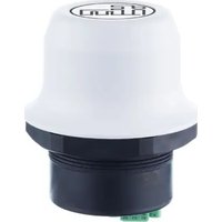
AE9000 - Router IFM - Free user manual and instructions
Find the device manual for free AE9000 IFM in PDF.


User questions about AE9000 IFM
0 question about this device. Answer the ones you know or ask your own.
Ask a new question about this device
Download the instructions for your Router in PDF format for free! Find your manual AE9000 - IFM and take your electronic device back in hand. On this page are published all the documents necessary for the use of your device. AE9000 by IFM.
USER MANUAL AE9000 IFM
Operating instructions
Industrial 4G LTE router EMEA
AE9000
Contents
1 Preliminary note 4
1.1 Legal and copyright information 4
1.2 Symbols used 4
1.3 Warnings.... 4
1.5 Change history 5
2 Safety instructions.... 6
2.1 General safety instructions 6
2.2 Network environment 6
2.3 SIM card 6
2.4 Network operator certified firmware.... 7
2.5 Distance between devices.... 7
2.6 Firewall and routing.... 7
3 Intended use.... 8
4 Installation.... 9
4.1 Installing the SIM card.... 9
4.2 Installing the device.... 9
5 Electrical connection.... 11
5.1 Connecting the device to Power over Ethernet (PoE) 11
5.2 Connecting the device to power and Ethernet.... 11
6 Operating and display elements 13
6.1 LEDs.... 13
6.1.1 Ethernet 13
6.2 Reset button 13
7 Configuration.... 14
7.1 Getting started 14
7.2 Accessing the web interface of the device.... 14
7.2.1 Configuring IP settings 14
7.2.2 Web interface login 15
7.3 Web interface: Overview 16
7.4 Factory settings.... 16
7.5 Ethernet settings.... 17
7.6 Cellular settings 17
7.6.1 Network settings 17
7.6.2 APN settings 18
7.6.3 Setting the SIM PIN and PUK 20
7.6.4 Enabling the SMS API.... 21
7.6.5 Enabling SMS communication 21
7.6.6 Sending SMS messages to the device 22
7.6.7 Notification SMS 23
7.7 NAT and port forward settings.... 23
7.8 VPN settings 24
7.9 Positioning settings 25
7.10 Configuration with REST API commands 26
7.11 Locking a configuration 27
7.12 Unlocking a configuration 28
7.13 Saving and rebooting 28
7.14 Application examples 28
7.14.1 Setting up the device with automatic APN assignment 28
7.14.2 Setting up the device as an internet router 29
7.14.3 Setting up the device with the ULPM REST API command 30
8 Operation 31
8.1 Viewing the system settings and network connection 31
8.2 Status LEDs 31
9 Troubleshooting 32
9.1 System log files.... 32
9.2 Diagnostic information.... 33
9.2.1 Mobile network 33
9.2.2 Historic diagnostics.... 34
9.2.3 Network diagnostics 34
9.3 Data connection termination 36
9.4 Rebooting the device 36
10 Maintenance, repair and disposal 37
10.1 Firmware update.... 37
10.2 Setting an administrator password 37
10.3 Settings backup 38
10.3.1 Creating a backup file 38
10.3.2 Restoring settings from the backup file 38
10.4 Reset and recovery 39
10.4.1 Factory reset using the reset button 39
10.4.2 Factory reset using the web interface 39
11 Appendix....41
11.1 SMS commands and returns.... 41
11.1.1 Help 42
11.1.2 ID 43
11.1.3 Info 44
11.1.4 IP 45
11.1.5 Mac.... 46
11.1.6 Mast 47
11.1.7 Phys 48
11.1.8 Ping destination 49
11.1.9 Pos 50
11.1.10 Reboot 51
11.1.11 Version 52
1 Preliminary note
You will find instructions, technical data, approvals, accessories and further information using the QR code on the device / packaging or at documentation.ifm.com.
1.1 Legal and copyright information
© All rights reserved by ifm electronic gmbh. No part of these instructions may be reproduced and used without the consent of ifm electronic gmbh.
All product names, pictures, companies or other brands used are the property of the respective rights owners.
- Manufacturer:
HMS Industrial Networks AB
Stationsgatan 37
302 50 Halmstad
Schweden
• Sales:
ifm electronic gmbh
Friedrichstraße 1
45128 Essen
Deutschland
1.2 Symbols used
√ Requirement
Instructions
Reaction, result
[...] Designation of keys, buttons or indications
→ Cross-reference

Important note
Non-compliance may result in malfunction or interference.

Information
Supplementary note
1.3 Warnings
Warnings indicate the possibility of personal injury and damage to property. This enables safe product handling. Warnings are graded as follows:

WARNING
Warning of serious personal injury
▷ If the warning is not observed, fatal and serious injuries are possible.

CAUTION
Warning of minor to moderate personal injury
▷ If the warning is not observed, minor to moderate injuries are possible.
ATTENTION
Warning of damage to property
▷ If the warning is not observed, damage to property is possible.
1.4 Exclusion of liability
The information contained in this document is for information purposes only. Please inform ifm electronic of any inaccuracies or omissions found in this document. ifm electronic disclaims any responsibility or liability for any errors that may appear in this document.
ifm electronic reserves the right to modify its products in line with its policy of continuous product development. The information in this document shall therefore not be construed as a commitment on the part of ifm electronic and is subject to change without notice. ifm electronic makes no commitment to update or keep current the information contained in this document.
The data, examples and illustrations found in this document are included for illustrative purposes and are only intended to help improve understanding of the functionality and handling of the product. In view of the wide range of possible applications of the product, and because of the many variables and requirements associated with any particular implementation, ifm electronic cannot assume responsibility or liability for actual use based on the data, examples or illustrations included in this document nor for any damages incurred during installation of the product. Those responsible for the use of the product must acquire sufficient knowledge in order to ensure that the product is used correctly in their specific application and that the application meets all performance and safety requirements including any applicable laws, regulations, codes and standards. Furthermore, ifm electronic will under no circumstances assume liability or responsibility for any problems that may arise as a result from the use of undocumented features or functional side effects found outside the documented scope of the product. The effects caused by any direct or indirect use of such aspects of the product are undefined and may include e.g. compatibility issues and stability issues.
1.5 Change history
| Issue | Subject | Date |
| 00 | New creation of the document | 04 / 2024 |
| 01 | Changed: supported PoE standard, Connecting the device to Power over Ethernet (PoE) (→ ☐ 11) | 11 / 2024 |
2 Safety instructions
- The unit described is a subcomponent for integration into a system.
- The system architect is responsible for the safety of the system.
-
The system architect undertakes to perform a risk assessment and to create documentation in accordance with legal and normative requirements to be provided to the operator and user of the system. This documentation must contain all necessary information and safety instructions for the operator, the user and, if applicable, for any service personnel authorised by the architect of the system.
-
Read this document before setting up the product and keep it during the entire service life.
- The product must be suitable for the corresponding applications and environmental conditions without any restrictions.
- Only use the product for its intended purpose (→ Intended use).
- If the operating instructions or the technical data are not adhered to, personal injury and/or damage to property may occur.
- The manufacturer assumes no liability or warranty for any consequences caused by tampering with the product or incorrect use by the operator.
- Installation, electrical connection, set-up, operation and maintenance of the product must be carried out by qualified personnel authorised by the machine operator.
- Protect units and cables against damage.
• Store the product in its original packaging.
2.1 General safety instructions
This device emits radio waves in the ISM (Industrial, Scientific, Medical) band.
▶ Make sure that all medical devices used in proximity to this device meet appropriate susceptibility specifications for this type of radio waves.
This device contains parts that can be damaged by electrostatic discharge (ESD).
▶ Observe ESD protective measures to prevent damage.
Minimum temperature rating of the cable to be connected to the field wiring terminals: 90 °C.
Only use copper wire for field wiring terminals.
This device is recommended for use in both industrial and domestic environments. For industrial environments it is mandatory to use the functional earth connection to comply with immunity requirements. For domestic environments the functional earth must be used if a shielded Ethernet cable is used in order to meet emission requirements.
2.2 Network environment
Ensure that you have all the necessary information about the capabilities and restrictions of your local network environment before installation.
2.3 SIM card
If a prepaid data plan is used, ensure that:
▶ the data amount is sufficient.
▶ any SMS notifications are sent to a monitored number.
2.4 Network operator certified firmware
To connect the device to a cellular (mobile-radio) network, you may need to install a firmware certified by the network operator on the device.
Before you start to configure the device:
▶ Ensure that the current firmware installed on the device is valid for the network operator you are going to use.
▶ You will find the firmware version number on the overview page of the device web interface.
For information on how to update the firmware refer to: Firmware update ( → ☐ 37)
2.5 Distance between devices
▶ For optimal reception, cellular devices should not be confined in buildings made of concrete or metal, without windows.
▶ To avoid interference, a minimum distance of 50 cm between cellular devices is to be observed.
▶ Always maintain a distance of at least 20 cm between the device and the user's body.
2.6 Firewall and routing
The device provides routing settings.
By default, the firewall allows routing of:
• outgoing traffic for TCP, UDP and ICMP (for lpv4 only)
• incoming traffic only for already established connections
Configuration options: NAT and port forward settings ( → ☐ 23)
3 Intended use
The device can be used as a communication interface and router.
The device receives and transmits data over Ethernet and cellular standard networks.

Notes relevant for approval: package insert of the device and documentation.ifm.com
4 Installation
4.1 Installing the SIM card
To connect the device to a cellular network, install a SIM card for communication with the desired cellular network.
Supported SIM card types:
• Nano SIM for IoT and M2M (for data communication)
• standard mobile phone Nano SIM
To install the SIM card:

▶ Disconnect the device from the supply voltage.
▶ Insert the SIM card into the SIM card holder of the device. Ensure that the SIM card contact surface is facing towards the Ethernet port.
▷ The SIM card is installed.
4.2 Installing the device
The device is intended to be mounted on top of a machine or cabinet. Mount it through an M50 hole (diameter: 50.5 mm) using the included sealing ring and nut.
Mounting surface
The mounting surface must be clean and free from oils and greases with a finish equivalent to Ra 3.2 or finer.
Installation position
For optimal reception, mobile devices require a zone around them clear of objects that could obstruct or reflect the signal.
▶ To avoid interference, a minimum distance of 50 cm between the device and other mobile devices should be observed.
▶ Make sure that the sealing ring is correctly placed in the circular groove in the top part of the housing before tightening the nut.
▶ Always hold the bottom part of the housing when untightening the nut, not the top part (the cap).

To install the device:
▶ Unscrew the nut from the bottom of the device.
▶ Insert the device through the hole from above.
▶ Place and tighten the nut on the bottom of the device. Tightening torque: 5 ± 0.5 Nm
▷ The device is installed.
5 Electrical connection
5.1 Connecting the device to Power over Ethernet (PoE)
Connecting the device to o Power Over Ethernet (PoE) and DC power simultaneously could damage both the power supply and the device.
▶ Make sure to use only one of the supply types at a time.
Both shielded and unshielded cables may be used for connection.
The device is designed to comply with the PoE standard to IEEE 802.3af (44-57 V DC).
Wiring:

1: Data: TD+ PoE: A+
2: Data: TD- PoE: A+
3: Data: RD+ PoE: A- (with pin 6)
4: n.c. PoE: B+
5: n.c. PoE: B+
6: Data: RD- PoE: A- (with pin 3)
7: n.c. PoE: B-
8: n.c. PoE: B-
Housing Shield Functional earth (FE)
To connect the device to PoE:

▶ Connect the device to a suitable network coupling element (e.g. PoE-capable Ethernet switch) via the Ethernet port (RJ45).
5.2 Connecting the device to power and Ethernet
ATTENTION
Connecting power with reverse polarity or using the wrong type of power supply
▷ Damage to the device
▶ Make sure that the power supply is connected correctly and of the recommended type.
Connecting the device to o Power Over Ethernet (PoE) and DC power simultaneously could damage both the power supply and the device.
▶ Make sure to use only one of the supply types at a time.

When the device is powered via a power supply unit, Functional Earth (FE) must be connected.
Wiring:

1: + (11-33 V DC)
2: - (11-33 V DC)
3: Functional earth (FE)
When the device is mounted on a sheet metal plate, connect Functional Earth (FE) to the plate directly next to the device.

To connect the device:

▶ Connect the device power connector to a power supply (11-33 V DC).
▶ Connect the device power connector to the Functional Earth (FE) of the system.

▶ Connect the device to the Ethernet network.
6 Operating and display elements
6.1 LEDs

A: L/A
B: Status
6.1.1 Ethernet
| LED | Description | Colour | Behaviour | Description |
| L/A | Link and activity | - | Off | No Ethernet connection |
| Yellow | Flashing | 10 Mbit/s Ethernet activity | ||
| Yellow | On | 10 Mbit/s Ethernet link established | ||
| Green | Flashing | 100 Mbit/s Ethernet activity | ||
| Green | On | 100 Mbit/s Ethernet link established | ||
| Status | Status | - | Off | No power |
| Blue | On | Connected on LTE | ||
| Blue / violet | Flashing alternately | Trying to connect | ||
| Purple | On | Connected on UTMS | ||
| Red | On | Recoverable / unrecoverable fault | ||
| Red | Flashing | No configured cellular interface / no SIM card / no valid configuration | ||
| Yellow | On | Device is booting or in sleep mode |
6.2 Reset button
The reset button is located on the bottom of the device.

Notes on use:
▶ Press the button with the help of a pointed object (e.g. a ballpoint pen or a match).
7 Configuration
7.1 Getting started
By default, the APN assignment of the device is set to automatically search for the SIM card APN setting and assign it to the device.
In cases where no additional parameter configuration via the device web interface is required: LINK When configuring the device, it must be switched on and connected to a laptop / PC.

▶ Connect the Ethernet port of the device to your laptop / PC.
▶ Connect the power connector of the device to a power supply.
▷ The device starts.
7.2 Accessing the web interface of the device
7.2.1 Configuring IP settings
To be able to access the web interface of the device, you may need to adjust the IP settings of your laptop / PC.

The default IP address is 192.168.1.1, the subnet mask is 255.255.255.0.
Option 1: Enabling DHCP on laptop / PC

▶ On your laptop / PC: Navigate to the IP settings.
▶ Enable DHCP for Ethernet interface.
▷ The laptop / PC receives a valid IP address in the same network segment as the device.
▷ The user can access the device's web interface with a laptop / PC.
Option 2: Setting a static IP address on your laptop / PC

▶ On your laptop / PC: Navigate to the IP settings.
▶ Manually assign an IP address within the same network segment as the device to the Ethernet interface.
▷ The user can access the device's web interface with a laptop / PC.
7.2.2 Web interface login
The web interface of the device can be accessed from a web browser.

▶ Before installing the device on a network, change the default username and password.

The device comes with a default username and password. The username is admin, the password is printed on the housing of the device.

The default IP address is 192.168.1.1, the subnet mask is 255.255.255.0.
To log in to the web interface of the device:
▶ Start web browser.
▶ Enter the device's IP address in the address bar of the web browser.

▶ Press [Enter].
▷ The login screen of the device web interface appears.

▶ Enter the username and a valid password.
▶ Click on [Sign In].
▷ The user is logged in to the web interface of the device.
▷ The web browser displays the [System Overview] page.
7.3 Web interface: Overview
The web interface is used to configure the device settings as well as for diagnostics and maintenance. The [System Overview] page shows the current settings and the connection status of the device.
| LTE Router Setup | |
| System Overview B Ethernet | |
| Ethernet | |
| Internal DHCP Server Enabled | |
| DHCP Table | |
| IP Address | MAC Address |
| 192.168.1.146 | 88:a4:c2:e1:a0:27 |
| Cellular | |
| Data Connection No Signal Strength Strong signal (4) Operator o2 - de SIM Card SIM card inserted and unlocked Status Registered, home network Network Type LTE network APN | |
| System | |
| Firmware 1.02.03 Time 2024-05-26 18:01:39 Uptime 1 minute 6 seconds | |
A: [System Overview] The menu page shows the current settings and the connection status of the device.
B: Left sidebar menu
- [System Overview]
- [Ethernet Settings]
- [Cellular Settings]
• [NAT/Port Forward Settings]
• [VPN Settings]
• [Positioning Settings]
• [Firmware Update]
- [System Logs]
- [System]
• [Diagnostics]
C: [Save and Reboot] button and [Cancel All Changes] button
7.4 Factory settings
The device comes with the following factory default settings:
| Parameter | Value |
| [IP Assignment] | Static |
| [IP Address] | 192.168.1.1 |
| [Subnet Mask] | 255.255.255.0 |
| [Default Gateway] | 192.168.1.1 |
| [Internal DHCP Server] | Enabled |
| [Network Type] | Modem Preset ListConnects automatically to an available network according to the following priority order: LTE, UMTS and GSM mobile network |
| [Incoming Traffic] | NAT/Port Forward incoming traffic is enabled |
To restore the factory settings:
• Factory reset using the reset button ( → ☐ 39)
• Factory reset using the web interface ( → ☐ 39)
7.5 Ethernet settings
The user can adjust the IP settings of the Ethernet interface to integrate the device into the internal Ethernet network.
IP address
The default IP address is 192.168.1.1.
Subnet mask
The subnet mask identifies the subnetwork to which the static IP address belongs. The default subnet mask is 255.255.255.0.
Internal DHCP server
If the DHCP server is enabled, the IP address of the Ethernet interface is set automatically.

By default, the internal DHCP server is enabled.
▶ To avoid interference, keep only one DHCP server enabled on the network.
The DHCP server is only enabled for the LAN interface.
IP address range
You can set an address range for the IP address assignment by the internal DHCP server.
By default, the address range is 192.168.1.100 to 192.168.1.200.
To change the IP settings of the device:
▶ Go to the [Ethernet Settings] menu page.
▶ Navigate to the [IP Settings] area.
▶ Enter the IP address in the [IP Address] field.
▶ Enter the subnet mask in the [Subnet Mask] field.
▶ Optional: Configure the DHCP server settings.
▶ In the left sidebar menu: Click [Save and Reboot].
▷ The device reboots.
▷ The changes to the settings take effect.
7.6 Cellular settings
When you are going to connect the device to a cellular network, ensure that the SIM card is correctly inserted in the SIM card holder.
▶ Refer to: Installing the SIM card ( → ☐ 9)
7.6.1 Network settings
Select the mobile network type to which the device can connect via the parameter [Preferred Network Type].
The most recently registered network type takes precedence.
When a specific Preferred Network Type is selected and available, the device might remain locked to that network type, even if you select the option [Modem Preset List].
▶ If the device is locked to a network type you do not want to use, ensure that the network type is no longer available to the device.
▷ The device then selects the next available network type.
Available options:
| Option | Description |
| [Modem Preset List] | Use the Modem Preset List as search order for Radio Access Technology (RAT)Automatically connects to an available network according to the following priority order: LTE, UMTS and GSM mobile network. The device scans for all available Public Land Mobile Networks (PLMN) in each RAT. |
| [LTE] | Use LTE networks |
| [UMTS] | Use UMTS networks |

Requirements:
√ The SIM card is inserted correctly.
▶ Go to the [Cellular Settings] menu page.
▶ Navigate to the [Network Settings] area.
▶ Select a [Preferred Network Type] from the list.
▷ The network type is set.
7.6.2 APN settings
Automatic APN assignment
An APN (Access Point Name) automatically derived from the SIM card may not give full access to the cellular network.
▶ Follow your network operator's guidelines.
By default, the device is set to automatically search for the SIM card APN setting.
If a general APN string is available for the network operator, it will be set as the APN assignment.
▶ Ensure that the general APN string is recommended by the network operator and in accordance with the SIM card IoT data plan.

Requirements:
√ The SIM card is inserted correctly.
▶ Go to the [Cellular Settings] menu page.
▶ Navigate to the [APN Settings] area.
▶ Under [APN Assignment], select [Automatic].
▷ The APN is assigned automatically.
Manual APN assignment

Requirements:
√ The SIM card is inserted correctly.
√ Ensure that you have the APN access data supplied by your carrier available.
▶ Go to the [Cellular Settings] menu page.
▶ Navigate to the [APN Settings] area.
▶ Under [APN Assignment], select [Manual].
▷ Additional input fields appear.
▶ In the [APN] field, enter the APN string.
▷ The APN is set.
APN authentication
By default, APN authentication is disabled. When enabled, the PAP authentication method is used.
APN authentication is to be configured only if your carrier has set up the APN with a username and password.

To activate APN authentication:
Requirements:
√ The SIM card is inserted correctly.
▶ Go to the [Cellular Settings] menu page.
▶ Navigate to the [APN Settings] area.
▶ In the field [APN Authentication], select [Yes (PAP)].
▶ In the [User] field, enter the username.
▶ In the [Password] field, enter the correct password.
▶ In the left sidebar menu: Click [Save and Reboot].
▷ The device reboots.
▷ APN authentication is active.
7.6.3 Setting the SIM PIN and PUK
To manage the SIM card:
Requirements:
√ The SIM card is inserted correctly.
▶ Go to the [Cellular Settings] menu page.
▶ Navigate to the [SIM PIN and PUK] section.
SIM card PIN code
If the installed SIM card is locked with a PIN code, it must be entered.

▶ In the [Enter PIN] field, enter the valid PIN code.
▶ Click [Validate].
▷ The device attempts to activate the SIM card with the entered PIN.
▷ The [Status] field shows the current status.
SIM card PUK code
If you have entered the wrong PIN code three times in a row, the SIM card is blocked. To unlock the SIM card, enter a new PIN code and the valid PUK code.

▶ In the [Desired (new) PIN] field, enter the new PIN code.
▶ In the [PUK code] field, enter the valid PUK code.
▶ Click [Apply].
▷ The device checks the validity of the PUK code and sets the new PIN code.
▷ The [Status] field shows the current status.
Check the maximum number of attempts to enter the correct PUK code that applies to your operators' SIM cards. If you enter the wrong PUK code too many times, the SIM card becomes permanently locked.
SIM card without PIN code
If a SIM card without PIN verification is used, the following error message appears:
| SIM PIN and PUK | |
| Status | PIN not required for current SIM. None is configured or validated. |
7.6.4 Enabling the SMS API
The SMS application of the device can receive, parse and respond to SMS.
By default, [Handle incoming SMS] is set to [Externally via API].
SMS sending is done via the SMS REST API. The device does not parse or respond to the SMS.

To enable the SMS API:
Requirements:
√ The SIM card is inserted correctly.
▶ Go to the [Cellular Settings] menu page.
▶ Navigate to the [SMS Settings] area.
▶ In the [Handle incoming SMS] menu, select [Externally via API].
▶ Set up the device as an internet router, see Setting up the device as an internet router ( → ☐ 29).
▶ Send REST commands to the device, see Configuration with REST API commands (→ ☐ 26).
7.6.5 Enabling SMS communication
The SMS application of the device can receive, forward and respond to SMS with status information.
By default, [Handle incoming SMS] is set to [Externally via API].

Requirements:
√ The SIM card is inserted correctly.
▶ Go to the [Cellular Settings] menu page.
▶ Navigate to the [SMS Settings] area.
▶ In the [Handle incoming SMS] menu, select [Internally in Bolt LTE].
▶ In the [Access code] field, enter a unique access code.
To prevent unauthorised access to the device, each SMS must start with an access code. If no access code is defined, SMS parsing is disabled. The access code must consist of at least one character.
The access code set here must be included in each SMS sent to the device, see Sending SMS messages to the device ( → ☐ 22)
▶ In the [Trusted numbers] fields, enter up to 3 mobile phone numbers from which the device will accept SMS.
▶ In the [Site name] field, enter a label to identify the device. The site name is included in the automatically generated welcome SMS sent from the device.
▶ In the left sidebar menu: Click [Save and Reboot].
▷ The device reboots.
▷ The changes to the settings take effect.
▷ The device sends a welcome SMS to the trusted numbers.
Example: trusted numbers
• Trusted number: +4635172900
- Country code: +46
– National destination code: 035
– Subscriber number: 172900
7.6.6 Sending SMS messages to the device
Available SMS commands: SMS commands and returns ( → 41)
Requirements:
√ The phone number of the mobile device is set as a trusted number in the device, see Enabling SMS communication ( → ☐ 21).
√ The phone number for the SIM card installed in the device is available.
√ The access code for the device is configured and available, see Enabling SMS communication ( → ☐ 21).
▶ On the mobile device, start a new SMS.
▶ Enter the phone number of the device to which you are sending the SMS.
▶ Enter the access code and SMS command.
▶ Send the SMS.
▷ Depending on which SMS command is sent, the device returns an SMS containing information or a prompt with instructions on how to continue.
Example: Send the SMS command help to get a list with all available commands
▶ Enter the access code.

▶ Enter the SMS command.

▶ Send the SMS.
▷ The device returns a message containing the requested information.
my_access_code help
Syntax:
access_code cmd
cmd list:
help
id
info
ip
mac
mast
phys
ping destination
pos
reboot
version
7.6.7 Notification SMS
At certain times, the device will attempt to send notification SMS to the mobile devices with the trusted numbers.

If the device is unable to send the SMS notification message at boot, no further attempts to send the SMS will be made.
The device sends a notification SMS when:
• a new trusted phone number is added:
- SMS sent to newly added phone number
• a trusted phone number is removed:
- SMS sent to removed phone number
• the device is in SMS parsing state
- SMS sent to all trusted phone numbers on configuration change
7.7 NAT and port forward settings
The NAT and port forward function is used to allow incoming traffic from an external cellular mobile-radio network access to a device IP address on the internal Ethernet network.
The Source Filter setting is used to prevent unauthorised data traffic on the local network. The source filter defines which IP addresses from external networks have access to the local IP address.
Available options:
| Option | Description |
| [Network] | Allow any IP address on a specific network to access the local IP address.► ▶ Enter [Source base IP] and [Source IP netmask]. |
| [Range] | Allow a specific IP address range to access the local IP address.► ▶ Enter [Source IP range start] and [Source IP range stop]. |
| [Host(s)] | Allow (a) specific host(s) to access the local IP address.► ▶ Enter up to 5 [Source IP(s)]. |
| [Any] | Allow any external IP address to access the local IP address. |
By default, the NAT port forward function is disabled. All incoming traffic from the external network is rejected.

To enable the NAT/port forward function:
▶ Open the [NAT/Port-Forward Settings] menu.
▶ Navigate to the [NAT] section.
▶ In the [Incoming Traffic] drop-down menu, select [NAT 1:1].
▶ In the [Local IP to receive all traffic] field, enter the IP address to receive all incoming traffic.
▶ In the [Source Filter] drop-down menu, select the desired option.
▷ The NAT/port forward function is configured.
▷ The communication is redirected to one specific device IP address on the local network that will receive all incoming traffic from the external network.
7.8 VPN settings
The device offers an OpenVPN Client function. OpenVPN Client is used to secure and encrypt the data sent between the device and a VPN server over the cellular network.
By default, OpenVPN Client is disabled.
For configuration, the OpenVPN configuration file (.ovpn) of the OpenVPN server is required.
| VPN Settings | |
| VPN Settings | OpenVPN Traffic Stats |
| Tunnel Read 7812 bytes Tunnel Write 7476 bytes | |
| OpenVPN Log | |
| 2023-03-01 11:20:53 DEPRECATED OPTION: --cipher set to 'AES-256-CBC' but missing in --data-ciphers (AES-256-GCM:AE) 2023-03-01 11:20:53 OpenVPN 2.5.7 arm-poky-linux-gnueabi [SSL (OpenSSL)] [LZO] [LZ4] [EPOLL] [MH/PKTINFO] [AEAD] b 2023-03-01 11:20:53 library versions: OpenSSL 1.0.2p 14 Aug 2018, LZO 2.10 2023-03-01 11:20:53 Outgoing Control Channel Authentication: Using 256 bit message hash 'SHA256' for HMAC authenti 2023-03-01 11:20:53 Incoming Control Channel Authentication: Using 256 bit message hash 'SHA256' for HMAC authenti 2023-03-01 11:20:54 TCP/UDP: Preserving recently used remote address: [AF_INET]81.92.218.8:1194 2023-03-01 11:20:54 Socket Buffers: R=[266240->266240] S=[266240->266240] 2023-03-01 11:20:54 NOTE: setsockopt TCP_NODELAY=1 failed 2023-03-01 11:20:54 UDP link local: (not bound) 2023-03-01 11:20:54 UDP link remote: [AF_INET]81.92.218.8:1194 2023-03-01 11:20:54 TLS: Initial packet from [AF_INET]81.92.218.8:1194, sid=3bad530f ca59baec 2023-03-01 11:20:54 net_route_v4_best_gw query: dst 0.0.0.0 2023-03-01 11:20:54 net_route_v4_best_gw result: via 100.65.245.148 dev rmnet_data0 2023-03-01 11:20:54 VERIFY OK: depth=1, CN=CloudVPN Prod CA 2023-03-01 11:20:54 VERIFY KU OK | |
To connect the device to an OpenVPN server:
Requirements:
√ ▷ The OpenVPN configuration file is available.
▶ Open the [VPN Settings] menu page.
▶ Navigate to the [VPN Settings] area.
▶ In the [OpenVPN Client] drop-down menu, select [Enabled].
▶ Next to [OpenVPN Config File], click [Choose File].
▷ A dialogue window appears.
▶ Select the OpenVPN configuration file and click [Open] to load the file.
▶ Click [Send].
The OpenVPN configuration file is imported.
▶ In the left sidebar menu: Click [Save and Reboot].
▷ The device reboots.
▷ OpenVPN Client is enabled.
▷ The OpenVPN connection between the device and the OpenVPN server is established.
The menu page shows the following information:
• [OpenVPN Traffic Status]
The pane shows the status of the data traffic between the device and the OpenVPN server.
• [OpenVPN Log]
The pane shows log messages with entries for successful connections as well as failures and errors.
The messages start with the time stamp (date, time).
7.9 Positioning settings
Use the positioning function to locate the position of the device.
By default, the positioning function is disabled.
To activate the positioning function:
▶ Open the [Positioning Settings] menu page.
▶ Navigate to the [Positioning Settings] area.
▶ Select [Enabled] from the [Positioning Service] drop-down menu.
▶ In the left sidebar menu: Click [Save and Reboot].
▷ The device reboots.
▷ The changes to the settings take effect.
After activating the positioning function, the [Current Position] pane displays the following information:
| Positioning Settings | ||
| Positioning Service | Enabled | |
| Current Position | ||
| Positioning Settings | Positioning Service State | Active |
| Valid Position | Yes | |
| Latitude | 88.902756 | |
| Longitude | 12.520808 | |
| Accuracy | 10m | |
| Parameter | Description | |
| [Positioning Service State] | Status of the positioning service• [Disabled]: service is disabled• [Enabled]: service is enabled | |
| [Valid Position] | Validity of position data• [Yes]: The satellite coverage is sufficient to provide a position• [No]: The satellite coverage is insufficient to provide a position (e.g. after activating the positioning service when the device is searching for available satellites; if the device is installed in a location where the satellite coverage is poor) | |
| [Latitude] | Latitude of the device position | |
| [Longitude] | Longitude of the device position | |
| [Accuracy] | Accuracy in metres | |
7.10 Configuration with REST API commands
The device has a REST API that allows the user to retrieve the device configuration settings.

For detailed information about the REST API and the available REST commands see: Operating instructions (supplement) - REST API - Commands
To send a REST command to the device:
Requirements:
√ The device is set up as an internet router, see Setting up the device as an internet router (→ ☐ 29).
√ The device is connected to a laptop / PC and the user is logged in to the device web interface.
▶ Open a new tab in the web browser.
▶ Enter the desired REST command in the address bar.
▶ Press Enter to send the command to the device.
▷ The command is sent to TCP port 80 of the device's Ethernet interface.
▷ The device enters the requested state.
Example:
Request:
http://192.168.0.99/cgi-bin/info.cgi
Response:
{
    "uptime":"338053",
    "time":"1980-01-11 02:24:04",
    "radio_power":"1",
    "sim":"2",
    "signal_strength":"4",
    "signal_strength_raw":"22",
    "signal_quality":"-10",
    "cell_id":"26650646",
    "operator":"Telavox",
    "status":"1",
    "amplifier_temp":"31",
    "controller_temp":"31",
    "connection_state":"2",
    "voltage":"3868",
    "iotbolt_version":"1.00.50-dev",
    "modem_version":"SWI9X06Y_02.16.06.00",
    "pri":"GENERIC_001.028_004",
    "apn":"online.telia.se",
    "rat_specific":"7",
    "imsi":"240017431192642",
    "imei":"352653090225053",
    "cellular_gateway":"10.209.230.108",
    "cellular_ip":"10.209.230.107",
    "iccid":"89460100174311926424"
}
7.11 Locking a configuration
When the configuration of the device is locked, the user can still access the device via the web interface, but the settings cannot be changed.

To lock a configuration:
▶ Open the [System] menu page.
▶ Navigate to the [System Actions] area.
▶ Click [Lock Configuration].
▶ Click [OK] to confirm the locking of the configuration.
▷ The configuration is locked.
7.12 Unlocking a configuration
To unlock the configuration:
▶ Perform a factory reset using the [Reset] button.
Refer to: Reset and recovery ( → ☐ 39)
7.13 Saving and rebooting

To cancel all changes you have made to the settings:
▶ In the left sidebar menu: Click [Cancel All Changes].
▷ All changes are undone.
To restore a configuration, see: Restoring settings from the backup file ( → ☐ 38)
To apply all changes you have made to the settings:
▶ In the left sidebar menu: Click [Save and Reboot].
▷ The device reboots.
▷ All changes take effect.
7.14 Application examples
7.14.1 Setting up the device with automatic APN assignment
By default, the APN assignment of the device is set to automatically apply the APN setting of the SIM card.
An APN (Access Point Name) automatically derived from the SIM card may not give full access to the cellular network.
▶ Follow your network operator's guidelines.
By default, the device is set to automatically search for the SIM card APN setting.
If a general APN string is available for the network operator, it will be set as the APN assignment.
▶ Ensure that the general APN string is recommended by the network operator and in accordance with the SIM card IoT data plan.

To set up the device with automatic APN assignment:
▶ Insert the SIM card into the SIM card holder of the device.
▶ Connect the device to a power supply and to FE, see Connecting the device to power and Ethernet ( → ☐ 11).
▶ Verify the connection status, see LEDs ( → ☐ 13).
▶ Establish an Ethernet connection between the device and the controller.
▶ Verify that the controller is connected to the internet.
7.14.2 Setting up the device as an internet router
The device can be used as an internet router to connect machines, controllers or other devices to the internet.
Step 1: ▶ Connect the device to the internet

▶ Insert the SIM card into the SIM card holder of the device.
▶ Connect the device to a power supply and to FE, see Connecting the device to power and Ethernet ( → ☐ 11).
▶ Start a web browser and access the web interface of the device.
▶ Log in to the web interface of the device.
▶ Open the [Ethernet Settings] menu page and configure the IP parameters (IP address, DHCP settings).
▶ Open the [APN Settings] menu page and verify that the APN settings are correct. If necessary, adjust the settings.
▶ In the left sidebar menu, click [Save and Reboot].
▷ The device reboots.
▷ The changes to the settings take effect.
▶ Go to the [System Overview] menu page and verify that the cellular data connection is active ([Data Connection] = [Yes]).
Step 2: Verify the internet connection
Depending on the mobile network operator and network type, it can take up to 10 minutes for the device to connect to the internet for the first time.
▶ On the [Diagnostics] page, select the [Ping] method.
▶ In the [Target] field, enter the IP address 8.8.8.8.
▶ Click [Start] to execute the ping command.

Step 3: Connect the device to the machine or controller

▶ Connect the device to the machine or controller via Ethernet cable.
▶ Verify that the machine or controller is connected to the internet.
7.14.3 Setting up the device with the ULPM REST API command
You can use the device as an internet router with Ultra Low Power Mode (ULPM) to save energy.
Restarting the device will deactivate ULPM. To re-enter ULPM, the REST API command must be re-sent to the device.
For more information about the REST API and the ULPM command refer to: → Operating instructions (supplement) - REST API - Commands
8 Operation
8.1 Viewing the system settings and network connection
View the system settings and network connection status on the start page of the device web interface.
| LTE Router Setup | |
| System Overview | Ethernet |
| Ethernet Settings | Internal DHCP Server Enabled |
| Cellular Settings | DHCP Table |
| NAT/Port Forward Settings | IP Address MAC Address |
| VPN Settings | 192.168.1.146 88:a4:c2:e1:a0:27 |
| Positioning Settings | Cellular |
| Firmware Update | Data Connection No |
| System Log | Signal Strength Strong signal (4) |
| System | Operator o2 - de |
| Diagnostics | SIM Card SIM card inserted and unlocked |
| Save and Reboot | Status Registered, home network |
| Cancel All Changes | Network Type LTE network |
| APN | |
| System | |
| Firmware 1.02.03 | |
| Time 2024-05-26 18:01:39 | |
| Uptime 1 minute 6 seconds | |
8.2 Status LEDs
To verify the connection status, check the LEDs of the device's RJ45 port: LEDs (→ 13)
9 Troubleshooting
9.1 System log files
The [System Log] area contains useful information for troubleshooting issues that may occur in the system.
The system log file contains additional information, such as messages from the kernel, drivers, init scripts, services and applications.

Before you contact support for assistance, it is suggested that you save the system log file and then add it as an attachment when you create the support ticket.
| System Log Save and Reboot Cancel All Changes | System Log Jan 6 00:55:54 Legato: INFO | Version: 1.00.22-dev Jan 6 00:55:54 Legato: INFO | Boot reason: Power-on Jan 6 00:55:54 Legato: =ERR= | Failed to get vendorId Jan 6 00:55:54 Legato: =ERR= | Failed to get productId Jan 6 00:55:55 Legato: INFO | Wait for system to be configured... Jan 6 00:55:56 Legato: INFO | eth0 IP address: 192.168.0.99 - netmask: 255.255.255.0 Jan 6 00:55:56 Legato: INFO | eth0 DHCP server: on Jan 6 00:55:56 Legato: INFO | APN auth is: off Jan 6 00:55:56 Legato: INFO | DHCP range start - stop: 192.168.0.100 - 192.168.0.200 Jan 6 00:55:57 Legato: INFO | IP address/netmask set to: 192.168.0.99/255.255.255.0 Jan 6 00:55:57 Legato: INFO | Setting no auth for APN Jan 6 00:55:58 Legato: INFO | Setting configured RAT: "auto": 0x09 Jan 6 00:55:58 Legato: INFO | Data connection requested |
| Download Logs |
To download the full system log:
Requirements:
√ Device has been started.
▶ Open the [System Logs] menu page.
▶ Click [Download Logs].
▷ The log file is downloaded as a GNU zip file (.gz).
9.2 Diagnostic information
Diagnostics
Cellular Diagnostics
| Modem Model | WP7607 Region Europe |
| Modem Version | SWI9X07Y_02.28.03.05-GENERIC_002.073_000 |
| Modem Temperature | 32°C |
| Radio Power | On |
| Cellular Network Type | LTE network |
| Signal Strength | |
| Signal Quality | |
| Tower Cell ID | 214029344 |
| Tower Location Area Code | 4294967295 |
| Tower Tracking Area Code | 0x2C56 |
| IMSI | 260060143185527 |
| ICCID | 8946032000001105277 |
| IMEI | 359779080301100 |
| Cellular IP | 10.182.3.247 |
| Active Band | B1 |
Historic Diagnostics

Network Diagnostics
| Method | Ping |
| Target | |
| Perform Action | Start |
9.2.1 Mobile network
The section [Cellular Diagnostics] provides information about the mobile network infrastructure used.
Monitoring signal strength and signal quality
You can use the diagnostic information when planning the installation of the device.
If the device is to be placed in a fixed installation and there are several possible locations to choose between, it is viable to monitor the signal strength and quality in the intended locations.
Viewing mobile network information
Cellular diagnostic information, such as Tower Cell ID, IMEI (International Mobile Equipment Identity) and ICCID (Integrated Circuit Card ID), is useful when you are in contact with your mobile network operator.
To view the cellular diagnostic information:
Requirements:
√ Device has been started.
▶ Open the [Diagnostics] menu page.
▶ Navigate to the [Cellular Diagnostics] area.
▷ The menu page displays cellular diagnostic information.
9.2.2 Historic diagnostics
In the [Historic Diagnostics] section, you can overview the connection and signal strength over time in a diagram.
To display the historic diagnostics:
Requirements:
√ Device has been started.
▶ Open the [Diagnostics] menu page.
▶ In the drop-down menu, select [Overview].
▷ The diagram shows an overview of the available information.
▶ In the drop-down menu, select [Detailed].
▷ The diagram shows a detailed view of the available information.
9.2.3 Network diagnostics
[Network Diagnostics] offers options for network diagnosis.

If the device is installed on a private cellular network, the diagnostic methods are limited according to the restrictions of the private network.

The methods are useful when evaluating the connection on the cellular network.
▶ Complete the evaluation by performing tests with the connected device on the LAN network.

To get reliable network diagnostics results, large amounts of data are required.
▶ Before running the Wget method, check the SIM card data rate and allowance.
Available methods:
| Method | Description |
| [Ping] | Ping sends packets to the specified address and then waits for the response. Some devices do not expect longer round trip time, introduced by cellular network connection. Use ping to measure the round trip time. Ideally, measure towards the host that your device connects to, or another host at a similar distance. The host must be configured to respond to these types of requests. If errors exist, ping reports the errors. Ping can also show packet loss. If the host's IP address is known, start by pinging the host's IP address and then the host's DNS name. The DNS name is dependent on the DNS lookup. To verify that the device is connected to the internet, you can send a ping to a host or an IP number capable of returning ICMP echo responses, such as Google Public DNS. In the [Ziel] field, enter the IP address (IPv4) 8.8.8.8 or 8.8.4.4. |
| [Nslookup] | Nslookup is used to query internet domain name servers. When Nslookup is run, the IP address of the DNS server and the targeted host IP address are shown. The DNS server is usually specified by the network operator. |
| [Wget] | Retrieve files using http. The retrieval can help you evaluate the real download capacity of the connection. The retrieved file is not saved to the device. Wget can be used to evaluate performance. The reply message shows the elapsed time between the request being sent to the target and the response being returned. |
To perform a network diagnosis:
Requirements:
√ Device has been started.
▶ Open the [Diagnostics] menu page.
▶ In the [Method] drop-down menu, select the desired method.
▶ Enter a [Target].
▶ Click [Start] to start the diagnosis.
▷ The diagnosis is performed using the selected method.
Example 1: Ping response message from address 8.8.8.8

Example 2: Nslookup response message from a website

Example 3: Wget response message from Speedtest website

Example 4: Wget response message from a website

9.3 Data connection termination
| System Overview | Ethernet | |
| Ethernet Settings | Internal DHCP Server | Enabled |
| Cellular Settings | DHCP Table | |
| NAT/Port Forward Settings | IP Address | MAC Address |
| VPN Settings | Cellular | |
| Positioning Settings | Data Connection | Yes |
| Firmware Update | Signal Strength | Strong signal (4) |
| Operator | Telavox | |
| Logs | SIM Card | SIM card inserted and unlocked |
| Status | Registered, home network | |
| System | Network Type | LTE network |
| Diagnostics | APN | online.telia.se |
On the [System Overview] menu page, the data connection status ([Yes]) is picked up from the underlying system and is not tested for data transfer.
The device may get a control connection, but once data is sent the connection is terminated immediately.
This can be caused by discrepancy between the selected network technology, the SIM card and the operator setting.
▶ To troubleshoot the cause of the termination, analyse the system log, see System log files ( → ☐ 32).
▶ If the problem recurs, contact the network operator.
9.4 Rebooting the device

To reboot the device:
▶ Click [Reboot] system.
▷ If you have made any changes to the settings, a dialogue box appears.
▶ Click [Save] to save the changes.
▶ Click [Cancel] to reboot the system without saving.
▷ The device reboots.
10 Maintenance, repair and disposal
10.1 Firmware update

The configuration settings are not affected when updating firmware.
New firmware is available on ifm's website: documentation.ifm.com

To update the firmware of the device:
Requirements:
√ The device is switched on and running.
√ The device is connected to a laptop / PC via Ethernet.
▶ Navigate to the [Firmware Update] menu page.
▶ Click [Choose File].
▷ A dialogue window appears.
▶ Select the firmware update file and click [Open].
▶ Click [Send].
▷ The firmware is transferred to the device and then installed.
▷ The menu page indicates the update progress.
▷ When the installation is finished, the device reboots automatically.
▷ The new firmware is active.
10.2 Setting an administrator password

▶ Before installing the device on a network, change the default username and password.

The device comes with a default username and password. The username is admin, the password is printed on the housing of the device.
To change the administrator password:
Requirements:
√ The device is switched on and running.
▶ Open the [System] menu page.
▶ In the [Admin Password] pane: In the [Password] field, enter the new password.
▶ To confirm the new password, enter it in the [Confirm Password] field.
▶ In the left sidebar menu, click [Save and Reboot].
▷ The device reboots.
▷ The new password is active.
10.3 Settings backup
10.3.1 Creating a backup file
The administrator password is not saved in the backup file.
▷ When settings are restored from a backup file, the password printed on the device housing is set as the administrator password.

To create a backup file with the current device configuration:
Requirements:
√ The device is switched on and running.
▶ Open the [System] menu page.
▶ In the [Settings Backup] pane: Click [Generate].
▷ The backup file is created and downloaded to the PC / laptop.
10.3.2 Restoring settings from the backup file
When you restore the device configuration from a backup file, all the current settings of the device (except the administrator password) are overwritten by the settings loaded from the backup file.

To restore a device configuration from a backup file:
Requirements:
√ The device is switched on and running.
√ The backup file with the saved configuration is available.
▶ Open the [System] menu page.
▶ In the [Settings Backup] pane: Click [Choose File].
▷ A dialogue window appears.
▶ Select the backup file.
▶ Click [Load].
▷ The selected backup file is loaded.
▷ The saved settings are stored on the device.
▷ The device reboots automatically.
▷ The new settings take effect.
10.4 Reset and recovery
10.4.1 Factory reset using the reset button
Factory reset will result in the loss of all configuration settings and logs.
Location of the reset button: Reset button ( → ☐ 13)
Requirements:
√ The device is switched on and running.
▶ Press and hold the reset button for > 10 s.
▷ The device is reset to factory settings.
10.4.2 Factory reset using the web interface
Factory reset will result in the loss of all configuration settings and logs.

Requirements:
√ The device is switched on and running.
▶ Open the [System] menu page.
▶ In the [System Actions] pane: Click [Factory Reset].
▶ To confirm the factory reset, click [OK].
▷ The device is reset to factory settings.
11 Appendix
11.1 SMS commands and returns
The SMS commands can only be used if SMS communication is set to [Internally via SMS], see Enabling SMS communication ( → ☐ 21).
Available commands:
- Help (→ 42)
• ID (→ 43) - Info (→ 44)
• IP (→ 45) - Mac (→ 46)
- Mast (→ 47)
- Phys (→ 48)
• Ping destination (→ 49) - Pos (→ 50)
- Reboot (→ 51)
- Version (→ 52)
In the examples, my_access_code is used as a placeholder for the user-specific access code. The user-specific access code is defined in the SMS communication settings, see Enabling SMS communication ( → ☐ 21).
11.1.1 Help
Display help for the SMS interface (syntax, available commands)
Command: help
Returns:
- Syntax: structure of an SMS command request
- Cmd list: list of available commands
Example:
Message to device:
my_access_code help
Response message from device:
Syntax:
access_code cmd
Cmd list:
help
id
info
ip
mac
mast
phys
ping destination
pos
reboot
version
11.1.2 ID
Read information about the SIM card installed
Command: id
Returns:
- iccid: integrated circuit card identifier
- imsi: international mobile subscriber identity
- imei: international mobile equipment identity
Example:
Message to device:
my_access_code id
Response message from device:
iccid:01234567890123456789
imsi:012345678901234
imei:012345678901234
11.1.3 Info
Read information about the cellular interface
Command: info
Returns:
- uptime: operating time of device since last start
• rat : radio access technology (RAT) - rat_specific: access technology of the serving cell
- status: network registration status
- connection_state: data connection state
• signal_strength: signal strength (0...5)
• signal_quality: signal quality (value in dBm)
• operator: the SIM card operator - apn: the SIM card operator's APN (Access Point Name)
- hostname: the device's name in the network
Example:
Message to device:
my_access_code info
Response message from device:
uptime: 654
rat: 5
rat_specific: 2
status: 2
connection_state: 2
signal_strength: 4
signal_quality: -13
operator: Tele2
apn: 4g.tele2.se
hostname: MyLTEDevice
11.1.4 IP
Read the IP settings of the device interfaces
Command: ip
Returns:
- cellular_ip: IP address of the cellular interface
- cellular_gateway: IP address of the gateway of the cellular interface
• eth0_ip : IP address of the Ethernet interface - eth0_gateway : IP address of the gateway of the Ethernet interface
Example:
Message to device:
my_access_code ip
Response message from device:
cellular_ip: 100.12.345.67
cellular_gateway: 100.12.345.68
eth0_ip: 123.45.678.9.11
eth0_mask: 255.255.255.0
11.1.5 Mac
Read the MAC (Media Access Control) address of the device
Command: mac
Returns:
• MAC : MAC address of the device
Message to device:
my_access_code mac
Response message from device:
MAC: 00:00:5E:00:53:AF
11.1.6 Mast
Read identification information about the mobile data mast that is used
Command: mast
Returns:
• cell_id: serving cell identifier
• lac : Location Area Code (LAC) of the serving cell
• tac : Tracking Area Code (TAC) of the serving cell (LTE only)
Example:
Message to device:
my_access_code mast
Response message from device:
cell_id: 19738246
lac: 1346798293
tac: 0x80
11.1.7 Phys
Read diagnostic and status information of the device
Command: phys
Returns:
- amplifier_temp: the temperature of the amplifier (value in °C)
- controller_temp: the temperature of the controller (value in °C)
• voltage: the operating voltage of the device (value in mV)
Example:
Message to device:
my_access_code phys
Response message from device:
amplifier_temp: 41
controller_temp: 41
voltage: 3871
11.1.8 Ping destination
Issue a ping command to the device.
Command: ping destination
Returns: the last lines of the ping response
Example:
Message to device:
my_access_code ping destination
Response message from device:
4 packets transmitted, 4 packets received, 0% packet loss round-trip min/avg/max = 34.521/41.956/49.357 ms ping finished: 0
11.1.9 Pos
Get information about the device position. The position data is provided by the Global Navigation Satellite System (GNSS).

To use this command, ensure the [Position Service] parameter is active.
Command: pos
Returns:
• state: positioning service state (Active, Disabled)
- valid : validity of position data
- latitude:latitude
• longitude: longitude
• accuracy : accuracy in metres
Example:
Message to device:
my_access_code pos
Response message from device:
state: active
valid: 1
latitude: 85.90254468
longitude: 15.23597845
accuracy: 10.000000
11.1.10 Reboot
Command: reboot
Description: The command reboots the device.
To make the device reboot, 2 SMS must be sent.
The device responds to the first SMS with a one-time confirmation code. Within 2 minutes, a second SMS with the confirmation code must be sent to the device.

reboot commands sent before the device connected to a network are ignored and not executed.

The confirmation code is valid for 2 minutes.
Example:
- Message to device:
my_access_code reboot
- Response message from device:
Really reboot? Continue sequence by sending my_access_code reboot OJUUKWDI within two minutes
- Message to device:
my_access_code reboot OJUUKWDI
- Response message from device:
Will perform reboot
11.1.11 Version
Command: version
Description: The command reads version information about device components.
Returns:
- iotbolt_version: version of the device
- modem_model: modem model
- modem_version: modem firmware version
- pri: carrier name and version
Example:
Message to device:
my_access_code version
Response message from device:
iotbolt_version: 1.01.11
modem_model: WP7607
modem_version: SWI09X07Y_03.39.05.00
pri: GENERIC_003.092_001
- 1 PRELIMINARY NOTE
- 1.1 LEGAL AND COPYRIGHT INFORMATION
- 302 50 HALMSTAD
- 45128 ESSEN
- 1.2 SYMBOLS USED
- 1.3 WARNINGS
- 1.4 EXCLUSION OF LIABILITY
- 1.5 CHANGE HISTORY
- 2 SAFETY INSTRUCTIONS
- 2.1 GENERAL SAFETY INSTRUCTIONS
- 2.2 NETWORK ENVIRONMENT
- 2.3 SIM CARD
- 2.4 NETWORK OPERATOR CERTIFIED FIRMWARE
- 2.5 DISTANCE BETWEEN DEVICES
- 2.6 FIREWALL AND ROUTING
- 3 INTENDED USE
- 4 INSTALLATION
- 4.1 INSTALLING THE SIM CARD
- 4.2 INSTALLING THE DEVICE
- 5 ELECTRICAL CONNECTION
- 5.1 CONNECTING THE DEVICE TO POWER OVER ETHERNET (POE)
- 5.2 CONNECTING THE DEVICE TO POWER AND ETHERNET
- 6 OPERATING AND DISPLAY ELEMENTS
- 6.1 LEDS
- 6.1.1 ETHERNET
- 6.2 RESET BUTTON
- 7 CONFIGURATION
- 7.1 GETTING STARTED
- 7.2 ACCESSING THE WEB INTERFACE OF THE DEVICE
- 7.2.1 CONFIGURING IP SETTINGS
- 7.2.2 WEB INTERFACE LOGIN
- 7.3 WEB INTERFACE: OVERVIEW
- 7.4 FACTORY SETTINGS
- 7.5 ETHERNET SETTINGS
- 7.6 CELLULAR SETTINGS
- 7.6.1 NETWORK SETTINGS
- 7.6.2 APN SETTINGS
- 7.6.3 SETTING THE SIM PIN AND PUK
- 7.6.4 ENABLING THE SMS API
- 7.6.5 ENABLING SMS COMMUNICATION
- 7.6.6 SENDING SMS MESSAGES TO THE DEVICE
- 7.6.7 NOTIFICATION SMS
- 7.7 NAT AND PORT FORWARD SETTINGS
- 7.8 VPN SETTINGS
- 7.9 POSITIONING SETTINGS
- 7.10 CONFIGURATION WITH REST API COMMANDS
- 7.11 LOCKING A CONFIGURATION
- 7.12 UNLOCKING A CONFIGURATION
- 7.13 SAVING AND REBOOTING
- 7.14 APPLICATION EXAMPLES
- 7.14.1 SETTING UP THE DEVICE WITH AUTOMATIC APN ASSIGNMENT
- 7.14.2 SETTING UP THE DEVICE AS AN INTERNET ROUTER
- 7.14.3 SETTING UP THE DEVICE WITH THE ULPM REST API COMMAND
- 8 OPERATION
- 8.1 VIEWING THE SYSTEM SETTINGS AND NETWORK CONNECTION
- 8.2 STATUS LEDS
- 9 TROUBLESHOOTING
- 9.1 SYSTEM LOG FILES
- 9.2 DIAGNOSTIC INFORMATION
- 9.2.1 MOBILE NETWORK
- 9.2.2 HISTORIC DIAGNOSTICS
- 9.2.3 NETWORK DIAGNOSTICS
- 9.3 DATA CONNECTION TERMINATION
- 9.4 REBOOTING THE DEVICE
- 10 MAINTENANCE, REPAIR AND DISPOSAL
- 10.1 FIRMWARE UPDATE
- 10.2 SETTING AN ADMINISTRATOR PASSWORD
- 10.3 SETTINGS BACKUP
- 10.3.1 CREATING A BACKUP FILE
- 10.3.2 RESTORING SETTINGS FROM THE BACKUP FILE
- 10.4 RESET AND RECOVERY
- 10.4.1 FACTORY RESET USING THE RESET BUTTON
- 10.4.2 FACTORY RESET USING THE WEB INTERFACE
- 11 APPENDIX
- 11.1 SMS COMMANDS AND RETURNS
- 11.1.1 HELP
- 11.1.2 ID
- 11.1.3 INFO
- 11.1.4 IP
- 11.1.5 MAC
- 11.1.6 MAST
- 11.1.7 PHYS
- 11.1.8 PING DESTINATION
- 11.1.9 POS
- 11.1.10 REBOOT
- 11.1.11 VERSION
Brand : IFM
Model : AE9000
Category : Router