
C8FSHE - Saw HiKOKI - Free user manual and instructions
Find the device manual for free C8FSHE HiKOKI in PDF.

| Product Type | Sliding Compound Miter Saw |
| Brand | HiKOKI |
| Model | C8FSHE (with laser and light) / C8FSE (without laser or light) |
| Power Supply | Single-phase 120 V, 60 Hz, 9.2 A |
| Blade | Diameter 216 mm (8-1/2"), bore 15.9 mm (5/8"), 24 teeth, no-load speed 5,500 rpm |
| Max Cutting Dimensions (Square) | Height 65 mm (2-9/16"), width 312 mm (12-1/4") |
| Miter Range | 0° – 45° left, 0° – 57° right |
| Bevel Range | 0° – 48° left, 0° – 5° right |
| Weight | C8FSHE: 14.5 kg (32 lb); C8FSE: 14 kg (31 lb) |
| Cord Length | 1.8 m (6 ft) |
| Laser Marker (C8FSHE) | Class II, <1 mW, diode, wavelength 400-700 nm |
| Light (C8FSHE) | Integrated, independently switchable |
| Main Functions | Straight cut, miter cut, bevel cut, compound cut, sliding cut, dado cut, complex crown molding cut |
| Safety | Double insulation, lower guard, secondary guard, arbor lock, emergency stop |
| Included Accessories | TCT blade 8-1/2", dust bag, vise assembly, 10 mm socket wrench, side handle |
| Maintenance and Cleaning | Monthly lubrication of rotating parts, regular cleaning, blow out motor after 50 hours of use, inspect carbon brushes |
| Spare Parts and Repairability | Replacement blades (24, 36, 60 teeth, aluminum), holders, stops, vise assemblies, carbon brushes; service by authorized Hitachi center |
Frequently Asked Questions - C8FSHE HiKOKI
User questions about C8FSHE HiKOKI
0 question about this device. Answer the ones you know or ask your own.
Ask a new question about this device
Download the instructions for your Saw in PDF format for free! Find your manual C8FSHE - HiKOKI and take your electronic device back in hand. On this page are published all the documents necessary for the use of your device. C8FSHE by HiKOKI.
USER MANUAL C8FSHE HiKOKI
(Laser Marker and Light Equipment)
Slide Compound Miter Saw
natural_image
Technical line drawing of a mechanical cutting machine (no text or symbols)SAFETY INSTRUCTIONS AND INSTRUCTION MANUAL
WARNING
IMPROPER OR UNSAFE use of this power tool can result in death or serious bodily injury! This manual contains important information about product safety. Please read and understand this manual BEFORE operating the power tool. Please keep this manual available for other users and owners before they use the power tool. This manual should be stored in safe place.
INSTRUCTIONS DE SECURITE ET MODE D'EMPLOI
⚠ AVERTISSEMENT
IMPORTANT SAFETY INFORMATION .... 3
MEANINGS OF SIGNAL WORDS .... 3
SAFETY 3
IMPORTANT SAFETY INSTRUCTIONS FOR USING ALL POWER TOOLS .... 3
REPLACEMENT PARTS 6
USE PROPER EXTENSION CORD 7
PRACTICAL APPLICATIONS 18
SAW BLADE MOUNTING AND DISMOUNTING 26
MAINTENANCE AND INSPECTION 27
SERVICE AND REPAIRS 28
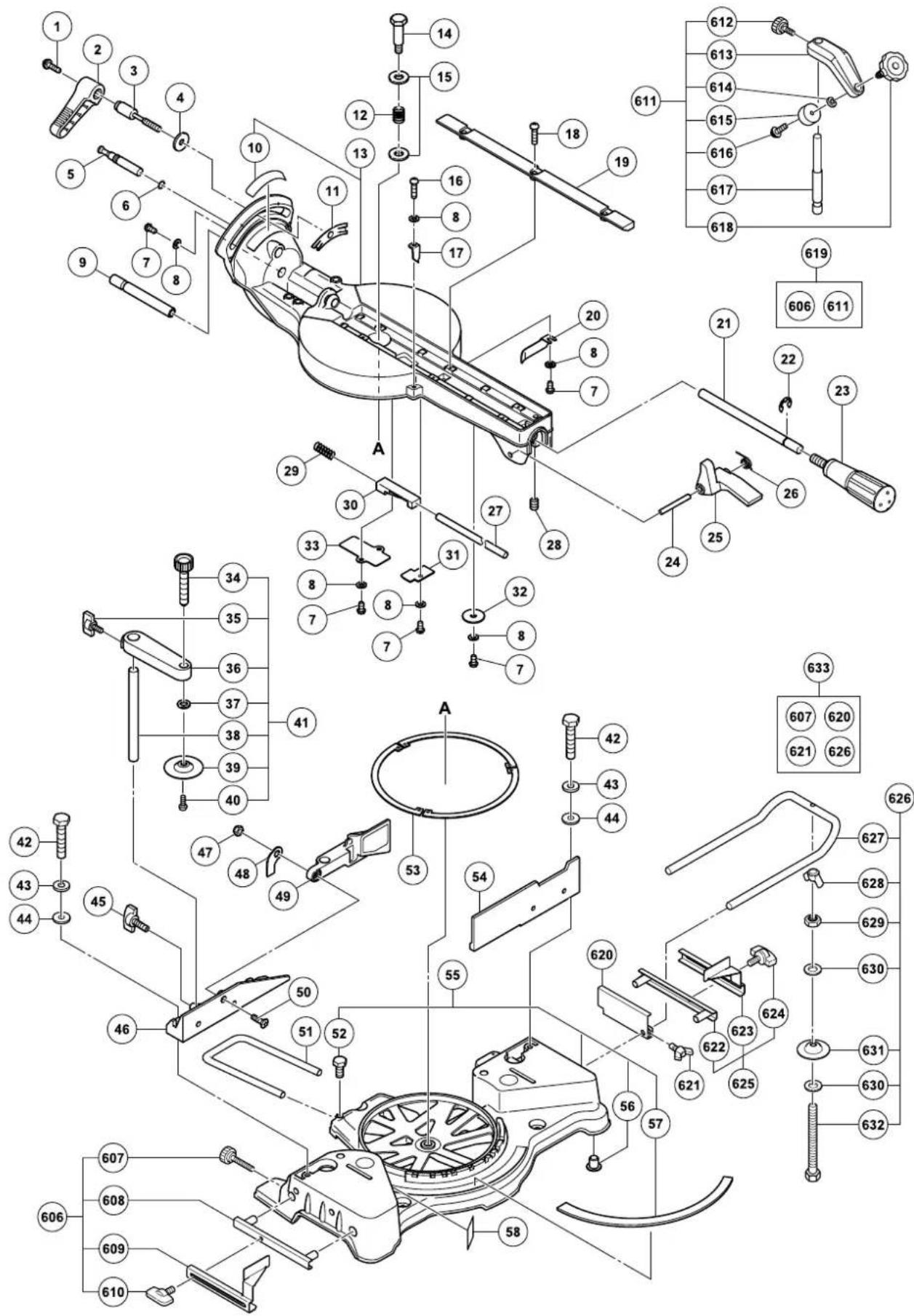
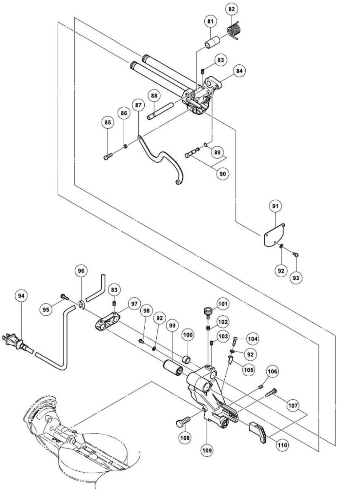
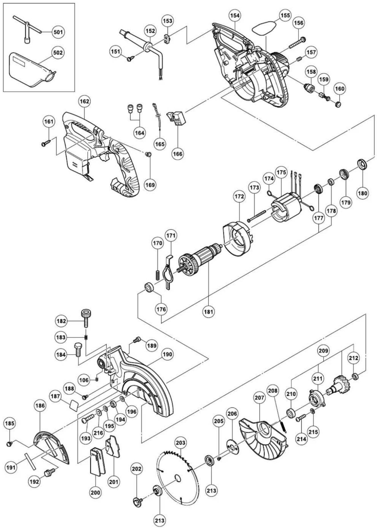
PARTS LIST 84
TABLE DES MATIERES
Français
PAGE
INFORMATIONS IMPORTANTES DE SÉCURITÉ ...... 29
SIGNIFICATION DES MOTS D'AVERTISSEMENT ...... 29
SECURITE 29
CONSIGNES DE SECURITE RELATIVES AUX OUTILS ÉLECTRIQUES 29
PIECES DE RECHANGE .... 33
UTILISER LE CORDON DE RALLONGE APPROPRIÉ .... 33
DOUBLE ISOLATION POUR UN FONCTIONNEMENT PLUS SUR .... 33
UTILISATION ET ENTRETIEN 35
NOM DES PIÈCES 35
PAGE
SPÉCIFICATIONS 36
ACCESSOIRES 37
APPLICATIONS 37
PRÉPARATION AVANT L'UTILISATION .... 38
APPLICATIONS PRATIQUES 45
INSTALLATION ET RETRAIT DE LA LAME ..... 53
ENTRETIEN ET INSPECTION 54
SERVICE APRÈS-VENTE ET RÉPARATIONS ..... 55
LISTE DES PIECES 84
ÍNDICE
Español
PÁGINA
IMPORTANT SAFETY INFORMATION
Read and understand all of the safety precautions, warnings and operating instructions in the Instruction Manual before operating or maintaining this power tool.
Most accidents that result from power tool operation and maintenance are caused by the failure to observe basic safety rules or precautions. An accident can often be avoided by recognizing a potentially hazardous situation before it occurs, and by observing appropriate safety procedures.
Basic safety precautions are outlined in the "SAFETY" section of this Instruction Manual and in the sections which contain the operation and maintenance instructions.
Hazards that must be avoided to prevent bodily injury or machine damage are identified by WARNINGS on the power tool and in this Instruction Manual.
NEVER use this power tool in a manner that has not been specifically recommended by HITACHI.
MEANINGS OF SIGNAL WORDS
WARNING indicates a potentially hazardous situations which, if ignored, could result in death or serious injury.
CAUTION indicates a potentially hazardous situations which, if not avoided, may result in minor or moderate injury, or may cause machine damage.
NOTE emphasizes essential information.
SAFETY
IMPORTANT SAFETY INSTRUCTIONS FOR USING ALL POWER TOOLS
READ ALL OF THE WARNINGS AND OPERATING INSTRUCTIONS IN THIS MANUAL BEFORE OPERATING OR MAINTAINING THIS TOOL:
⚠ WARNING: When using this electric tool, take all necessary precautions to minimize the risk of electric shock or other personal injury. In particular, always comply with the following safety rules:
- ALWAYS KEEP GUARDS IN PLACE and in working order.
- ALWAYS REMOVE ADJUSTING KEYS AND WRENCHES BEFORE STARTING TOOL.
Always confirm that all keys and adjusting wrenches have been removed from the tool before it is turned on. - ALWAYS KEEP WORK AREA CLEAN. Avoid injuries by not cluttering the work areas and work benches.
- NEVER USE TOOL IN HAZARDOUS ENVIRONMENTS. Never use the power tool in damp or wet places and never expose it to rain. Always keep the work area well lighted.
- NEVER PERMIT CHILDREN OR OTHERS TO LOITER NEAR THE WORK AREA. Keep all people (especially children) away from the work area. Always unplug unattended tools and keep the work place tamper-proof by installing locks on the doors and on the master switches. Always remove the lock-off button from the tool and store it in a secure place, when the tool is not in use.
- NEVER FORCE THE TOOL. It will do the job better and more safely if it is operated at the rate for which it was designed.
- ALWAYS USE THE RIGHT TOOLS. Never force a tool or an attachment to do a job for which it was not designed.
-
ALWAYS WEAR PROPER APPAREL WHEN WORKING WITH THE TOOL. Never wear loose clothing, gloves, neckties, rings, bracelets or other jewelry which may get caught in the moving parts. Always wear non-slip footwear, preferably with steel toes. Wear protective hair covering to contain long hair.
-
ALWAYS USE EYE PROTECTION WHEN WORKING WITH THE TOOL TO PREVENT EYE INJURY. Ordinary eyeglasses do not provide adequate protection because the lenses are not made of safety glass. Also, use a face mask for additional safety and wear a dust mask if the cutting operation produces dust.
- ALWAYS SECURE THE WORKPIECE TO THE FENCE OR THE TABLE. Use clamps or a vise to hold the workpiece in place. It is safer than using your hand and it frees both hands to operate the tool.
- NEVER OVERREACH. Always keep proper footing and balance when working with the tool.
- ALWAYS MAINTAIN TOOLS WITH CARE. Always keep tools sharp and clean for the best and safest performance. Always follow instructions for lubricating the tool and for changing accessories.
- ALWAYS DISCONNECT THE TOOL before servicing and before changing blades or other accessories.
- NEVER RISK UNINTENTIONAL STARTING WHEN PLUGGING IN THE TOOL. Always confirm that the switch is in the OFF position before inserting the power plug into the receptacle.
- ALWAYS USE RECOMMENDED ACCESSORIES ONLY WHEN OPERATING THIS TOOL. Consult this instruction manual for descriptions of recommended accessories. To avoid personal injuries, use only recommended accessories in conjunction with this tool.
- NEVER STAND ON THE TOOL. Prevent serious injury by not tipping the tool and by not risking unintentional contact with the saw blade.
- ALWAYS CHECK FOR DAMAGED PARTS BEFORE USING THE TOOL. Always check the guard and all other components for damage before using the tool to assure that they will function properly. Check all moving parts for proper alignment, freedom from binding and other conditions that might affect proper operation. Always repair or replace any damaged guards or other damaged components before using the tool.
- ALWAYS CONFIRM THE ROTATION DIRECTION OF THE BLADE BEFORE USING THE TOOL. Always feed work into the tool against the rotation direction of the blade in order to prevent possible injury.
- NEVER LEAVE THE TOOL RUNNING WHILE UNATTENDED. TURN POWER OFF. Do not leave tool until it comes to a complete stop. Always turn the power off when the tool is not in use. Always unplug the power cord when the tool is not in use.
- This tool was not designed to be used for mass-production applications and should not be used in mass-production environments.
- When servicing this tool, use only authorized replacement parts.
- Apply 120 volts AC only to this tool. Applying the wrong voltage or applying DC power can cause the POWER TOOL to operate improperly and cause serious personal injury or damage to the tool.
- Never raise the saw blade from the workpiece until it has first come to a complete stop.
- Always use outboard stands to provide support for long workpieces that overhang the table of the slide compound miter saw.
- Always return the carriage to the full rear position after each crosscut operation in order to reduce the risk of injury.
- POLARIZED PLUGS To reduce the risk of electric shock, this equipment has a polarized plug (one blade is wider than the other). This plug will fit in a polarized outlet only one way. If the plug does not fit fully in the outlet, reverse the plug. If it still does not fit, contact a qualified electrician to install the proper outlet. Do not change the plug in any way.
Specific Safety Rules for Use of this Power Tool
⚠ WARNING: The following specific operating instructions must be observed when using this POWER TOOL in order to avoid injury:
DO's
ALWAYS OBSERVE THE FOLLOWING RULES TO ASSURE SAFE USE OF THIS TOOL:
- Review this Manual and familiarize yourself with the safety rules and operating instructions for this POWER TOOL before attempting to use it.
-
Always confirm that the POWER TOOL is clean before using it.
-
Always wear snug-fitting clothing, non-skid footwear (preferably with steel toes) and eye protection when operating the POWER TOOL.
- Always handle the POWER TOOL carefully. If the POWER TOOL falls or strikes against a hard object, it might become deformed or cracked or sustain other damage.
- Always cease operating the saw at once, if you notice any abnormality whatsoever.
- Always confirm that all components are mounted properly and securely before using the tool.
- When replacing the saw blade, always confirm that the rpm rating of the new blade is correct for use on this tool.
- Always shut off the power and wait for the saw blade to completely stop rotating before doing any maintenance or adjustments.
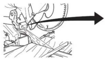
- During slide cutting, always push the saw blade away from the operator.
- Always clamp or otherwise secure the workpiece to the fence; otherwise the workpiece might be thrust form the table and cause bodily harm.
- During miter or bevel cutting, always wait for the rotation of the blade to stop completely before lifting the saw blade.
- Always make a trial run first before attempting any new use of the saw.
- Always handle the saw blade with care when dismounting and mounting it.
- Always confirm that the workpiece is free of nails or other foreign objects before beginning a cut.
- Always keep your hands out of the path of the saw blade.
- Always confirm that the safety cover is in the proper place before using the saw.
- Always confirm that the safety cover does not obstruct the sliding motion of the saw before attempting slide cutting.
- Inspect the tool power cords periodically.
- Always confirm that the proper lengths and types of extension cords are being utilized, if necessary, before starting the tool.
- Always confirm that the motor air vents are fully open before using the tool.
- Always wait until the motor has reached full speed before starting a cut.
- Always keep the handles dry, clean and free of oil and grease. Hold the tool firmly when in use.
- Always use outboard stands to provide support for long workpieces that overhang the table of the slide compound miter saw.
- Always operate the tool after ensuring the workpiece is fixed properly with a vise assembly.
- The operating instructions provided with the tool shall direct the user to secure the tool to supporting structure if, during normal operation, there is a tendency for the tool to tip over, slide, or walk on the supporting surface.
DON'Ts
NEVER VIOLATE THE FOLLOWING RULES TO ASSURE SAFE USE OF THIS TOOL:
- Never operate the POWER TOOL unless you fully understand the operating instructions contained in this Manual.
- Never leave the POWER TOOL unattended without first unplugging the power cord.
- Never operate the POWER TOOL when you are tired, after you have taken any medications, or have consumed any alcoholic beverages.
- Never use the POWER TOOL for applications not specified in the instruction manual.
- Never operate the tool while wearing loose clothing, a necktie or jewelry, or while your hair is uncovered, to protect against getting caught in the moving machinery.
- Never reach around the saw blade.
- Never touch any moving parts, including the blade, while the saw is in use.
-
Never remove any safety devices or blade guards; use of the tool without them would be hazardous.
-
Never lock the safety cover; always confirm that it slides smoothly before using the tool.
- Never damage the power cord of the tool.
- Never attempt to move a plugged-in POWER TOOL while your finger is on the starting switch.
- Never use the POWER TOOL if the starting switch does not turn on and off properly.
- Never use the POWER TOOL if the plastic housing or the handle is cracked or deformed.
- Never use the POWER TOOL near flammable liquids or gases because sparking can cause an explosion.
- Never clean plastic components with solvents because the plastic may dissolve.
- Never operate the saw unless all the blade guards are in place.
- Never raise the saw blade from the workpiece until it has first come to a complete stop.
- When slide cutting, never pull the handle toward the operator, since this could cause the saw blade to kick up from the workpiece. Always push the handle away from the operator in a single, smooth motion.
- Never place your limbs inside of the line next to warning sign " Ⓤ" while the tool is being operated. This may cause hazardous conditions.
- Never use abrasive type blades on this saw.
- Never expose to rain or use in damp locations.
- Never cut ferrous metals or masonry.
WARNING
FOR YOUR OWN SAFETY READ THIS INSTRUCTION MANUAL BEFORE OPERATING THE SLIDE COMPOUND MITER SAW
- Always wear eye protection when using the slide compound miter saw.
- Always keep hands out of the path of the saw blade.
- Never operate the saw without the guards in place.
- Never perform any freehand operation with the slide compound miter saw.
- Never reach around the saw blade.
- Always turn off tool and wait for saw blade to stop before moving workpiece or changing settings.
- Always disconnect power before changing blade or servicing.
- Saw blade diameter is 8-1/2" (216mm).
- No load speed is 5,500/min.
- To reduce the risk of injury, return carriage to the full rear position after each crosscut operation.
REPLACEMENT PARTS
When servicing use only identical replacement parts.
Repairs should be conducted only by a Hitachi authorized service center.
USE PROPER EXTENSION CORD
Make sure your extension cord is in good condition. When using an extension cord, be sure to use one heavy enough to carry the current your product will draw. An undersized cord will cause a drop in line voltage resulting in loss of power and overheating. Table shows the correct size to use depending on cord length and nameplate ampere rating. If in doubt, use the next heavier gage. The smaller the gage number, the heavier the cord.
MINIMUM GAGE FOR CORD SETS
| Total Length of Cord in Feet (Meter) | ||
| 0 – 25 26 – 50 51 – 100 101 – 150(0 – 7.6) (7.9 – 15.2) (15.5 – 30.5) (30.8 – 45.7) | ||
| Ampere Rating AWGMore Not MoreThan Than | ||
| 0 – 6 18 16 16 14 | ||
| 6 – 10 | 18 16 14 12 | |
| 10 – 12 | 16 16 14 12 | |
| 12 – 16 | 14 12 | Not Recommended |

WARNING: Avoid electrical shock hazard. Never use this tool with a damaged or frayed electrical cord or extension cord.
Inspect all electrical cords regularly. Never use in or near water or in any environment where electric shock is possible.
To ensure safer operation of this power tool, HITACHI has adopted a double insulation design. "Double insulation" means that two physically separated insulation systems have been used to insulate the electrically conductive materials connected to the power supply from the outer frame handled by the operator. Therefore, either the symbol "☐" or the words and "Double insulation" appear on the power tool or on the nameplate. Although this system has no external grounding, you must still follow the normal electrical safety precautions given in this Instruction Manual, including not using the power tool in wet environments.
To keep the double insulation system effective, follow these precautions:
* Only HITACHI AUTHORIZED SERVICE CENTER should disassemble or assemble this power tool, and only genuine HITACHI replacement parts should be installed.
* Clean the exterior of the power tool only with a soft cloth moistened with soapy water and dry thoroughly.
* Never use solvents, gasoline or thinners on plastic components; otherwise the plastic may dissolve.
SAVE THESE INSTRUCTIONS
AND
MAKE THEM AVAILABLE TO
OTHER USERS
AND
OWNERS OF THIS TOOL!
NOTE: The information contained in this Instruction Manual is designed to assist you in the safe operation and maintenance of the power tool. Some illustrations in this Instruction Manual may show details or attachments that differ from those on your own power tool.
NAME OF PARTS
Fig. 1
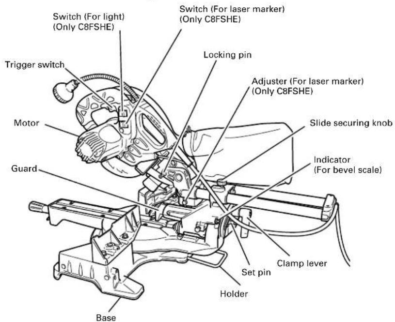
Fig. 2
SPECIFICATIONS
| Item Model C8FSHE / C8FSE | ||||||
| Motor Type Series commutator motor | ||||||
| Power source Single-phase AC 60Hz | ||||||
| Voltage (Volts) 120 | ||||||
| Full-load current (Amp) 9.2 | ||||||
| Laser Marker Maximum output <1mW CLASS II Laser Product(Only Model Wave length 400~700 nmC10FSH) Laser medium Laser Diode | ||||||
| Applicable Outside Dia. 8-1/2" (216mm)saw blade Hole Dia. 5/8" (15.9mm) | ||||||
| No load speed 5,500/min | ||||||
| Max.sawing dimension | Miter | Head | Turntable | Max. sawing dimension | ||
| 0 | 0 | Max. HeightMax. Widthor* Max. HeightMax. WidthWith aux. board | 2-9/16"12-1/4"2-15/16"10-5/6"1-3/16" | (65mm)(312mm)(75mm)(262mm)(30mm) | ||
| 0 | Left 45° or Right 45° | Max. HeightMax. Widthor* Max. HeightMax. WidthWith aux. board | 2-9/16"8-21/32"2-15/16"7-1/4"13/16" | (65mm)(220mm)(75mm)(185mm)(20mm) | ||
| 0 | Right 57° | Max. HeightMax. Widthor* Max. HeightMax. WidthWith aux. board | 2-9/16"6-11/16"2-15/16"5-1/2"13/16" | (65mm)(170mm)(75mm)(140mm)(20mm) | ||
| Bevel | Left 45° | 0 | Max. HeightMax. Widthor* Max. HeightMax. WidthWith aux. board | 1-25/32"12-1/4"1-15/16"9-15/16"1-3/16" | (45mm)(312mm)(50mm)(252mm)(30mm) | |
| Right 5° | 0 | Max. HeightMax. Widthor* Max. HeightMax. WidthWith aux. board | 2-3/8"12-1/4"2-3/4"9-15/16"1-3/16" | (60mm)(312mm)(70mm)(252mm)(30mm) | ||
| Compound | Left 45° | Left 45° or Right 45° | Max. HeightMax. Widthor* Max. HeightMax. WidthWith aux. board | 1-25/32"8-21/32"1-15/16"6-11/16"1-3/16" | (45mm)(220mm)(50mm)(170mm)(30mm) | |
| Right 5° | Left 45° or Right 45° | Max. HeightMax. Widthor* Max. HeightMax. WidthWith aux. board | 2-3/8"8-21/32"2-3/4"6-11/16"1-3/16" | (60mm)(220mm)(70mm)(170mm)(30mm) | ||
| Miter sawing range | Left 0° - 45° Right 0° - 57° | |||||
| Bevel sawing range | Left 0° - 48° Right 0° - 5° | |||||
| Compound sawing range | Left (Bevel) 0° - 45°, Left and Right (Miter) 0° - 45° | |||||
| Right (Bevel) 0° - 5°, Left and Right (Miter) 0° - 45° | ||||||
| Net weight | C8FSHE 32 lbs. (14.5kg) / C8FSE 31 lbs. (14kg) | |||||
| Cord | 2 Conductor type cable 6ft. (1.8m) | |||||
When cutting the workpiece which has the dimension of “*” there might be some possibility of the lower end of the circular saw to touch with the workpiece, even if the motor head is located at the lower limit position. Pay attention when cutting the workpiece. For further details, refer to “PRACTICAL APPLICATIONS” on page 18. Mount the auxiliary board on the fence surface (Refer () the thickness of auxiliary board). Refer to "5. Cutting large workpieces" on page 20 (Fig. 27).
ACCESSORIES

WARNING: Accessories for this power tool are mentioned in this Instruction Manual.
The use of any other attachment or accessory can be dangerous and could cause injury or mechanical damage.
STANDARD ACCESSORIES
| ① 8-1/2" (216mm) TCT Saw blade (1 piece) No. of teeth 24 Code No. 998840 (C330274) | ② Dust bag (1 piece) For how to use, refer to page 25. | ④10mm BOX wrench (1 piece) | ⑥Side handle (1 piece) |
| ③Vise Assembly w/knob bolt (1 piece) For how to use, refer to page 18. | ⑤Holder (1 piece) For how to use, refer to page 15. |
Fig. 3
OPTIONAL ACCESSORIES...sold separately
①Extension Holder and Stopper (Code No. 321553)
②Saw blade 8-1/2" (216mm) TCT Saw blade (Total teeth: 36) (Code No. 998860)
③Saw blade 8-1/2" (216mm) TCT Saw blade (Total teeth:60) (Code No.998862)
④ Saw blade 8-1/2" (216mm) TCT Saw Blade for aluminum (Total teeth: 60) (Code No.998864)
⑤ Crown molding Vise Ass'y (Code No. 329782) (Include Crown molding Stopper (L))
⑥ Crown molding Stopper (L) (Code No. 321374)
⑦ Crown molding Stopper (R) (Code No. 321373)
NOTE: Accessories are subject to change without any obligation on the part of the HITACHI.
APPLICATIONS
Wood and aluminum sash.
Make the following preparations before operating the power tool:
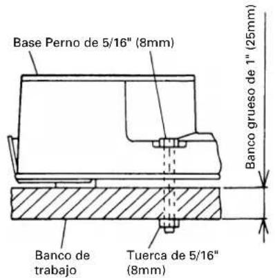
1. Installation
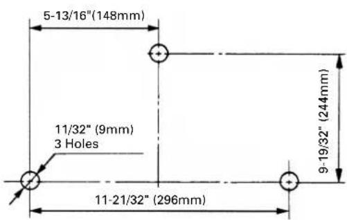
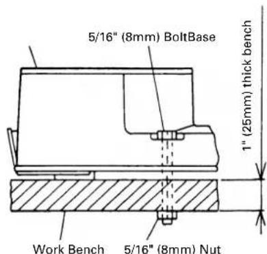
Fig. 4
Attach the power tool to a level, horizontal work bench in accordance with Fig. 4. Select 5/16" (8mm) diameter bolts suitable in length for the thickness of the work bench. Bolt length should be at least 1-9/16" (40mm) plus the thickness of the work bench. For example, use 2-9/16" (65mm) or larger bolts for a 1" (25mm) thick work bench. The holder attached to the rear of the base helps stabilize the power tool.
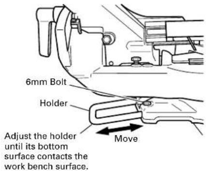
Holder adjustment:
Loosen the 6mm bolt with the supplied 10mm box wrench. Adjust the holder until its bottom surface contacts the work bench surface. After adjustment, firmly tighten the 6mm bolt.
Fig. 5
2. Install the side handle (Fig. 6)
Install the side handle that came enclosed with this unit.
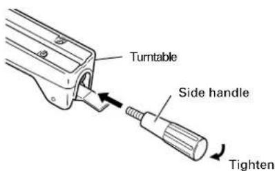
Fig. 6
3. Releasing the locking pin
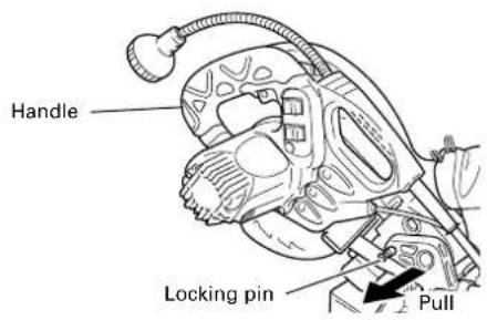
Fig. 7
When the power tool is prepared for shipping, its main parts are secured by a locking pin.
Move the handle slightly so that the locking pin can be disengaged.
NOTE: Lowering the handle slightly will enable you to disengage the locking pin more easily and safely.
The lock position of the locking pin is for carrying and storage only.
4. Installing the dust bag, holder, stopper and vises
(The holder and stopper are optional accessories.)
Attach the dust bag and vise assembly as indicated in Fig. 1 and Fig. 2.
BEFORE USING
- Make sure the power source is appropriate for the tool.
⚠ WARNING: Never connect the power tool unless the available AC power source is of the same voltage as that specified on the nameplate of the tool. Never connect this power tool to a DC power source.
- Make sure the trigger switch is turned OFF.
⚠ WARNING: If the power cord is connected to the power source with the trigger switch turned ON the power tool will start suddenly and can cause a serious accident.
- Check the saw blade for visible defects.
Confirm that the saw blade is free of cracks or other visible damage.
- Confirm that the saw blade is attached securely to the power tool.
Using the supplied 10mm box wrench, tighten the bolt on the saw blade spindle to secure the saw blade.
For details, see Fig. 47-a, Fig. 47-b, Fig. 47-c and Fig. 47-d in the section on "SAW BLADE MOUNTING AND DISMOUNTING".
- Check the lower guard for proper operation.
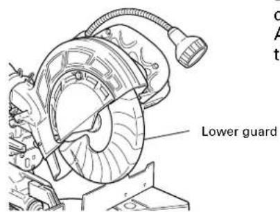
Fig. 8
Lower guard is designed to protect the operator from coming into contact with the saw blade during operation of the tool.
Always check that the lower guard moves smoothly and covers the saw blade properly.
⚠ WARNING: NEVER OPERATE THE POWER TOOL if the safety cover does not function smoothly.
- Confirm the position of the spindle lock before using the tool.
After installing the saw blade, confirm that the spindle lock has been returned to the retract position before using the power tool (see Fig. 47-b).
- Check the lower limit position of the Saw Blade.
Although it was adjusted before shipment, carefully check the height of the saw blade. Confirm that the saw blade can be lowered 13/32" to 7/16" (10mm to 11mm) below the table insert. For details, see the section on "Checking the saw blade lower limit position".
8. Check the Power Receptacle.
To prevent overheating, accidental stopping or intermittent operation, confirm that the power cord plug fits properly in the electrical receptacle and does not fall out after it is inserted. Repair or replace the receptacle if it is faulty.
9. Confirm the tool's power cord is not damaged.
Repair or replace the power cord if an inspection indicates that it is damaged
AFTER CONNECTING THE POWER PLUG TO AN APPROPRIATE AC POWER SOURCE, CHECK THE OPERATION OF THE TOOL AS FOLLOWS:
10. Trial Run
After confirming that no one is standing behind, the power tool start and confirm that no operating abnormalities exist before attempting a cutting operation.
11. Inspect the rotating stability of the saw blade.
For precise cutting, rotate the saw blade and check for deflection to confirm that the blade is not noticeably unstable; otherwise vibrations might occur and cause an accident.
BEFORE CUTTING
1. Positioning the table insert
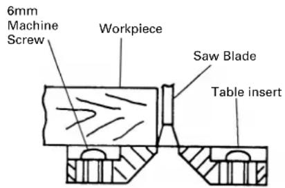
[Right angle cutting] [Left bevel angle cutting] Fig. 9-a Fig. 9-b
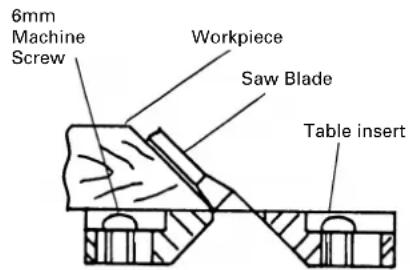
Table inserts are installed on the turntable. When shipping the tool from the factory, the table inserts are so fixed that the saw blade does not contact them. The burr of the bottom surface of the workpiece is remarkably reduced, if the table insert is fixed so that the gap between the side surface of the table insert and the saw blade will be minimum. Before using the tool, eliminate this gap in accordance with the following procedure.
(1) Right angle cutting
Loosen the three 6mm machine screws, then secure the left side table insert and temporarily tighten the 6mm machine screws of both ends. Then fix a workpiece (about 7-7/8" (200mm) wide) with the vise assembly and cut it off. After aligning the cutting surface with the edge of the table insert, securely tighten the 6mm machine screws of both ends. Remove the workpiece and securely tighten the 6mm center machine screw. Adjust the right hand table insert in the same way.
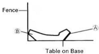
(2) Left bevel angle cutting
Adjust the table insert in the manner shown in Fig. 9-b following the same procedure for right angle cutting.
CAUTION:
After adjusting the table insert for right angle cutting, the table insert will be cut to some extent if it is used for bevel angle cutting.
When bevel cutting operation is required, adjust the table insert for bevel angle cutting.
2. Checking the saw blade lower limit position
Check that the saw blade can be lowered 13/32" to 7/16" (10mm to 11mm) below the table insert as shown in Fig. 10-a.
When you replace a saw blade with a new one, adjust the lower limit position so that the saw blade will not cut the turntable or complete cutting cannot be done.
To adjust the lower limit position of the saw blade, follow the procedures (1) indicated below. (Fig. 10-b)
Furthermore, when changing the position of a 8mm depth adjustment bolt that serves as a lower limit position stopper of the saw blade.
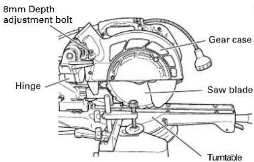
Fig. 10-a
(1) Turn the 8 mm depth adjustment bolt, change the height where the bolt head and the hinge contacts, and adjust the lower limit position of the saw blade.
NOTE: Confirm that the saw blade is adjusted so that it will not cut into the turntable.
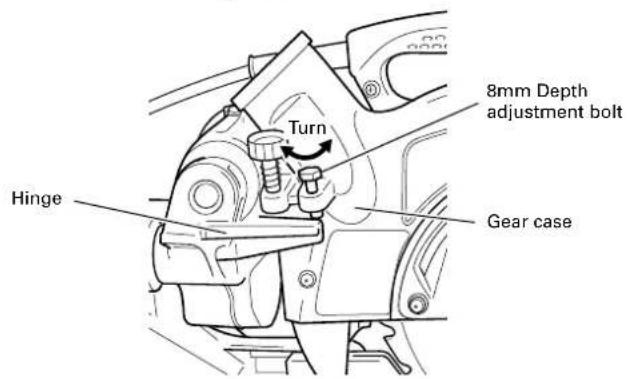
Fig. 10-b
- Lower limit position of saw blade when cutting a large workpiece
NOTE: When cutting a workpiece exceeding 2-9/16" (65mm) in height in right-angle cutting or 1-25/32"(45mm) in left bevel angle cutting or 2-3/8" (60mm) in right bevel angle cutting, adjust the lower limit position so that the base of the motor head (see Fig. 10-a) will not come in contact with the workpiece.
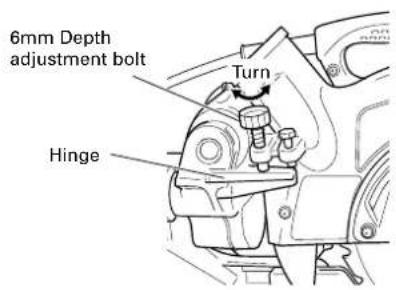
Fig. 11
To adjust the lower limit position of the saw blade, follow the procedure (1) shown in Fig. 11.
(1) Lower the motor head, and turn the 6 mm depth adjustment bolt and make adjustments so that there can be a clearance of 5/64" to 1/8" (2 mm to 3 mm) between the lower limit position of the motor head and the top of the workpiece at the saw blade's lower limit position where the head of the 6 mm depth adjustment bolt contacts the hinge.
- Confirmation for use of sub fence
⚠ WARNING: In the case of left bevel cutting, turn the sub fence counterclockwise. Unless it is turned counterclockwise, the main body or saw blade may contact the sub fence, resulting in an injury.
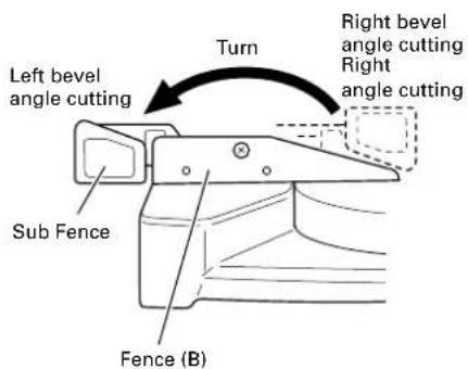
Fig. 12
This power tool is Equipped with a sub fence.
In the case of right angle cutting and right bevel angle cutting, use the sub fence. Then, you can realize stable cutting of the material with a wide back face.
In the case of left bevel cutting, raise the sub fence up as illustrated in Fig. 12 and then turn it counterclockwise.
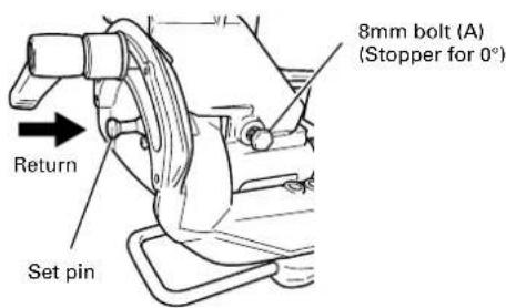
5. Oblique angle
Before the power tool is shipped from the factory, it is adjusted for 0^ , right angle, left 45^ bevel cutting angle with the 8mm bolt (A) and 8mm bolt (B).
When changing the adjustment, change the height of the 8mm bolt (A) or 8mm bolt (B) by turning them.
When changing the bevel angle to the left 45^ and over, pull the set pin on the direction shown in Fig. 13-a and incline the motor head to the left.
When changing the bevel angle to the right, pull the set pin on the direction shown in Fig. 13-a and incline the motor head to the right.
When adjusting the motor head to 0°, always return the set pin to its initial position as shown in Fig. 13-b.
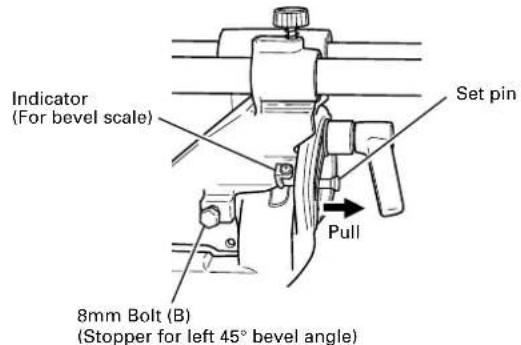
Fig. 13-a Fig. 13-b
6. Securing the workpiece
⚠ WARNING: Always clamp or vise to secure the workpiece to the fence; otherwise the workpiece might be thrust from the table and cause bodily harm.
7. Installing the holders ... (Optional accessory)
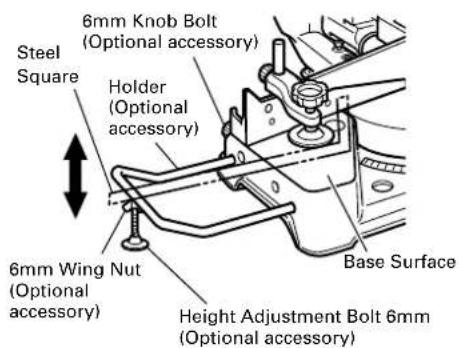
The holders help keep longer workpieces stable and in place during the cutting operation.
(1) As indicated in Fig. 14, use a steel square for aligning the upper edge of the holders with the base surface. Loosen the 6mm wing nut. Turn a height adjustment bolt 6mm, and adjust the height of the holder.
(2) After adjustment, firmly tighten the wing nut and fasten the holder with the 6mm knob bolt (optional accessory). If the length of Height Adjustment Bolt 6mm is insufficient, spread a thin plate beneath. Make sure the end of Height Adjustment Bolt 6mm does not protrude from the holder.
Fig. 14
8. Stopper for precision cutting ... (Stopper and holder are optional accessory)
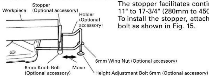
Fig. 15
The stopper facilitates continuous precision cutting in lengths of 11" to 17-3/4" (280mm to 450mm).
To install the stopper, attach it to the holder with the 6mm knob bolt as shown in Fig. 15.
9. Position adjustment of laser line (Only Model C8FSHE)
WARNING: * Make sure before plugging the power plug into the receptacle that the main body and the laser marker are turned off.
* Exercise utmost caution in handling a switch trigger for the position adjustment of the laser line, as the power plug is plugged into the receptacle during operation. If the switch trigger is pulled inadvertently, the saw blade can rotate and result in unexpected accidents.
* Do not remove the laser marker to be used for other purposes.
CAUTION:
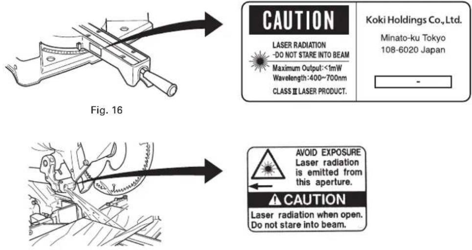
Fig. 17
* Laser radiation- Do not stare into beam.
* Laser radiation on work table. Do not stare into beam.
If your eye is exposed directly to the laser beam, it can be hurt.
* Do not dismantle it.
* Do not give strong impact to the laser marker (main body of tool); otherwise, the position of a laser line can go out of order, resulting in the damage of the laser marker as well as a shortened service life.
* Keep the laser marker lit only during a cutting operation. Prolonged lighting of the laser marker can result in a shortened service life.
* Use of controls or adjustments or performance of procedures other than those specified herein may result in hazardous radiation exposure.
NOTE: * Perform cutting by overlapping the ink line with the laser line.
* When the ink line and the laser line are overlapped, the strength and weakness of light will change, resulting in a stable cutting operation because you can easily discern the conformity of lines. This ensures the minimum cutting errors.
* In outdoor or near-the-window operations, it may become difficult to observe the laser line due to the sunlight. Under such circumstances, move to a place that is not directly under the sunlight and engage in the operation.
* Do not tug on the cord behind the motor head or hook your finger, wood and the like around it; otherwise, the cord may come off and the laser marker may not be lit up.
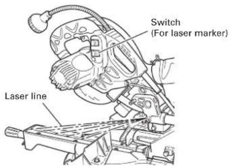
Fig. 18
Ink lining can be easily made on this tool to the laser marker. A switch lights up the laser marker. (Fig. 18)
Depending upon your cutting choice, the laser line can be aligned with the left side of the cutting width (saw blade) or the ink line on the right side.
The laser line is adjusted to the width of the saw blade at the time of factory shipment. Adjust the positions of the saw blade and the laser line taking the following steps to suit the use of your choice.
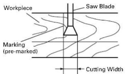
Fig. 19
(1) Light up the laser marker and make a groove of about 3/16" (5mm) deep on the workpiece that is about 25/32" (20mm) in height and 5-29/32"(150mm) in width. Hold the grooved workpiece by vise as it is and do not move it. For grooving work, refer to "11. Groove cutting procedures" on page 24.
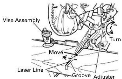
Fig. 20
(2) Then, turn the adjuster and shift the laser line. (If you turn the adjuster clockwise, the laser line will shift to the right and if you turn it counterclockwise, the laser line will shift to the left.) When you work with the ink line aligned with the left side of the saw blade, align the laser line with the left end of the groove. (Fig. 20) When you align it with the right side of the saw blade, align the laser line with the right side of the groove.
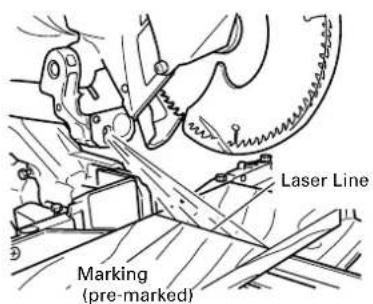
Fig. 21
(3) After adjusting the position of the laser line, draw a right-angle ink line on the workpiece and align the ink line with the laser line. When aligning the ink line, slide the workpiece little by little and secure it by vise at a position where the laser line overlaps with the ink line. Work on the grooving again and check the position of the laser line. If you wish to change the laser line's position, make adjustments again following the steps from (1) to (3).
NOTE: Check and make sure on a periodic basis if the position of the laser line is in order. As regards the checking method, draw a right-angle ink line on the workpiece with the height of about 25/32" (20mm) and the width of 5-29/32"(150mm), and check that the laser line is in line with the ink line [The deviation between the ink line and the laser line should be less than the ink line width (0.5mm)]. (Fig. 21)
PRACTICAL APPLICATIONS
⚠ WARNING: * To avoid personal injury, never remove or place a workpiece on the table while the tool is being operated.
* Never place your limbs inside of the line next to warning sign while the tool is being operated. This may cause hazardous conditions (see Fig. 22).
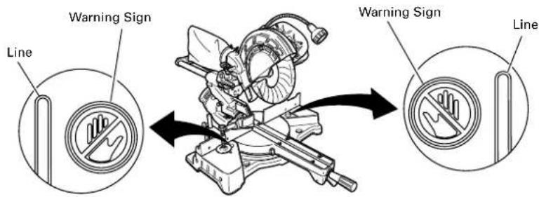
Fig. 22
1. Switch operation
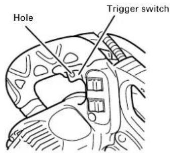
Fig. 23
Pull the trigger to turn on the switch, release it to shut it off. After releasing the trigger, make sure the trigger has gone all the way back and the switch is turned off.
WARNING: This will ensure that the power tool cannot be turned on accidentally or by someone (especially a child) who is not qualified to use the power tool. To prevent unauthorized operation of this tool, insert a padlock through the hole in the switch trigger.
2. Using the Vise Assembly (Standard accessory)
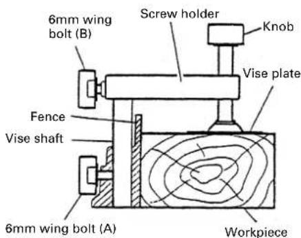
Fig. 24
(1) The vise assembly can be mounted on either the left fence {Fence (B)} or the right fence {Fence (A)} by loosening the 6mm wing bolt (A).
(2) The screw holder can be raised or lowered according to the height of the workpiece by loosening the 6mm wing bolt (B). After the adjustment, firmly tighten the 6mm wing bolt (B) and fix the screw holder.
(3) Turn the upper knob and securely fix the workpiece in position (Fig. 24).
WARNING: Always firmly clamp or vise to secure the workpiece to the fence; otherwise the workpiece might be thrust from the table and cause bodily harm.
CAUTION: Always confirm that the motor head (see Fig. 1) does not contact the vise assembly when it is lowered for cutting. If there is any danger that it may do so, loosen the 6 mm wing bolt (B) and move the vise assembly to a position where it will not contact the saw blade.
3. Cutting Operation
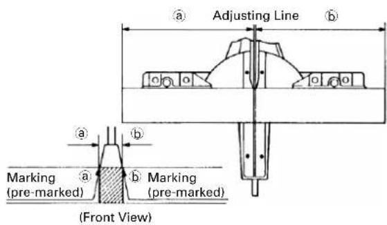
Fig. 25
(1) As shown in Fig. 25 the width of the saw blade is the width of the cut. Therefore, slide the workpiece to the right (viewed from the operator's position) when length is desired, or to the left when length is desired.
(Only Model C8FSHE)
If a laser marker is used, align the laser line with the left side of the saw blade, and then align the ink line with the laser line.
(2) Once the saw blade reaches maximum speed, push the handle down carefully until the saw blade approaches the workpiece.
(3) Once the saw blade contacts the workpiece, push the handle down gradually to cut into the workpiece.
(4) After cutting the workpiece to the desired depth, turn the power tool OFF and let the saw blade stop completely before raising the handle from the workpiece to return it to the full retract position.
CAUTION:
* Increased pressure on the handle will not increase the cutting speed.
On the contrary, too much pressure may result in overload of the motor and/or decreased cutting efficiency.
WARNING:
* Confirm that the trigger switch is turned OFF and the power plug has been removed from the receptacle whenever the tool is not in use.
* Always turn the power off and let the saw blade stop completely before raising the handle from the workpiece.
If the handle is raised while the saw blade is still rotating, the cut-off piece may become jammed against the saw blade causing fragments to scatter about dangerously.
* Every time one cutting or deep-cutting operation is finished, turn the switch off, and check that the saw blade has stopped. Then raise the handle, and return it to the full retract position.
* Be absolutely sure to remove the cut material from the top of the turntable, and then proceed to the next step.
* Continued cutting operation can result in overload of the motor. Touch the motor and if it's hot, stop your cutting operation once and rest for 10 minutes or so, and then restart your cutting operation.
4. Cutting narrow workpieces (Press cutting)
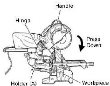
Fig. 26
Slide the hinge down to holder (A), then tighten the slide securing knob (see Fig. 2) as indicated in Fig. 26.
Lower the handle to cut the workpiece.
Using the power tool this way will permit cutting of workpieces of up to 2-9/16" (65mm) square.
5. Cutting large workpieces
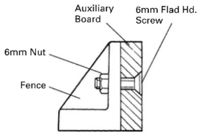
Fig. 27
There may be case when a complete cutting cannot be done depending on the height of workpiece. In this case, mount an auxiliary board with the 6mm flat head screws and the 6mm nuts using the 7mm holes on the fence surface (two holes on each side). (Fig. 27)
Refer to page 9 "SPECIFICATIONS" for the thickness of the auxiliary board.
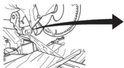
6. Cutting wide workpieces (Slide cutting)
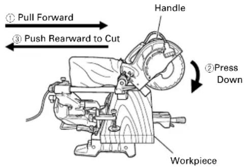
Fig. 28
(1) Workpieces up to 2-9/16" (65mm) high and 12-1/4" (312mm) wide: Loosen the slide securing knob (see Fig. 2), grip the handle and slide the saw blade forward. Then press down on the handle and slide the saw blade back to cut the workpiece as indicated in Fig. 28. This facilitates cutting of workpieces of up to 2-9/16" (65mm) in height and 12-1/4" (312mm) in width.
(2) Workpieces up to 2-15/16" (75mm) high and 10-5/16" (262mm) wide: Workpieces of up to 2-15/16" (75mm) in height and up to 10-5/16" (262mm) in width can be cut in the same manner as described in paragraph 6-(1) above.
CAUTION:
* When cutting a workpiece of 2-9/16" (65mm) height, adjust the lower limit position of the motor head so that the gap between the lower edge of the motor head and the workpiece will be 3/32" to 1/8" (2 to 3mm) at the lower limit position.
* If the handle is pressed down with excessive or lateral force, the saw blade may vibrate during the cutting operation and cause unwanted cutting marks on the workpiece, thus reducing the quality of the cut.
Accordingly, press the handle down gently and carefully.
* In slide cutting, gently push the handle back (rearwards) in a single, smooth operation.
Stopping the handle movement during the cut will cause unwanted cutting marks on the workpiece.
WARNING:
* For slide cutting, follow the procedures indicated above in Fig. 28.
Forward slide cutting (toward the operator) is very dangerous because the saw blade could kick upward from the workpiece. Therefore, always slide the handle away from the operator.
* Always return the carriage to the full rear position after each crosscut operation in order to reduce the risk of injury.
* Never put your hand on the side handle during the cutting operation because the saw blade comes close to the side handle when the motor head is lowered.
7. Bevel cutting procedures
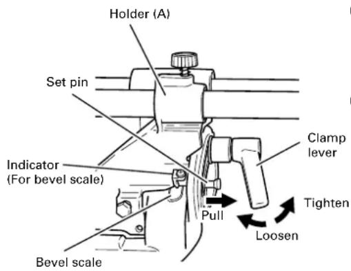
Fig. 29
(1) Loosen the clamp lever and bevel the saw blade to the left or to the right. When tilting the motor head to the right pull the set pin towards the rear.
(2) Adjust the bevel angle to the desired setting while watching the bevel angle scale and indicator, then secure the clamp lever.
(3) Follow the procedures indicated in paragraphs 4,5 and 6 above. For maximum dimensions for bevel cutting, refer to "SPECIFICATIONS" table on page 9.
WARNING:
When the workpiece is secured on the left or right side of the blade, the short cut-off portion will come to rest on the right or left side of the saw blade. Always turn the power off and let the saw blade stop completely before raising the handle from the workpiece.
If the handle is raised while the saw blade is still rotating, the cut-off piece may become jammed against the saw blade causing fragments to scatter about dangerously.
When stopping the bevel cutting operation halfway, start cutting after pulling back the motor head to the initial position.
Starting from halfway, without pulling back, causes the lower guard to be caught in the cutting groove of the workpiece and to contact the saw blade.
CAUTION:
When cutting a workpiece of 1-15/16" (50mm) height in the left 45° bevel cutting position or a workpiece of 2-3/4" (70mm) height in the right 5° bevel cutting position, adjust the lower limit position of the motor head so that the gap between the lower edge of the motor head and the workpiece will be 5/64" to 1/8" (2 to 3mm) at the lower limit position (refer to "2. Checking the saw blade lower limit position" on page 13).
8. Miter cutting procedures
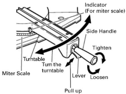
Fig. 30
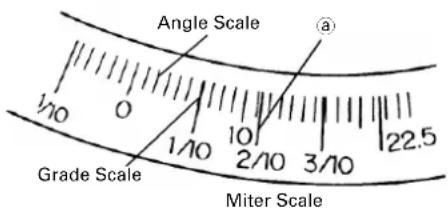
Fig. 31
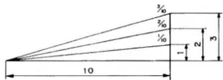
Fig. 32
(1) Loosen the side handle and pull up the lever for angle stoppers. Then, adjust the turntable until the indicator aligns with desired setting on the miter scale (Fig. 30).
(2) Re-tighten the side handle to secure the turntable in the desired position.
(3) The miter scale (Fig. 31) indicates both the cutting angle on the angle scale and the gradient on the grade scale.
(4) The gradient, which is the ratio of the height to the base of the triangular section to be removed, may be used for setting the miter scale instead of the cutting angle, if desired (see Fig. 31).
(5) Therefore, to cut a workpiece at a grade of 2/10, set the indicator to position ⓐ as indicated in Fig. 31.
NOTE: * Positive stops are provided at the right and left of the 0° center setting, at 15°, 22.5°, 31.6° and 45° settings. Check that the miter scale and the tip of the indicator are properly aligned.
* Operation of the saw with the miter scale and indicator out of alignment, or with the side handle not properly tightened, will result in poor cutting precision.
9. Compound cutting procedures
Compound cutting can be performed by following the instructions in 7 and 8 above. For maximum dimensions for compound cutting, refer to "SPECIFICATIONS" table on page 9.
CAUTION:
Always secure the workpiece with the right or left hand and cut it by sliding the round portion of the saw backwards with the left hand.
It is very dangerous to rotate the turntable to the left during compound cutting because the saw blade may come into contact with the hand that is securing the workpiece.
In case of compound cutting (angle + bevel) by left bevel, turn the sub-fence counterclockwise, and engage in the cutting operation.
10. Crown molding cutting procedures
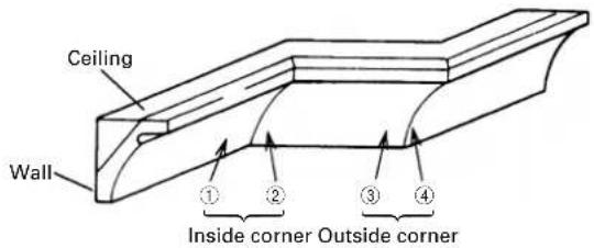
Fig. 33 shows two common crown molding types having angles of (θ) 38^ and 45^ . For the typical crown molding fittings, see Fig. 34.
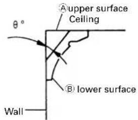
Fig. 33 Fig. 34
The table below shows the miter angle and the bevel angle settings that are ideal for the two crown molding types.
NOTE: For convenience, positive stops are provided for the miter setting (left and right 31.6°) positions.
For miter cut setting
If the turntable has been set to either of the angles described, move the turntable adjusting side handle a little to the right and left to stabilize the position and to properly align the miter angle scale and the tip of the indicator before the operation starts.
For bevel cut setting
Move handle on bevel section to the left and check that the position is stable and that the bevel angle scale and the tip of the indicator are properly aligned. Then tighten the clamp lever.
| Type of Crown Molding | To process crown molding at positions 1 and 4 in Fig. 34. | To process crown molding at positions 2 and 3 in Fig. 34. | ||
| Miter Angle Setting | Bevel Angle Setting | Miter Angle Setting | Bevel Angle Setting | |
| 45° Type | right 35.3°(↓mark) | left 30°(↓mark) | left 35.3°(↓mark) | left 30°(↓mark) |
| 38° Type | right 31.6°(↓mark) | left 33.9°(↓mark) | left 31.6°(↓mark) | left 33.9°(↓mark) |
30^ and 33.9^ left slant setting method
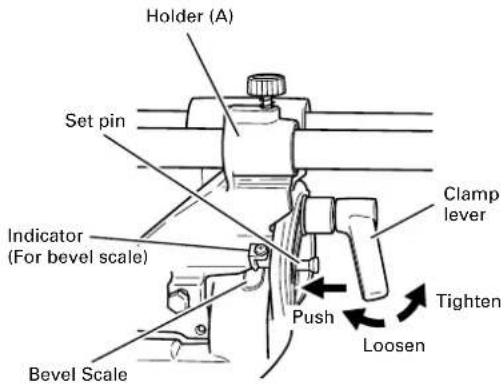
Fig. 35
(1) Loosen the clamp lever and slant to the left a little at a time while pushing the set pin into the main unit. At this time, the fixing pin will enter one step and fit into the 30^ left slant and 33.9^ left slant setting slots.
(2) With the set pin in the slot as described above, setting to the 30^ left slant position is possible by pushing to the right side.
(3) Also, with the set pin in the slot as described above, setting to the 33.9^ left slant position is possible by pushing to the left side.
(4) Look at the bevel scale and indicator to recheck whether or not the settings match and then tighten the clamp lever.
(1) Setting to cut crown moldings at positions ① and ④ in Fig. 34 (see Fig. 36; tilt the motor head to the left):
① Turn the turntable to the right and set the Miter Angle as follows:
* For 45° type crown moldings: 35.3° ( mark)
* For 38° type crown moldings: 31.6° ( mark)
②Tilt the motor head to the left and set the Bevel Angle as follows:
* For 45° type crown moldings: 30° (↓mark)
* For 38° type crown moldings: 33.9° ( mark)
③ Position the crown molding so that the upper surface (A in Fig. 33) contacts the fence as indicated in Fig. 38.
(2) Setting to cut crown moldings at positions ② and ③ in Fig. 34 (see Fig. 37; tilt the head to the left):
① Turn the turntable to the left and set the Miter Angle as follows:
* For 45° type crown moldings: 35.3° ( mark)
* For 38° type crown moldings: 31.6° ( mark)
②Tilt the head to the left and set the Bevel Angle as follows:
* For 45° type crown moldings: 30° (↓mark)
* For 38° type crown moldings: 33.9° ( mark)
③ Position the crown molding so that the lower surface (B in Fig. 33) contacts the fence as in Fig. 39.
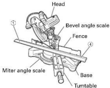
Fig. 36 Fig. 37
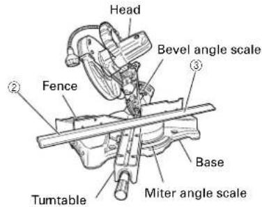
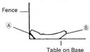
Fig. 38 Fig. 39
Cutting method of crown molding without tilting the saw blade.
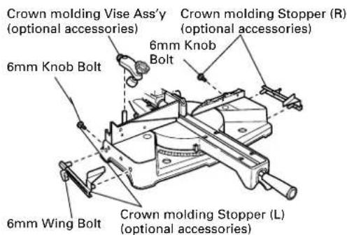
Fig. 40-a
(1) Crown molding Stopper (L) and (R) (optional accessories) allow easier cuts of crown molding without tilting the saw blade. Install them in the base both-sides side to be shown in Fig. 40-a. After inserting Tighten the 6mm knob bolts to secure the crown molding Stoppers.
[Optional accessories used]
- Crown molding Vise Ass'y (Include Crown molding Stopper (L))
• Crown molding Stopper (L)
• Crown molding Stopper (R)
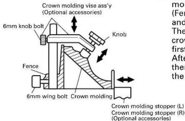
Fig. 40-b
(2) The crown molding vise (B) (Optional accessory) can be mounted on either the left fence (Fence (B)) or the right fence (Fence (A)). It can unite with the slope of the crown molding and vice can be pressed down.
Then turn the upper knob, as necessary, to securely attach the crown molding in position. To raise or lower the vise assembly, first loosen the 6mm knob bolt.
After adjusting the height, firmly tighten the 6mm wing bolt; then turn the upper knob, as necessary, to securely attach the crown molding in position. (see Fig. 40-b)
WARNING: Always firmly clamp or vise to secure the crown molding to the fence; otherwise the crown molding might be thrust from the table and cause bodily harm. Do not bevel cutting. The main body or saw blade may contact the sub fence, resulting in an injury.

CAUTION:
Always confirm that the motor head (see Fig. 1) does not contact the crown molding vise ass'y when it is lowered for cutting. If there is any danger that it may do so, loosen the 6mm knob bolt and move the crown molding vise ass'y to a position where it will not contact the saw blade.
Position crown molding with its WALL CONTACT EDGE against the guide fence and its CEILING CONTACT EDGE against the crown molding Stoppers as shown in Fig. 40-b.
Adjust the crown molding Stoppers according to the size of the crown molding.
Tighten the 6mm wing bolt to secure the crown molding Stoppers.
Refer to the lower table for the miter angle.
| Position in Fig. 34 Miter angle Finished piece | |||
| For inside corner 1Right 45° Save the right side of blade | |||
| Left 45°Save the left side of blade | |||
| For outside corner 3Save the right side of blade | |||
11. Groove cutting procedures
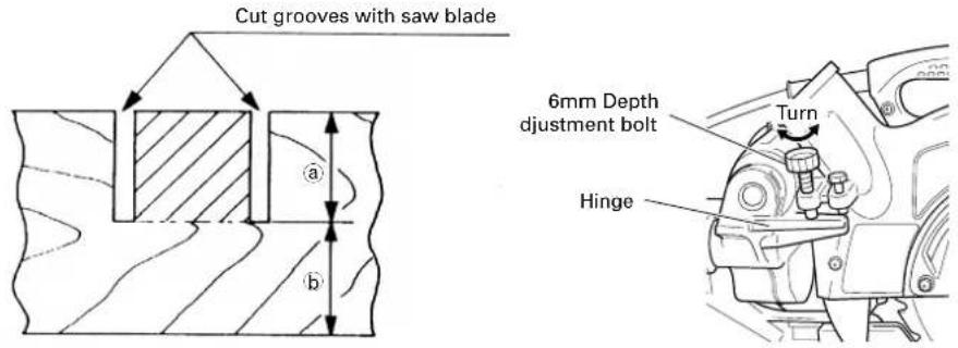
Fig. 41 Fig. 42
Grooves in the workpiece can be cut as indicated in Fig. 41 by adjusting the 6mm depth adjustment bolt.
Cutting depth adjustment procedure:
(1) Lower the motor head, and turn the 6 mm depth adjustment bolt by hand. (Where the head of the 6 mm depth adjustment bolt contacts the hinge.)
(2) Adjust to the desired cutting depth by setting the distance between the saw blade and the surface of the base (see b in Fig. 41).
(3) The 8mm wing nut must be properly tightened after the adjustment has been completed.
NOTE: When cutting a single groove at either end of the workpiece, remove the unneeded portion with a chisel.
12. Using the Light (Only Model C8FSHE)

WARNING:
Check to ascertain that the main unit and light are off before plugging the cord into the power socket.
The light lens reaches high temperatures during and immediately after use and should not be touched under any circumstances.
Failure to observe this may result in burns.
⚠️ CAUTION: Do not subject the light to strong impact.
Failure to observe this may result in damage to the light or a reduced life span.
Only switch the light on when cutting.
Do not shine the light continuously into the eyes.
Failure to observe this may result in damage to the eyes.
Wipe all dirt that adheres to the light lens with a soft cloth gently so that the light is not scratched or damaged.
Scratches on the light lens may result in less luminance.
The light switch is fitted with an anti-dust cover. Make sure that the switch cover is not scratched or otherwise damaged.
There are cases in which shavings may enter the switch and prevent the light from functioning.
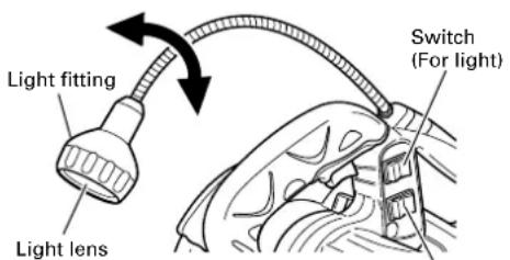
Switch (For laser marker)
(Also serves as light power switch)
Fig. 43
(1) Insert the plug on the main unit into a power socket.
(2) Turning on the laser marker switch.
(3) Set the light switch into the upper position (ON) to light it, and into the lower position (OFF) to switch it off. (See Fig. 43)
(4) Move the light fitting to the right and left to adjust the lighting position.
NOTE: The light will not light up if the laser marker switch is turned off.
13. Cutting easily-deformed materials, such as aluminum sash
Materials such as aluminum sash can easily deform when tightened too much in a vise assembly. This will cause inefficient cutting and possible overload of the motor.
When cutting such materials, use a wood plate to protect the workpiece as shown in Fig. 44. Set the wood plate near the cutting section.
When cutting aluminum materials, coat the saw blade with cutting oil (non-combustible) to achieve smooth cutting and a fine finish.
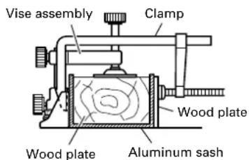
In addition, in case of a U-shaped workpiece, use the wood plate as shown in Fig. 45 to ensure stability in the lateral direction, and clamp it near the cutting section of the workpiece and tighten it using both the vise assembly and the clamp available in the market.
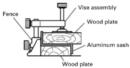
Fig. 44 Fig. 45
14. How to use the dust bag (Standard accessory)
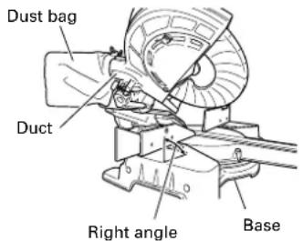
Fig. 46
(1) When the dust bag has become full of sawdust, dust will be blown out of the dust bag when the saw blade rotates.
Check the dust bag periodically and empty it before it becomes full.
(2) During bevel and compound cutting, attach the dust bag at a right angle to the base surface as shown in Fig. 46.
CAUTION: Empty the dust bag frequently to prevent the duct and the lower guard from becoming clogged.
Sawdust will accumulate more quickly than normal during bevel cutting.
SAW BLADE MOUNTING AND DISMOUNTING
⚠ WARNING: *To prevent an accident or personal injury, always turn off the trigger switch and disconnect the power plug from the receptacle before removing or installing a saw blade.
If cutting work is done in a state where the bolt is not sufficiently tightened, the bolt can get loose, the blade can come off, and the lower guard can get damaged, resulting in injuries.
Also, check that the bolts are properly tightened before plugging the power plug into the receptacle.
*If the bolts are attached or detached using tools other than the 10mm box wrench (standard accessory), excessive or improperly tightening occurs, resulting in injury.
- Mounting the saw blade (Fig. 47-a, Fig. 47-b, Fig. 47-c and Fig. 47-d)
(1) Use the accessory 10mm box wrench to loosen the 6mm bolt fastening the spindle cover and then remove the spindle cover.
(2) Press in spindle lock and loosen bolt with 10mm box wrench (standard accessory). Since the bolt is left-hand threaded, loosen by turning it to the right as shown in Fig. 47-c.
NOTE: If the spindle lock cannot be easily pressed in to lock the spindle, turn the bolt with 10mm box wrench (standard accessory) while applying pressure on the spindle lock. The saw blade spindle is locked when the spindle lock is pressed inward.
(3) Remove the bolt and washer (D)
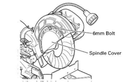
Fig. 47-a Fig. 47-b

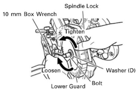
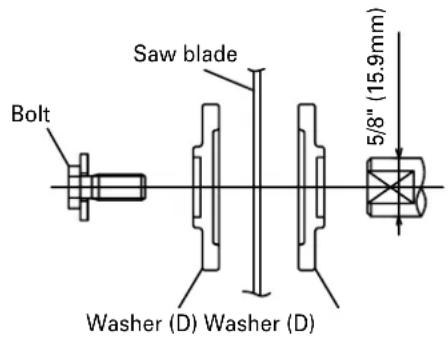
Fig. 47-c Fig. 47-d
(4) Lift the lower guard and mount the saw blade.
⚠ WARNING: When mounting the saw blade, confirm that the rotation indicator mark on the saw blade and the rotation direction of the gear case(see Fig. 1) are properly matched.
(5) Thoroughly clean washer (D) and the bolt, and install them onto the saw blade spindle.
(6) Press in the spindle lock and tighten the bolt by turning it to the left by standard accessorie's wrench (10mm box wrench) as indicated in Fig. 47-c.
⚠️ CAUTION: *A dust guide is installed inside behind the gear case.
When removing or installing the saw blade, do not make contact with the dust guide. Contact may break or chip saw blade tips.
* Confirm that the spindle lock has returned to the retract position after installing or removing the saw blade.
* Tighten the bolt so it does not come loose during operation. Confirm the bolt has been properly tightened before the power tool is started.
2. Dismounting the saw blade
Dismount the saw blade by reversing the mounting procedures described in paragraph 1 above.
The saw blade can easily be removed after lifting the lower guard.

CAUTION: Never attempt to install saw blades larger than 8-1/2" (216mm) in diameter.
Always install saw blades that are 8-1/2" (216mm) in diameter or less.
MAINTENANCE AND INSPECTION

WARNING: To avoid an accident or personal injury, always confirm that the trigger switch is turned OFF and the power plug has been disconnected from the receptacle before performing any maintenance or inspection of this tool.
1. Inspecting the saw blade
Always replace the saw blade immediately upon the first sign of deterioration or damage.
A damaged saw blade can cause personal injury and a worn saw blade can cause ineffective operation and possible overload to the motor.

CAUTION: Never use a dull saw blade. When a saw blade is dull, its resistance to the hand pressure applied by the tool handle tends to increase, making it unsafe to operate the power tool.
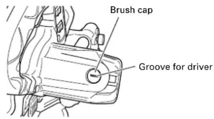
2. Inspecting the carbon brushes (Fig. 48 and Fig. 49)
The carbon brushes in the motor are expendable parts.
If the carbon brushes become excessively worn, motor trouble might occur.
Therefore, inspect the carbon brushes periodically and replace them when they have become worn to the wear limit line as shown in Fig. 48.
Also, keep the carbon brushes clean so that they will slide smoothly within the brush holders.
The carbon brushes can easily be removed after removal of the brush caps (see Fig. 49) with a slotted (minus) screwdriver.

Fig. 48 Fig. 49
3. About Handling the Motor (see Fig. 1)
Winding of the motor is said to be the heart of this tool. Exercise utmost caution not to damage the winding by exposing it to wash oil or water.
NOTE: Accumulation of dust and the like inside the motor can result in a malfunction.
After using the motor for 50 hours or so, carry out no-load running, and blow in the dry air from a wind hole at the motor's rear. Such action is effective to discharge dust and the like.
4. Inspecting the screws
Regularly inspect each component of the power tool for looseness.
Re-tighten screws on any loose part.

WARNING: To prevent personal injury, never operate the power tool if any components are loose.
5. Inspecting the lower guard for proper operation
Before each use of the tool, test the lower guard (see Fig. 8) to assure that it is in good condition and that it moves smoothly.
Never use the tool unless the lower guard operates properly and it is in good mechanical condition.
6. Storage
After operation of the tool has been completed, check that the following has been performed:
(1) Trigger switch is in OFF position,
(2) Power plug has been removed from the receptacle,
When the tool is not in use, keep it stored in a dry place out of the reach of children.
7. Lubrication
Lubricate the following sliding surfaces once a month to keep the power tool in good operating condition for a long time (see Fig. 1 and Fig. 2). Use of machine oil is recommended.
Oil supply points:
* Rotary portion of hinge
* Rotary portion of vise assembly
* Rotary portion of holder (A)
8. Cleaning
Periodically remove chips, dust and other waste material from the surface of the power tool, especially from the inside of the lower guard with a damp, soapy cloth. To avoid a malfunction of the motor, protect it from contact with oil or water.
(Only Model C8FSHE)
If the laser line becomes invisible due to chips and the like adhered onto the window of the laser marker's light-emitting section, wipe and clean the window with a dry cloth or a soft cloth moistened with soapy water, etc.
SERVICE AND REPAIRS
All quality power tools will eventually require servicing or replacement of parts because of wear from normal use. To assure that only authorized replacement parts will be used and that the double insulation system will be protected, all service (other than routine maintenance) must be performed by an AUTHORIZED HITACHI POWER TOOL REPAIR CENTER ONLY.
NOTE: Specifications are subject to change without any obligation on the part of HITACHI.
INFORMATIONS IMPORTANTES DE SÉCURITÉ
CHOSES A NE PAS FAIRE
POUR GARANTIR UNE UTILISATION EN TOUTE SÉCURITÉ, NE JAMAIS VIOLER LES CONSIGNES SUIVANTES:
natural_image
Technical line drawing of a mechanical clamp or bracket with a curved arrow indicating direction (no text or symbols)Fig. 16

natural_image
Technical line drawing of mechanical assembly with tool and component (no text or symbols)
Fig. 17
APPLICATIONS PRATIQUES
⚠ AVERTISSEMENT:
Fig. 32
natural_image
Technical line drawing of a mechanical clamp or lever assembly with an arrow indicating direction (no text or symbols present)Fig. 16

natural_image
Technical line drawing of mechanical assembly with tool and component (no text or symbols)
Fig. 17
Esquina interior Esquina exterior
C8FSHE
C8FSHE
C8FSHE
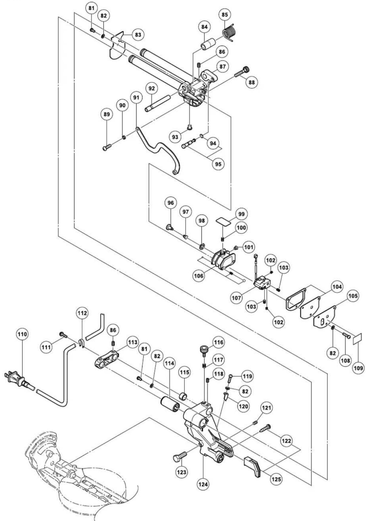
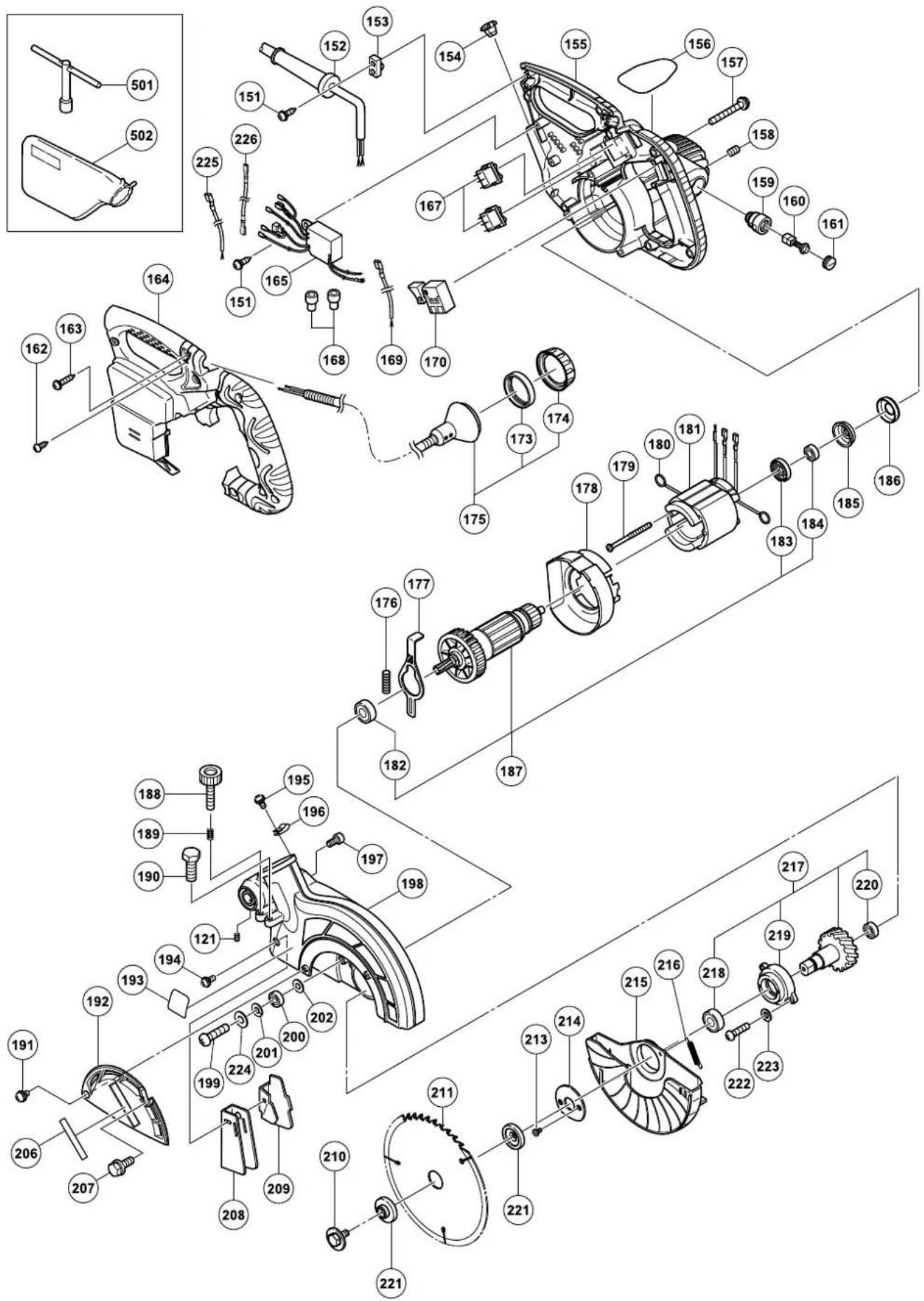
| ITEMNO. | PART NAME | Q'TY |
| 1 | MACHINE SCREW (W/WASHERS) M4 × 12 | 1 |
| 2 CLAMP LEVER 1 | ||
| 3 BOLT (LEFT HAND) D10 1 | ||
| 4 SPECIAL WASHER 1 | ||
| 5 SET PIN 1 | ||
| 6 O-RING (1AP-12) 1 | ||
| 7 | MACHINE SCREW M4 × 8 | 5 |
| 8 BOLT WASHER M4 6 | ||
| 9 HINGE SHAFT (A) 1 | ||
| 10 SCALE (B) 1 | ||
| 11 LINER (A) 1 | ||
| 12 SPRING 1 | ||
| 13 TURN TABLE ASS'Y 1 | ||
| 14 SHAFT (B) | ||
| 15 BOLT WASHER M12 2 | ||
| 16 | MACHINE SCREW M4 × 12 | 1 |
| 17 INDICATOR | ||
| 18 | MACHINE SCREW M6 × 16 | 6 |
| 19 TABLE INSERT | ||
| 20 SPACER (A) | ||
| 21 SHAFT (A) | ||
| 22 E-RING | ||
| 23 SIDE HANDLE | ||
| 24 LEVER SHAFT | ||
| 25 LEVER | ||
| 26 SPRING (D) | ||
| 27 CAUTION LABEL (E) | ||
| 28 SHAFT (C) | ||
| 29 | SEAL LOCK HEX. SOCKET SET SCREW M6 × 6 | 1 |
| 30 SPRING (E) | ||
| 31 STOPPER (A) | ||
| 32 COVER (B) | ||
| 33 THRUST WASHER | ||
| 34 PIN COVER | ||
| 35 | KNOB BOLT M10 × 66 | 1 |
| 36 | WING BOLT M6 × 15 | 1 |
| 37 SCREW HOLDER | ||
| 38 BOLT WASHER M6 1 | ||
| 39 VISE SHAFT | ||
| 40 VISE PLATE | ||
| 41 | MACHINE SCREW M4 × 10 | 1 |
| 42 VISE ASS'Y | ||
| 43 | BOLT M8 × 35 | 4 |
| 44 SPRING WASHER M8 | ||
| 45 BOLT WASHER M8 4 | ||
| 46 | WING BOLT M6 × 25 | 1 |
| 47 FENCE (B) 1 | ||
| 48 NYLON NUT M6 | ||
| 49 PLATE | ||
| 50 SUB FENCE | ||
| 51 | FLAT SCREW M6 × 25 | 1 |
| 52 HOLDER | ||
| 53 | BOLT M6 × 10 | 1 |
| 54 LINER | ||
| 55 FENCE (A) | ||
| 56 BASE ASS'Y | ||
| 57 BASE RUBBER | ||
| 58 SCALE (A) | ||
| 59 CAUTION LABEL (A) | ||
| 81 MACHINE SCREW | ||
| 82 BOLT WASHER M4 6 | ||
| 83 COVER | ||
| 84 SLEEVE | ||
| 85 SPRING 1 | ||
| 86 | SEAL LOCK HEX. SOCKET SET. SCREW M8 × 10 | 4 |
| 87 HINGE (A) ASS'Y | ||
| 88 ADJUSTER | ||
| 89 MACHINE SCREW M5 × 121 | 1 | |
| ITEM NO. | PART NAME | Q'TY |
| 90 SPACE | 1 | |
| 91 LINK | 1 | |
| 92 HINGE SHAFT (A) 1 | ||
| 93 BASE RUBBER | 1 | |
| 94 O-RING (P-6) | 1 | |
| 95 STOPPER PIN ASS'Y | 1 | |
| 96 CLUTCH SCREW 1 | ||
| 97 CLUTCH SPRING | 1 | |
| 98 ADJUSTING WASHER (B) T0.5 | 1 | |
| 99 PLATE (B) | 1 | |
| 100 | SPRING 1 | |
| 101 | CLUTCH SPRING | 1 |
| 102 | SPRING 2 | |
| 103 | SEAL LOCK HEX. SOCKET SET SCREW M5 × 6 | 2 |
| 104 | COVER (A) | 1 |
| 105 | PLATE (A) | 1 |
| 106 | HOLDER (B) | 1 |
| 107 | LASER MARKET | 1 |
| 108 | MACHINE SCREW M4 × 12 | 3 |
| 109 | CAUTION LABEL (J) 1 | |
| 110 | CORD | 1 |
| 111 | MACHINE SCREW (W/WASHERS) M4 × 12 | 1 |
| 112 | NYLON CLIP | 1 |
| 113 | SUPPORT | 1 |
| 114 | BALL BUSHING | 1 |
| 115 | BUSHINGH | 1 |
| 116 | KNOB BOLT M6 × 25 | 1 |
| 117 | LOCK SPRING | 1 |
| 118 | SEAL LOCK HEX. SOCKET SET SCREW M6 × 10 | 1 |
| 119 | MACHINE SCREW M4 × 12 | 1 |
| 120 | INDICATOR | 1 |
| 121 | SEAL LOCK HEX. SOCKET SET SCREW M6 × 8 | 2 |
| 122 | TAPPING SCREW (W/FLABGE) D5 × 25 | 1 |
| 123 | NYLOCK BOLT (A) M8 × 25 | 2 |
| 124 | HOLDER (A) | 1 |
| 125 | GUARD ASS'Y | 1 |
| 151 | TAPPING SCREW (W/FLANGE) D4 × 16 | 3 |
| 152 | CORD ARMOR D10.1 | 1 |
| 153 | CORD CLIP | 1 |
| 154 | CORD BUSH | 1 |
| 155 | HOUSING ASS'Y | 1 |
| 156 | NAME PLATE | 1 |
| 157 | MACHINE SCREW (W/WASHERS) M5 × 40 | 3 |
| 158 | HEX. SOCKET SET SCREW M5 × 8 | 2 |
| 159 | BRUSH HOLDER | 2 |
| 160 | CARBON BRUSH | 2 |
| 161 | BRUSH CAP | 2 |
| 162 | TAPPING SCREW (CLASS 2) D4 × 14 | 1 |
| 163 | TAPPING SCREW (W/FLANGE) D4 × 20 | 7 |
| 164 | HANDLE COVER | 1 |
| 165 | SWITCHING POWER SUPPLY | 1 |
| 167 | SWITCH (W/COVER) | 2 |
| 168 | CONNECTOR | 2 |
| 169 | INTERNAL WIRE (G) | 1 |
| 170 | SWITCH | 1 |
| 173 | CLEAR COVER 1 | |
| 174 | CAP | 1 |
| 175 | LIGHT (H) ASS'Y 1 | |
| 176 | SPRING 1 | |
| 177 | LOCK LEVER | 1 |
| 178 | FAN GUIDE | 1 |
| 179 | HEX. HD. TAPPING SCREW D4 × 60 | 2 |
| 180 | BRUSH TERMINAL 2 | |
| 181 | STATOR ASS'Y | 1 |
| 182 | BALL BEARING 608VVC2PS2L | 1 |
| 183 | DUST SEAL | 1 |
| 184 | BALL BEARING 6000VVC MPS2L | 1 |
| 185 | BEARING BUSHING | 1 |
C8FSHE
| ITEMNO. | PART NAME | Q'TY |
| 186 R | UBBER BUSHING 1 | |
| 187 ARMATURE ASS'Y 1 | ||
| 188 K | NOB BOLT M6 × 37 1 | |
| 189 LOCK SPRING 1 | ||
| 190 N | YLOCK BOLT M8 × 25 1 | |
| 191 | MACHINE SCREW (W/WASHERS) M5 × 8 | 1 |
| 192 S | PINDLE COVER 1 | |
| 193 W | WARNING LABEL (A) 1 | |
| 194 | MACHINE SCREW (W/WASHERS) M4 × 12 | 1 |
| 195 | MACHINE SCREW (W/WASHERS) M4 × 12 | 1 |
| 196 N | YLON CLIP 1 | |
| 197 | SEAL LOCK HEX. SOCKET HD. BOLT M5 × 10 | 1 |
| 198 G | EAR CASE 1 | |
| 199 M | MACHINE SCREW M6 × 25 1 | |
| 200 B | ALL BEARING 606ZZC2PS2L 1 | |
| 201 S | PRING WASHER M6 | 1 |
| 202 W | ASHER M6 | 1 |
| 206 | BRAND PLATE | 1 |
| 207 | BOLT (W/WASHER) M6 × 16 | 1 |
| 208 D | UST GUIDE | 1 |
| 209 G | UIDE HOLDER | 1 |
| 210 | BOLT (LEFT HAND) W/WASHER M7 × 17.5 | 1 |
| 211 T | CT SAW BLADE | 1 |
| 213 | FLAT HD. SCREW M4 × 10 | 2 |
| 214 C | OVER | 1 |
| 215 L | LOWER GUARD | 1 |
| 216 R | RETURN SPRING | 1 |
| 217 S | PINDLE ASS'Y | 1 |
| 218 B | ALL BEARING 6003VVCM | 1 |
| 219 B | EARING HOLDER | 1 |
| 220 B | ALL BEARING 608VVC2PS2L | 1 |
| 221 W | ASHER (D) | 2 |
| 222 M | MACHINE SCREW M5 × 20 2 | |
| 223 S | PRING WASHER M5 | 2 |
| 224 W | ASHER (G) | 1 |
| 225 I | TERNAL WIRE (C) | 2 |
| 226 T | AB TERMINAL | 1 |
| 501 B | OX WRENCH 10MM | 1 |
| 502 D | UST BAG | 1 |
| 606 C | ROWN MOLDING STOPPER (L) ASS'Y | 1 |
| 607 K | NOB BOLT M6 × 32 1 | |
| 608 C | ROWN MOLDING STOPPER HOLDER | 1 |
| 609 C | ROWN MOLDING STOPPER (L) | 1 |
| 610 | WING BOLT M6 × 15 | 1 |
| 611 V | SE (B) ASS'Y | 1 |
| 612 K | NOB BOLT M6 × 11 1 | |
| 613 S | CREW HOLDER (B) | 1 |
| 614 W | ASHER (H) | 1 |
| 615 B | ASE RUBBER | 1 |
| 616 | MACHINE SCREW (W/WASHERS) M4 × 10 | 1 |
| 617 V | SE SHAFT | 1 |
| 618 | KNOB BOLT M10 × 54 | 1 |
| 619 C | ROWN MOLDING VISE ASS'Y | 1 |
| 620 ST | TOPPER | 1 |
| 621 | WING BOLT M6 × 20 | 1 |
| 622 C | ROWN MOLDING STOPPER HOLDER | 1 |
| 623 C | ROWN MOLDING STOPPER (R) | 1 |
| 624 | WING BOLT M6 × 15 | 1 |
| 625 C | ROWN MOLDING STOPPER (R) ASS'Y | 1 |
| 626 H | OLDER ASS'Y | 1 |
| 627 H | OLDER | 2 |
| 628 W | ING NUT M6 | 2 |
| 629 N | UT M6 | 2 |
| 630 W | ASHER (H) | 4 |
| 631 V | SE PLATE | 2 |
| 632 | HIGH TENSION BOLT M6 × 25 | 2 |
| 633 G | UIDE ASS'Y | 1 |
C8FSE
C8FSE
| ITEMNO. | PART NAME | Q'TY |
| 1 | MACHINE SCREW (W/WASHERS) M4 × 12 | 1 |
| 2 CLAMP LEVER 1 | ||
| 3 BOLT (LEFT HAND) D10 1 | ||
| 4 SPECIAL WASHER 1 | ||
| 5 SET PIN 1 | ||
| 6 O-RING (1AP-12) 1 | ||
| 7 MACHINE SCREW M4 × 85 | ||
| 8 BOLT WASHER M4 6 | ||
| 9 HINGE SHAFT (A) 1 | ||
| 10 SCALE (B) 1 | ||
| 11 LINER (A) 1 | ||
| 12 SPRING 1 | ||
| 13 TURN TABLE ASS'Y | ||
| 14 SHAFT (B) | ||
| 15 BOLT WASHER M12 | ||
| 16 MACHINE SCREW M4 × 12 | ||
| 17 INDICATOR | ||
| 18 MACHINE SCREW M6 × 16 | ||
| 19 TABLE INSERT | ||
| 20 SPACER (A) | ||
| 21 SHAFT (A) | ||
| 22 E-RING | ||
| 23 SIDE HANDLE | ||
| 24 LEVER SHAFT | ||
| 25 LEVER | ||
| 26 SPRING (D) | ||
| 27 SHAFT (C) | ||
| 28 | SEAL LOCK HEX. SOCKET SET SCREW M6 × 6 | 1 |
| 29 SPRING (E) | ||
| 30 STOPPER (A) | ||
| 31 COVER (B) | ||
| 32 THrust WASHER | ||
| 33 PIN COVER | ||
| 34 KNOB BOLT M10 × 66 | ||
| 35 WING BOLT M6 × 15 | ||
| 36 SCREW HOLDER | ||
| 37 BOLT WASHER M6 1 | ||
| 38 VISE SHAFT | ||
| 39 VISE PLATE | ||
| 40 MACHINE SCREW M4 × 10 | ||
| 41 VISE ASS'Y | ||
| 42 BOLT M8 × 35 | ||
| 43 SPRING WASHER M8 | ||
| 44 BOLT WASHER M8 4 | ||
| 45 WING BOLT M6 × 25 | ||
| 46 FENCE (B) 1 | ||
| 47 NYLON NUT M6 | ||
| 48 PLATE | ||
| 49 SUB FENCE | ||
| 50 FLAT SCREW M6 × 25 | ||
| 51 HOLDER | ||
| 52 BOLT M6 × 10 | ||
| 53 LINER | ||
| 54 FENCE (A) | ||
| 55 BASE ASS'Y | ||
| 56 BASE RUBBER | ||
| 57 SCALE (A) | ||
| 58 CAUTION LABEL (A) | ||
| 81 SLEEVE | ||
| 82 SPRING 1 | ||
| 83 | SEAL LOCK HEX. SOCKET SET. SCREW M8 × 10 | 4 |
| 84 HINGE (A) ASS'Y | ||
| 85 MACHINE SCREW M5 × 12 | ||
| 86 SPACE | ||
| 87 LINK | ||
| 88 HINGE SHAFT (A) 1 | ||
| 89 O-RING (P-6) | ||
| ITEM NO. | PART NAME | Q'TY |
| 90 STOPPER PIN ASS'Y | 1 | |
| 91 HINGE COVER | 1 | |
| 92 BOLT WASHER M4 | 5 | |
| 93 MACHINE SCREW M4 × 83 | ||
| 94 CORD | 1 | |
| 95 MACHINE SCREW (W/WASHERS) M4 × 12 1 | ||
| 96 NYLON CLIP | 1 | |
| 97 SUPPORT | 1 | |
| 98 MACHINE SCREW M4 × 81 | ||
| 99 BALL BUSHING | 1 | |
| 100 | BUSHINGH | 1 |
| 101 | KNOB BOLT M6 × 25 | 1 |
| 102 | LOCK SPRING | 1 |
| 103 | SEAL LOCK HEX. SOCKET SET SCREW M6 × 10 | 1 |
| 104 | MACHINE SCREW M4 × 12 | 1 |
| 105 | INDICATOR | 1 |
| 106 | SEAL LOCK HEX. SOCKET SET SCREW M6 × 8 | 2 |
| 107 | TAPPING SCREW (W/FLABGE) D5 × 25 | 1 |
| 108 | NYLOCK BOLT (A) M8 × 25 | 2 |
| 109 | HOLDER (A) | 1 |
| 110 | GUARD ASS'Y | 1 |
| 151 | TAPPING SCREW (W/FLANGE) D4 × 16 | 3 |
| 152 | CORD ARMOR D10.1 | 1 |
| 153 | CORD CLIP | 1 |
| 154 | HOUSING ASS'Y | 1 |
| 155 | NAME PLATE | 1 |
| 156 | MACHINE SCREW (W/WASHERS) M5 × 40 | 3 |
| 157 | HEX. SOCKET SET SCREW M5 × 8 | 2 |
| 158 | BRUSH HOLDER | 2 |
| 159 | CARBON BRUSH | 2 |
| 160 | BRUSH CAP | 2 |
| 161 | TAPPING SCREW (WFLANGE) D4 × 20 | 7 |
| 162 | HANDLE COVER | 1 |
| 164 | CONNECTOR | 2 |
| 165 | INTERNAL WIRE (G) | 1 |
| 166 | SWITCH | 1 |
| 169 | CAP | 1 |
| 170 | SPRING 1 | |
| 171 | LOCK LEVER | 1 |
| 172 | FAN GUIDE | 1 |
| 173 | HEX. HD. TAPPING SCREW D4 × 60 | 2 |
| 174 | BRUSH TERMINAL 2 | |
| 175 | STATOR ASS'Y | 1 |
| 176 | BALL BEARING 608VVC2PS2L | 1 |
| 177 | DUST SEAL | 1 |
| 178 | BALL BEARING 6000VVC MPS2L | 1 |
| 179 | BEARING BUSHING | 1 |
| 180 | RUBBER BUSHING | 1 |
| 181 | ARMATURE ASS'Y | 1 |
| 182 | KNOB BOLT M6 × 37 | 1 |
| 183 | LOCK SPRING | 1 |
| 184 | NYLOCK BOLT M8 × 25 | 1 |
| 185 | MACHINE SCREW (W/WASHERS) M5 × 8 | 1 |
| 186 | SPINDLE COVER 1 | |
| 187 | WARNING LABEL (A) | 1 |
| 188 | MACHINE SCREW (W/WASHERS) M4 × 12 | 1 |
| 189 | SEAL LOCK HEX. SOCKET HD. BOLT M5 × 10 | 1 |
| 190 | GEAR CASE | 1 |
| 191 | HITACHI PLATE | 1 |
| 192 | BOLT (W/WASHER) M6 × 16 | 1 |
| 193 | MACHINE SCREW M6 × 25 | 1 |
| 194 | BALL BEARING 606ZZC2PS2L | 1 |
| 195 | SPRING WASHER M6 | 1 |
| 196 | WASHER M6 | 1 |
| 200 | DUST GUIDE | 1 |
| 201 | GUIDE HOLDER | 1 |
C8FSE
| ITEM NO. | PART NAME | Q'TY |
| 202 BOLT (LEFT HAND) W/WASHER M7 × 17.5 1 | ||
| 203 TCT SAW BLADE 1 | ||
| 205 FLAT HD. SCREW M4 × 10 2 | ||
| 206 COVER 1 | ||
| 207 LOWER GUARD 1 | ||
| 208 RETURN SPRING 1 | ||
| 209 SPINDLE ASS'Y 1 | ||
| 210 BALL BEARING 6003VVCM 1 | ||
| 211 BEARING HOLDER 1 | ||
| 212 BALL BEARING 608VVC2PS2L 1 | ||
| 213 WASHER (D) 2 | ||
| 214 MACHINE SCREW M5 × 20 | 2 | |
| 215 SPRING WASHER M5 | 2 | |
| 216 WASHER (G) | 1 | |
| 501 BOX WRENCH 10MM | 1 | |
| 502 DUST BAG | 1 | |
| 606 CROWN MOLDING STOPPER (L) ASS'Y | 1 | |
| 607 KNOB BOLT M6 × 32 | 1 | |
| 608 CROWN MOLDING STOPPER HOLDER | 1 | |
| 609 CROWN MOLDING STOPPER (L) | 1 | |
| 610 WING BOLT M6 × 15 | 1 | |
| 611 VISE (B) ASS'Y | 1 | |
| 612 KNOB BOLT M6 × 11 | 1 | |
| 613 SCREW HOLDER (B) | 1 | |
| 614 WASHER (H) 1 | ||
| 615 BASE RUBBER | 1 | |
| 616 MACHINE SCREW (W/WASHERS) M4 × 10 | 1 | |
| 617 VISE SHAFT | 1 | |
| 618 KNOB BOLT M10 × 54 | 1 | |
| 619 CROWN MOLDING VISE ASS'Y | 1 | |
| 620 STOPPER | 1 | |
| 621 WING BOLT M6 × 20 | 1 | |
| 622 CROWN MOLDING STOPPER HOLDER | 1 | |
| 623 CROWN MOLDING STOPPER (R) | 1 | |
| 624 WING BOLT M6 × 15 | 1 | |
| 625 CROWN MOLDING STOPPER (R) ASS'Y | 1 | |
| 626 HOLDER ASS'Y | 1 | |
| 627 HOLDER | 2 | |
| 628 WING NUT M6 | 2 | |
| 629 NUT M6 | 2 | |
| 630 WASHER (H) 4 | ||
| 631 VISE PLATE | 2 | |
| 632 HIGH TENSION BOLT M6 × 25 2 | ||
| 633 GUIDE ASS'Y | 1 |
WARNING:
Some dust created by power sanding, sawing, grinding, drilling, and other construction activities contains chemicals known to the State of California to cause cancer, birth defects or other reproductive harm. Some examples of these chemicals are:
- Lead from lead-based paints,
●Crystalline silica from bricks and cement and other masonry products, and
●Arsenic and chromium from chemically-treated lumber.
Your risk from these exposures varies, depending on how often you do this type of work. To reduce your exposure to these chemicals: work in a well ventilated area, and work with approved safety equipment, such as those dust masks that are specially designed to filter out microscopic particles.
AVERTISSEMENT:
Minato-ku, Tokyo 108-6020, Japan
Distributed by
Koki Holdings America Ltd.
1111 Broadway Ave,
Braselton, Georgia, 30517
Koki Holdings America Ltd. Canadian Branch
3405 American Drive, Units 9-10,
Mississauga, ON, L4V 1T6
- SAFETY INSTRUCTIONS AND INSTRUCTION MANUAL
- WARNING
- INSTRUCTIONS DE SECURITE ET MODE D'EMPLOI
- ⚠ AVERTISSEMENT
- SAFETY 3
- TABLE DES MATIERES
- Français
- PAGE
- SECURITE 29
- UTILISATION ET ENTRETIEN 35
- ÍNDICE
- Español
- PÁGINA
- IMPORTANT SAFETY INFORMATION
- MEANINGS OF SIGNAL WORDS
- SAFETY
- IMPORTANT SAFETY INSTRUCTIONS FOR USING ALL POWER TOOLS
- READ ALL OF THE WARNINGS AND OPERATING INSTRUCTIONS IN THIS MANUAL BEFORE OPERATING OR MAINTAINING THIS TOOL:
- Specific Safety Rules for Use of this Power Tool
- DO's
- ALWAYS OBSERVE THE FOLLOWING RULES TO ASSURE SAFE USE OF THIS TOOL:
- DON'Ts
- NEVER VIOLATE THE FOLLOWING RULES TO ASSURE SAFE USE OF THIS TOOL:
- FOR YOUR OWN SAFETY READ THIS INSTRUCTION MANUAL BEFORE OPERATING THE SLIDE COMPOUND MITER SAW
- REPLACEMENT PARTS
- USE PROPER EXTENSION CORD
- SAVE THESE INSTRUCTIONS
- AND
- MAKE THEM AVAILABLE TO
- OTHER USERS
- OWNERS OF THIS TOOL!
- NAME OF PARTS
- ACCESSORIES
- STANDARD ACCESSORIES
- OPTIONAL ACCESSORIES...sold separately
- APPLICATIONS
- Installation
- Install the side handle (Fig. 6)
- Releasing the locking pin
- Installing the dust bag, holder, stopper and vises
- BEFORE USING
- Check the Power Receptacle.
- Confirm the tool's power cord is not damaged.
- AFTER CONNECTING THE POWER PLUG TO AN APPROPRIATE AC POWER SOURCE, CHECK THE OPERATION OF THE TOOL AS FOLLOWS:
- Trial Run
- Inspect the rotating stability of the saw blade.
- BEFORE CUTTING
- Positioning the table insert
- Right angle cutting
- Left bevel angle cutting
- CAUTION:
- Checking the saw blade lower limit position
- Oblique angle
- Securing the workpiece
- Installing the holders ... (Optional accessory)
- Stopper for precision cutting ... (Stopper and holder are optional accessory)
- Position adjustment of laser line (Only Model C8FSHE)
- PRACTICAL APPLICATIONS
- Switch operation
- Using the Vise Assembly (Standard accessory)
- Cutting Operation
- WARNING:
- Cutting narrow workpieces (Press cutting)
- Cutting large workpieces
- Cutting wide workpieces (Slide cutting)
- Bevel cutting procedures
- Miter cutting procedures
- Compound cutting procedures
- Crown molding cutting procedures
- For miter cut setting
- For bevel cut setting
- 30° and 33.9° left slant setting method
- Cutting method of crown molding without tilting the saw blade.
- Groove cutting procedures
- Cutting depth adjustment procedure:
- Using the Light (Only Model C8FSHE)
- ⚠️ CAUTION: Do not subject the light to strong impact.
- NOTE: The light will not light up if the laser marker switch is turned off.
- Cutting easily-deformed materials, such as aluminum sash
- How to use the dust bag (Standard accessory)
- CAUTION: Empty the dust bag frequently to prevent the duct and the lower guard from becoming clogged.
- SAW BLADE MOUNTING AND DISMOUNTING
- Dismounting the saw blade
- MAINTENANCE AND INSPECTION
- Inspecting the saw blade
- Inspecting the carbon brushes (Fig. 48 and Fig. 49)
- About Handling the Motor (see Fig. 1)
- Inspecting the screws
- Inspecting the lower guard for proper operation
- Storage
- Lubrication
- Cleaning
- SERVICE AND REPAIRS
- INFORMATIONS IMPORTANTES DE SÉCURITÉ
- CHOSES A NE PAS FAIRE
- POUR GARANTIR UNE UTILISATION EN TOUTE SÉCURITÉ, NE JAMAIS VIOLER LES CONSIGNES SUIVANTES:
- APPLICATIONS PRATIQUES
- ⚠ AVERTISSEMENT:
- AVERTISSEMENT:
- Koki Holdings America Ltd.
- Koki Holdings America Ltd. Canadian Branch
Brand : HiKOKI
Model : C8FSHE
Category : Saw