CFR2127 - Storage furniture SANUS - Free user manual and instructions
Find the device manual for free CFR2127 SANUS in PDF.

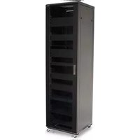
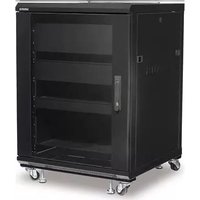
| Product Type | Storage cabinet for audio/video equipment (Component series) |
| Model | CFR2127 (compatible with CFR2100 series) |
| Brand | Sanus |
| Total maximum load capacity | 340.2 kg (750 lb) |
| Load capacity per 2U shelf | 22.6 kg (50 lb) |
| Load capacity per 1U shelf | 13.6 kg (30 lb) |
| Load capacity per 3U shelf (optional) | 36.2 kg (80 lb) |
| Materials | Heavy-duty steel |
| Approximate dimensions (W x H x D) | Approximately 60 x 180 x 90 cm (for a standard 27U rack) |
| Cabinet weight (approximate) | Varies by configuration, approximately 60-80 kg |
| Number of shelves included | 5 x 2U shelves and 2 x 1U shelves (typical configuration) |
| Casters | Yes, with brakes |
| Leveling feet | Included, adjustable |
| Front door | Yes, with glass and handle, reversible |
| Rear panels | Removable for cable management and ventilation |
| Door lock | Optional (sold separately) |
| Ventilation | Ventilated panel and space for optional fan |
| Cable management | Removable rear panels and cable routing paths |
| Shelf ganging | Possible with included ganging brackets |
| Warranty | Standard manufacturer's warranty (refer to manual) |
| Cleaning and maintenance | Wipe with a soft dry or slightly damp cloth. Do not use abrasive products. |
| Recommended operating temperature | Up to 40 °C (104 °F) inside the cabinet |
| Country of origin | China (typical for Sanus) |
Frequently Asked Questions - CFR2127 SANUS
User questions about CFR2127 SANUS
0 question about this device. Answer the ones you know or ask your own.
Ask a new question about this device
Download the instructions for your Storage furniture in PDF format for free! Find your manual CFR2127 - SANUS and take your electronic device back in hand. On this page are published all the documents necessary for the use of your device. CFR2127 by SANUS.
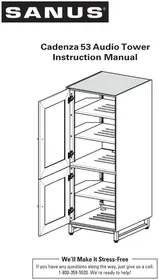
USER MANUAL CFR2127 SANUS
CFR2115, CFR2127, CFR2136, CFR2144
Instruction Manual
We'll Make It Stress-Free
If you have any questions along the way, just give us a call.
1-800-359-5520. We're ready to help!
IMPORTANT SAFETY INSTRUCTIONS – SAVE THESE INSTRUCTIONS PLEASE READ ENTIRE MANUAL PRIOR TO USE
Thank you for choosing a Sanus Component Series Rack. The CFR2100 series is designed to support audio/video equipment.
The total weight capacity for the CFR2100 series:
CFR2115 226.8 kg (500 lb)
CFR2127 340.2 kg (750 lb)
CFR2136 385.5 kg (850 lb)
CFR2144 453.6 kg (1,000 lb)
Each 2U shelf supports up to 22.6 kg (50 lb), and each 1U shelf supports up to 13.6 kg (30 lb).
Each optional 3U shelf supports up to 36.2 kg (80 lb).
CAUTION: Avoid potential personal injuries and property damage!
- Do not exceed the stated weight capacities.
- Do not shake, tilt, rock, sit, stand, or climb on your Component Series Rack. Tipping may cause injury or death.
- Do not move large racks by yourself; due to weight and height, assistance is required.
• To avoid instability do not pull out more than one optional drawer or slide out equipment at a time. - Before moving, make sure all optional drawers and slide out equipment are secured and door is closed and secured.
- Use extreme caution when moving a loaded rack! Push, DO NOT pull, loaded rack slowly over a short, smooth, level distance. Avoid sudden starts and stops to minimize the strain placed on casters.
- Do not use this product for any purpose not explicitly specified by manufacturer.
- If you do not understand these instructions, or have doubts about the safety of the installation, assembly or use of this product, contact manufacturer Customer Service or call a qualified contractor.
• Manufacturer is not responsible for damage or injury caused by incorrect assembly or use.
NOTE: Due to continuous product improvement, images shown in this manual may vary from actual product.
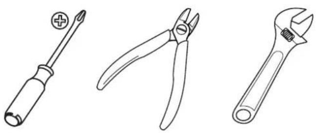
Do you have all of the tools needed?
natural_image
Line drawings of three different tools: screwdriver, pliers, and adjustable wrench (no text or symbols present)Unpacking
Before starting assembly, verify all parts are included and undamaged. If any parts are missing or damaged, do not return the damaged item to your dealer; contact Customer Service. Never use damaged parts!
Supplied parts are located inside of the rack. To access the parts, remove the back panel.
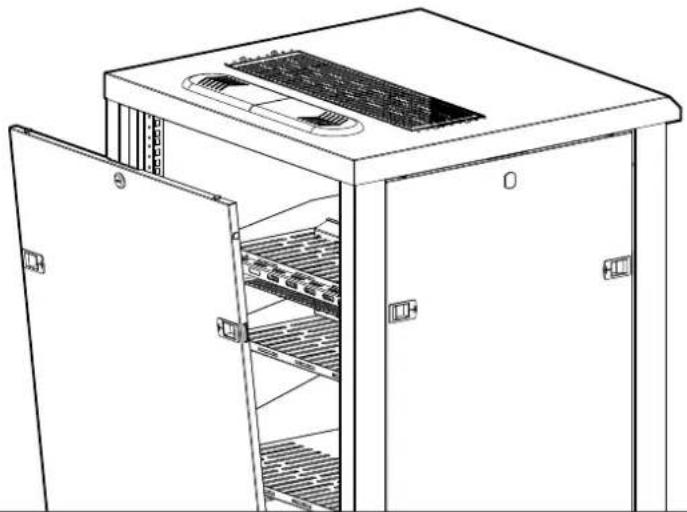
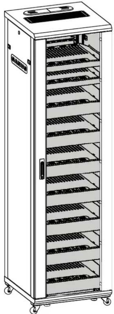
natural_image
Line drawing of a server rack cabinet with open doors and internal shelves (no text or symbols)Parts and Hardware
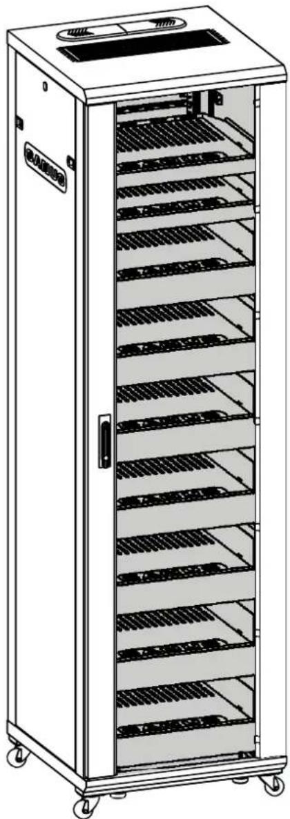
natural_image
Line drawing of a multi-tiered industrial storage cabinet with shelves and top panel (no text or symbols)01x1
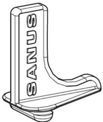
natural_image
Technical line drawing of a mechanical bracket with no visible text or symbols03
CFR2115 8
CFR2127 12
CFR2136 16
CFR2144 18
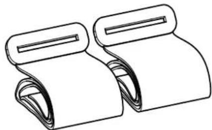
natural_image
Line drawing of two rolled-up paper sheets with scroll handles (no text or symbols)04
CFR2115 4
CFR2127 6
CFR2136 8
CFR2144 9
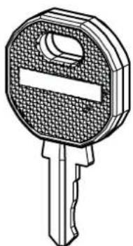
natural_image
Technical line drawing of a key with a handle and spout (no text or symbols)02x2
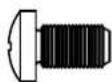
M5 x 10 mm 10-32 x 3/4 in.
05
CFR2115 8
CFR2127 8
CFR2136 8
CFR2144 8
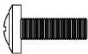
06
CFR2115 4
CFR2127 8
CFR2136 12
CFR2144 16
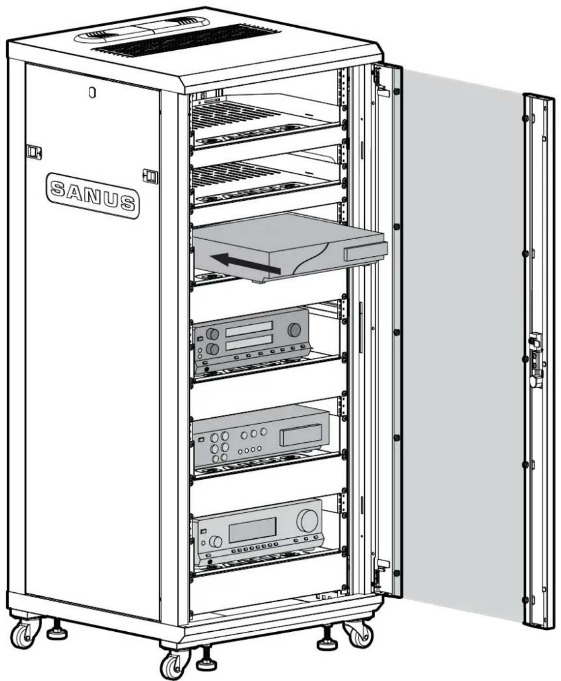
Load Your Components
▲ CAUTION: Failure to follow loading requirements could lead to instability causing personal injury and/or property damage:
To prevent instability:
• Always load the rack from the bottom up and load the heaviest item first.
- 50% of the total weight should be mounted in the lower 1/3 of the rack.
natural_image
Line drawing of a SANUS server rack cabinet with open door, showing internal components and ventilation slots (no text or symbols on main structure)Load Your Components

▲ CAUTION: Failure to follow loading requirements could lead to instability causing personal injury and/or property damage:
To prevent instability:
• Always load the rack from the bottom up and load the heaviest item first.
- 50% of the total weight should be mounted in the lower 1/3 of the rack.
- Follow these additional requirements when loading rack on its back and then lifting rack to an upright position:
- Leveling feet, if installed, need to be adjusted all the way in.
- You must not load more than 20% of the total rated load prior to lifting rack to upright position.
- All equipment should be securely fastened to the rack.
- Use caution when lifting rack to upright position as casters may roll. Assistance is required.
natural_image
Mechanical device diagram showing a wheel and base with an upward arrow indicating motion (no text or symbols)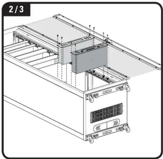
natural_image
Technical line drawing of a server rack unit with mounting hardware and ventilation system (no text or symbols)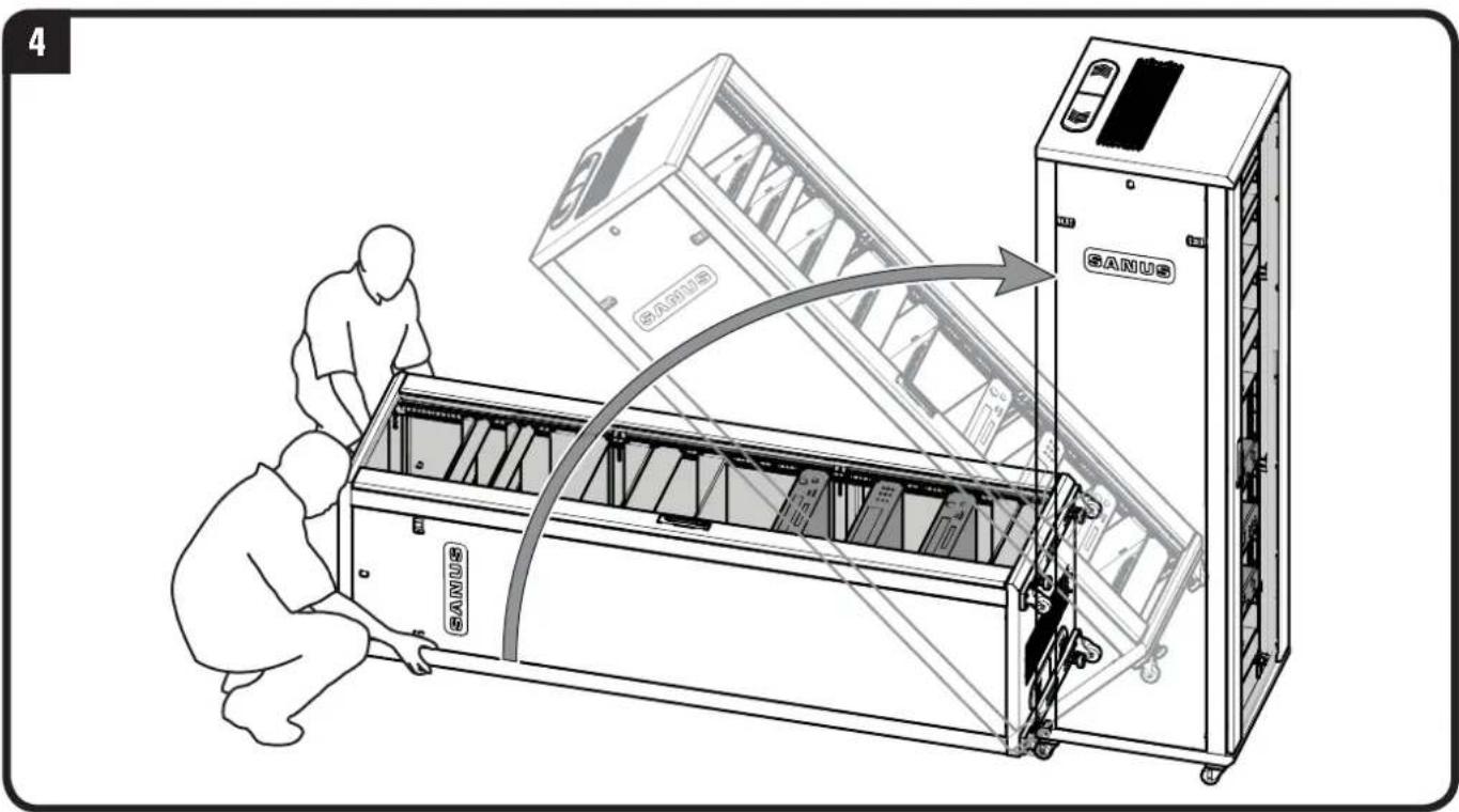
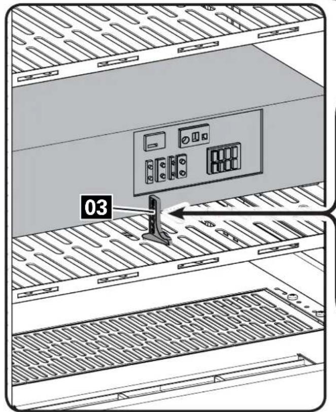
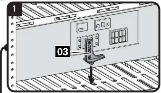
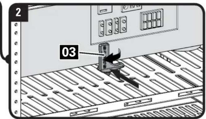
Using Backstops and Component Straps
Rack Shelf Backstops
NOTE: rear view with back panels removed.
- Insert backstop 03 into slot behind component.
- Slide backstop 03 forward until firmly against component and twist 90 degrees.
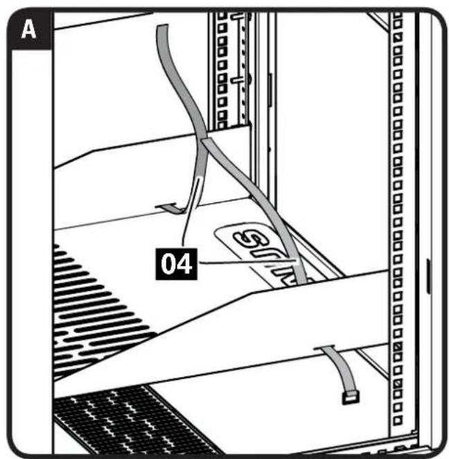
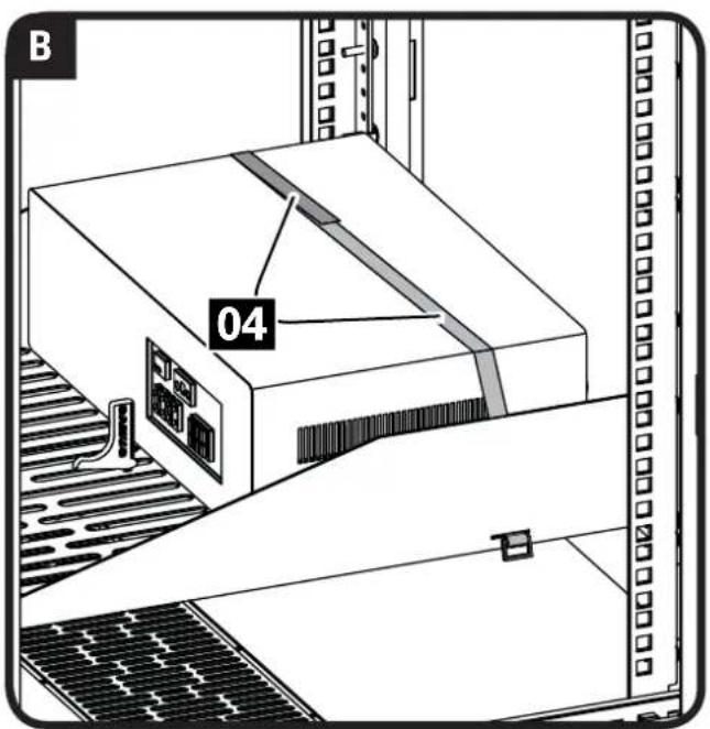
Component Straps
NOTE: side view with panels removed.
A. Slide straps 04 through slots in sides of shelves.
B. Wrap straps 04 over component to secure.

Access Panels for Cable Management

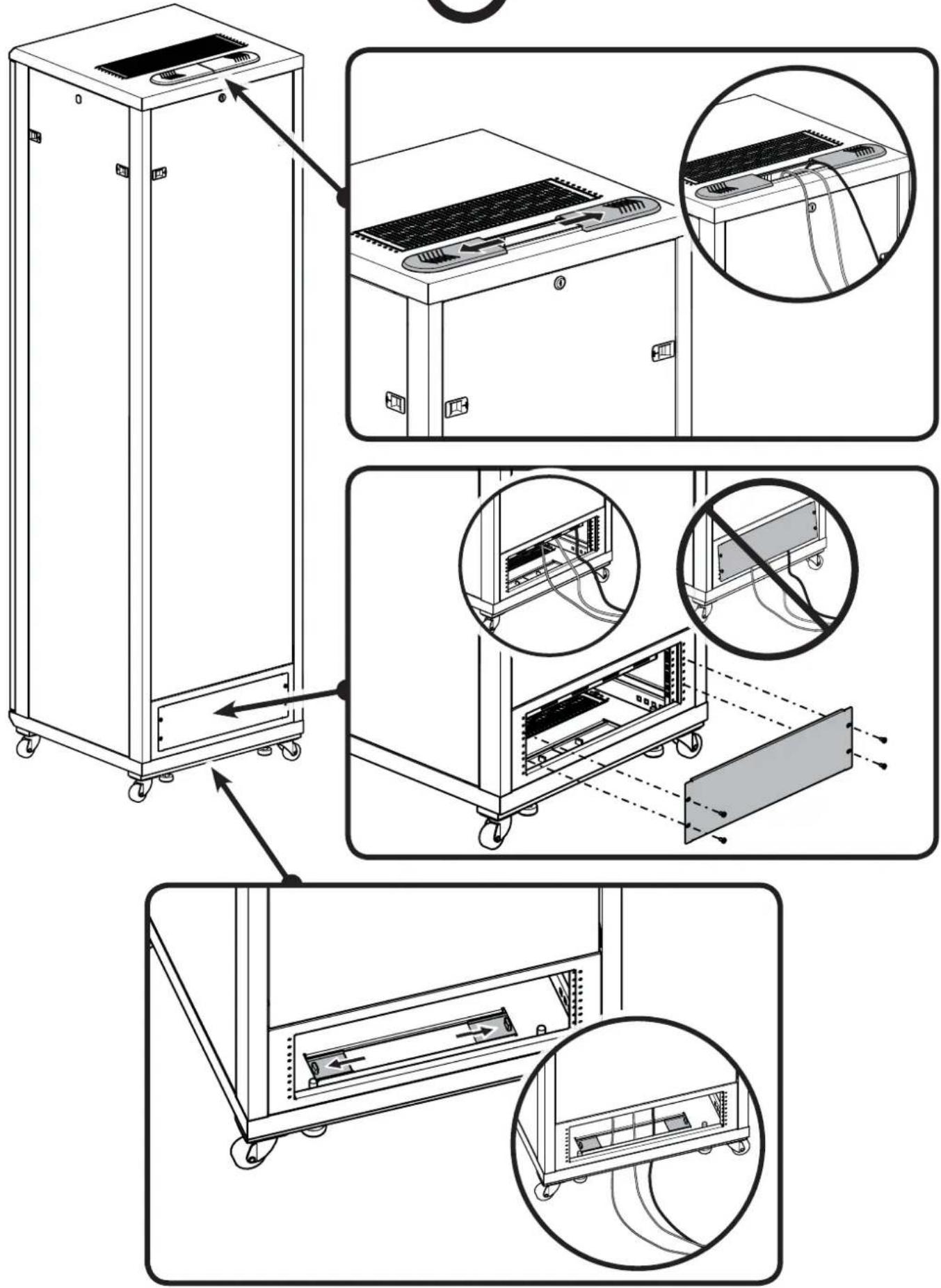
Install Fan for Additional Ventilation (Top or Bottom)
CAUTION: Avoid damage to your components due to overheating. Make sure that there is adequate space between each unit for proper airflow. Operating temperature inside the rack must not exceed 104°F (40°C).
To install fan:
Remove the vented panel. ▲ CAUTION: Cut edges may be sharp.
Remove any metal burrs that remain in the panel frame. Mount the cooling fan using the screws 05 included.
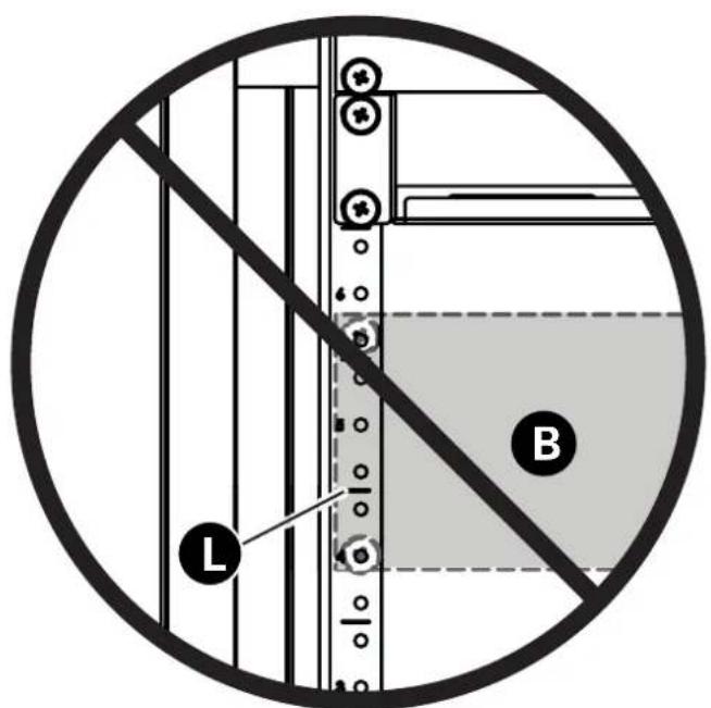
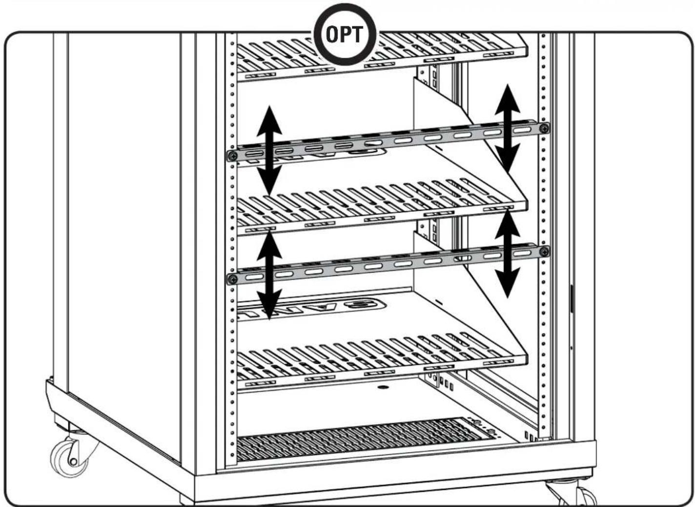
Adjust Shelves and Blanking Panels
NOTE: Align the bottom of the shelf or blanking panel B with the lines L on the rack rail.

natural_image
Line drawing of a multi-tiered stainless steel kitchen cabinet with shelves and wheels (no text or symbols)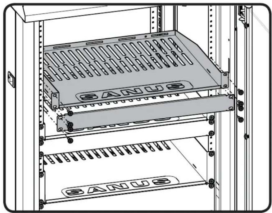
natural_image
Technical line drawing of a server rack with labeled 'SANUS' panels and mounting holes (no text or symbols beyond branding)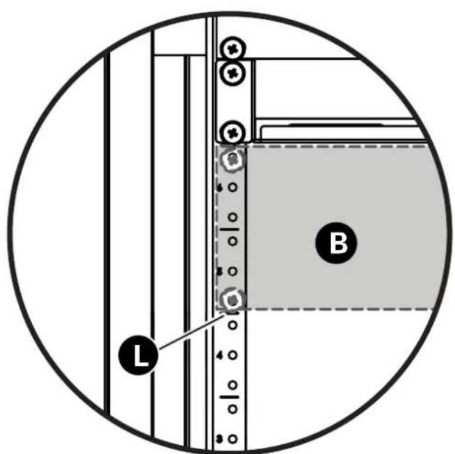
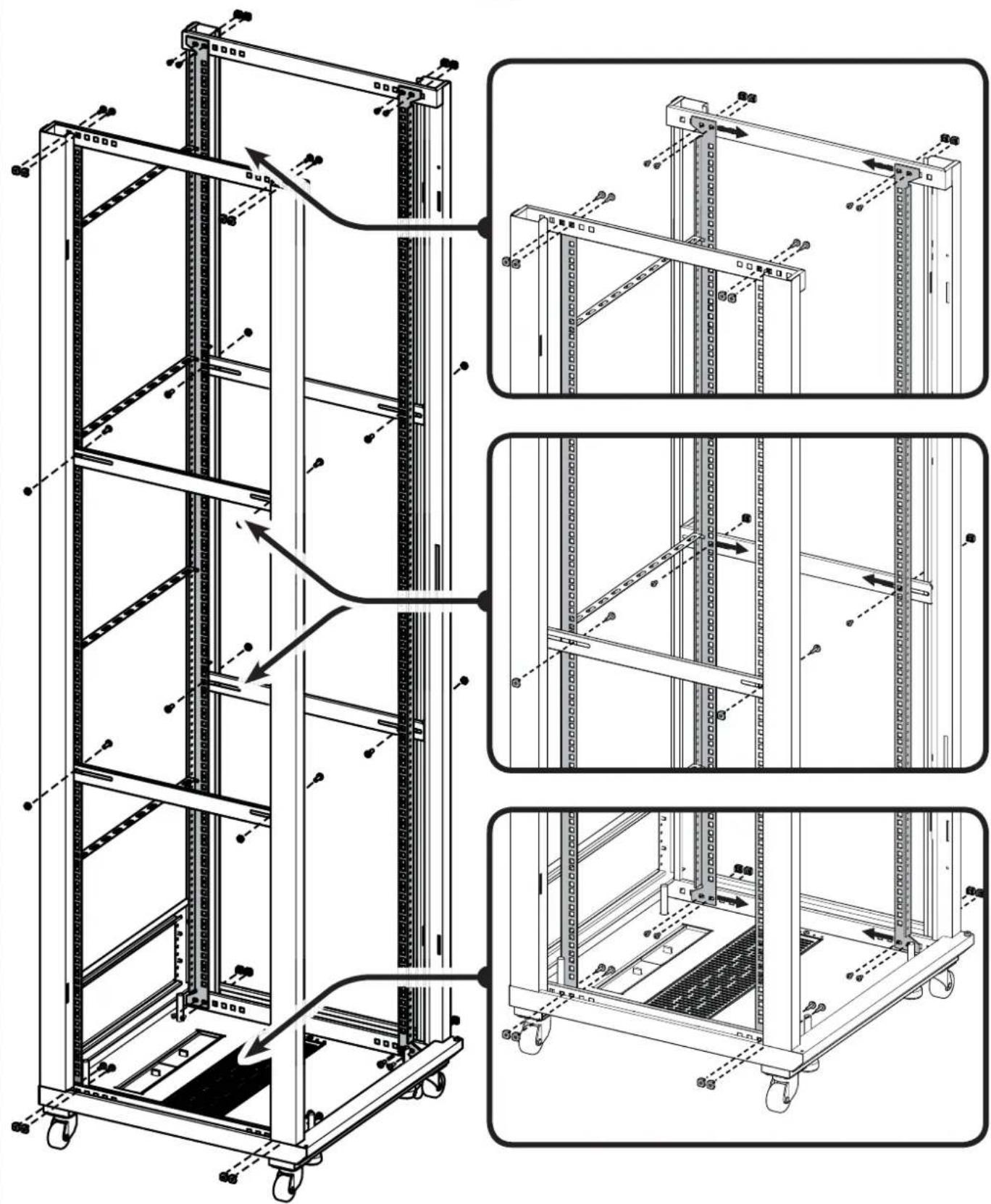
Adjust Rack Rails
Remove the shelves and blanking panels before adjusting the rails. Adjust the right and left rails evenly.
NOTE: For clarity, the front door, top, and side panels are not shown.

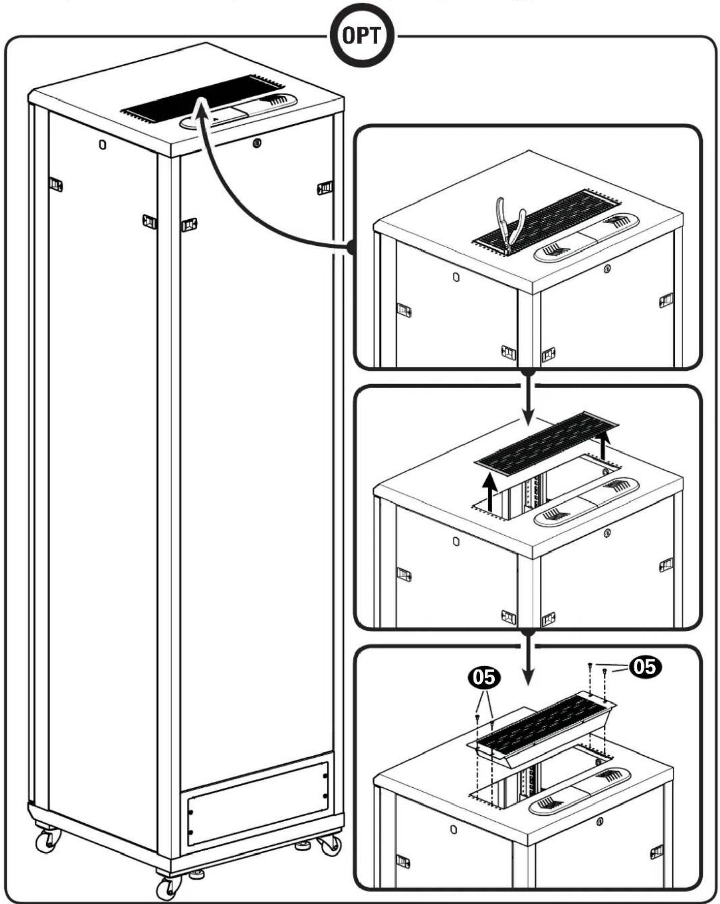
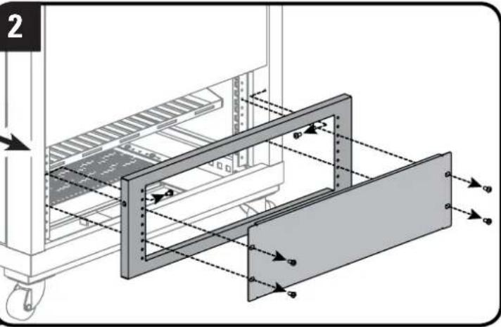
OPT
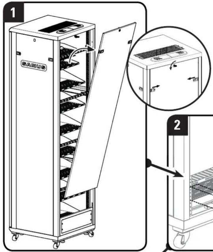
- Remove large upper panel.
- Remove small lower panel and frame.
- Fit bottom of large panel into rack frame and angle the panel up until sliding locks snap in place.
- Flip small panel 180 degrees.
- Screw panel frame into rack frame and replace small panel.
natural_image
Technical diagram of a mechanical assembly with labeled components and directional arrows (no text or symbols present)3
natural_image
Line drawing of a BANUS industrial machine with internal rack structure and open door (no text or symbols)4

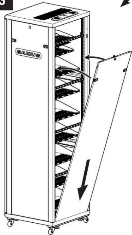
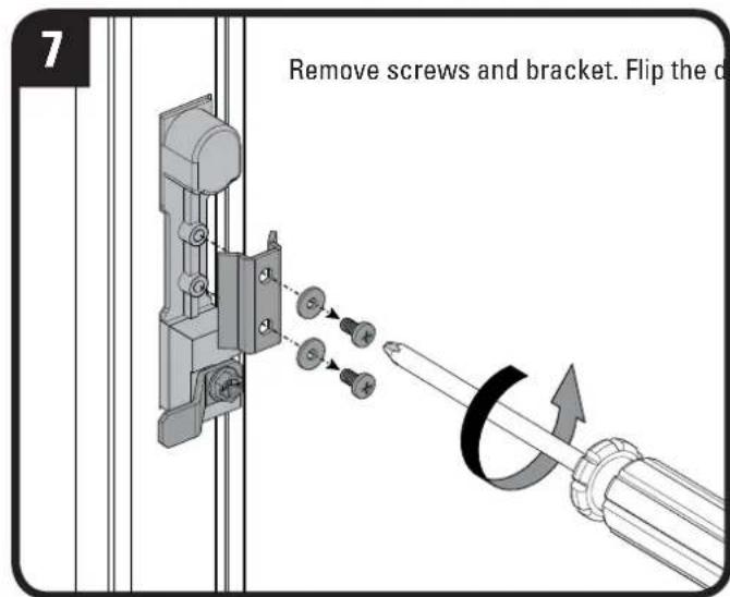
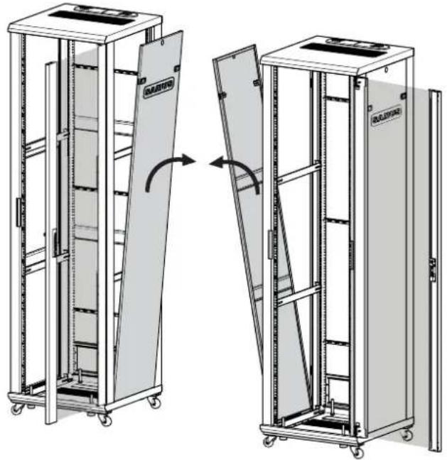
Reverse the Front Door
Remove the door
OPT
- Turn upper door pin to release from locking tab and pull down to release door from rack and lift door from rack frame.
- Release upper pin and turn it back to secure it with the locking tab.
- Remove spacer from bottom door pin.
NOTE: Spacer must be used with pin on bottom of door.
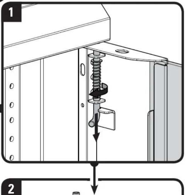
natural_image
Mechanical assembly diagram showing a spring-loaded mechanism with a cylindrical component inserted into a frame (no text or symbols)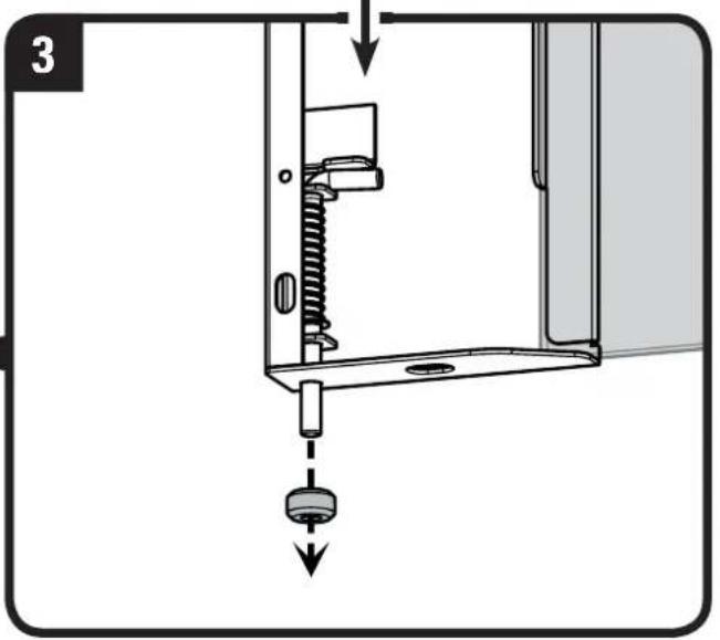
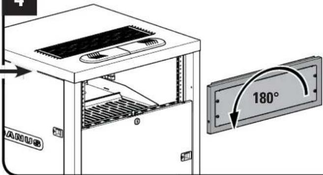
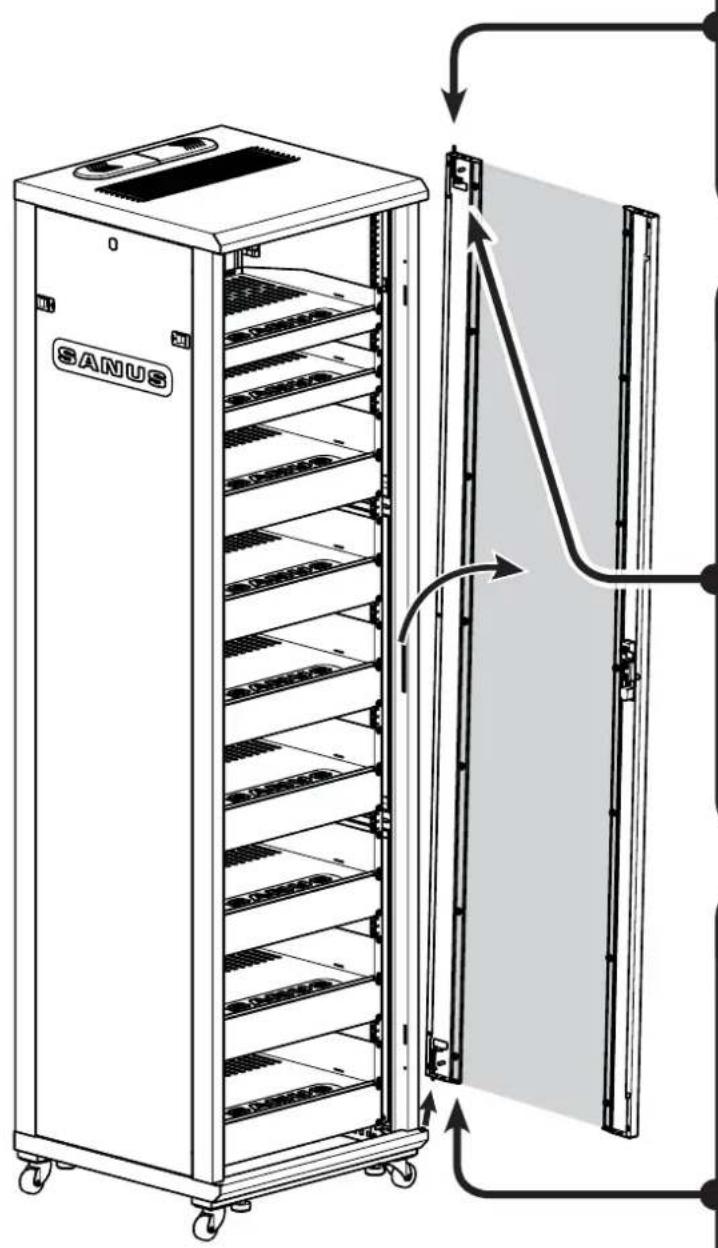
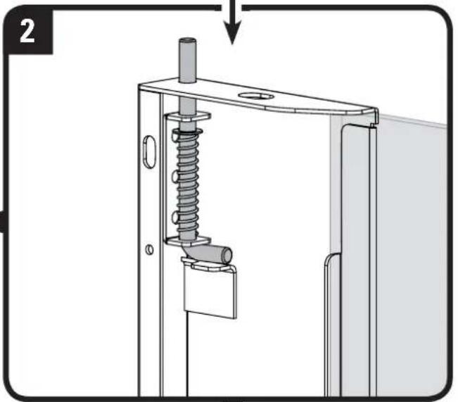
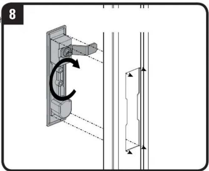
Reverse the Front Door - continued
Flip the door

flowchart
graph TD
    A["6: Mount panel with spring"] --> B["4: Spring assembly with spring"]
    B --> C["5: Spring assembly with spring"]
    C --> D["4: Spring assembly with spring"]
    D --> E["5: Lock assembly with spring"]
    E --> F["6: Lock assembly with spring"]

    subgraph Details
        G["4. Fit spacer onto bottom pin and fit bottom pin into bottom mounting hole in rack"]
        H["5. Turn upper pin to release from locking tab and pull down. Fit pin into upper mounting hole in rack"]
        I["6. Release pin and turn pin to secure it with locking tab"]
    end

    G --> G1["SANUS"]
    H --> H1["SANUS"]
    I --> I1["SANUS"]
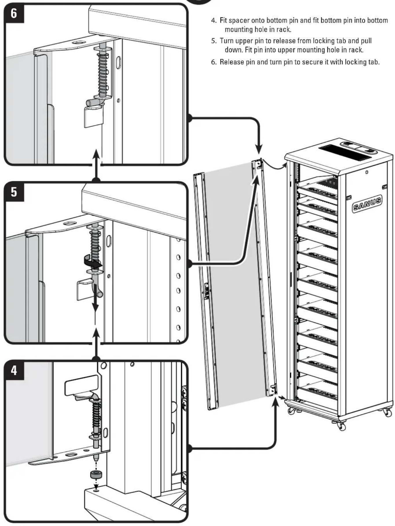
- Fit spacer onto bottom pin and fit bottom pin into bottom mounting hole in rack.
- Turn upper pin to release from locking tab and pull down. Fit pin into upper mounting hole in rack.
- Release pin and turn pin to secure it with locking tab.
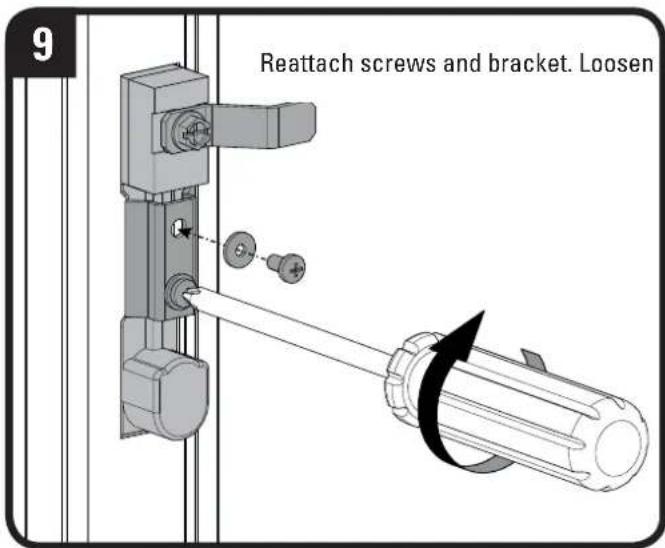
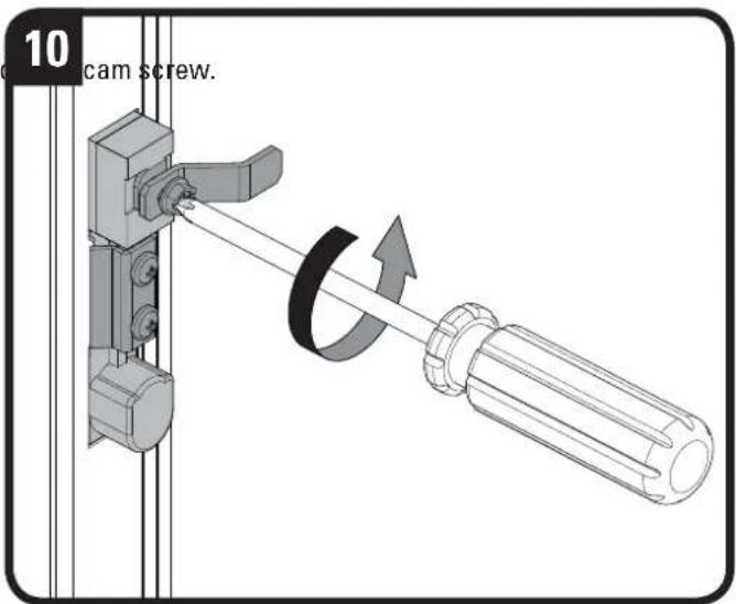
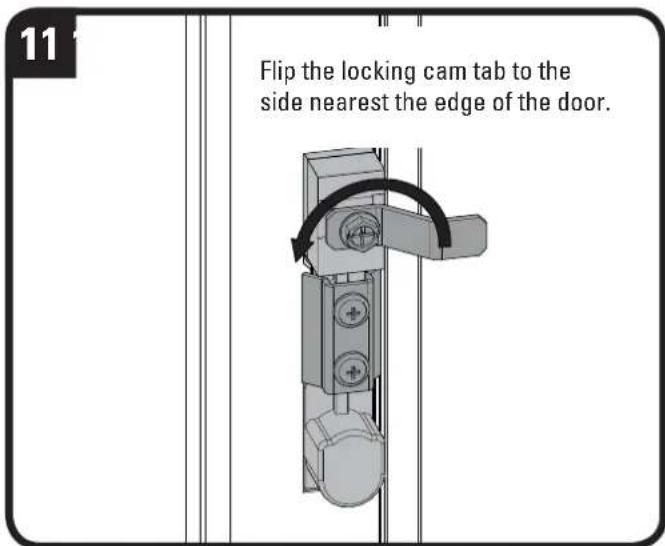
Reverse the Front Door - continued
Flip the door
OPT

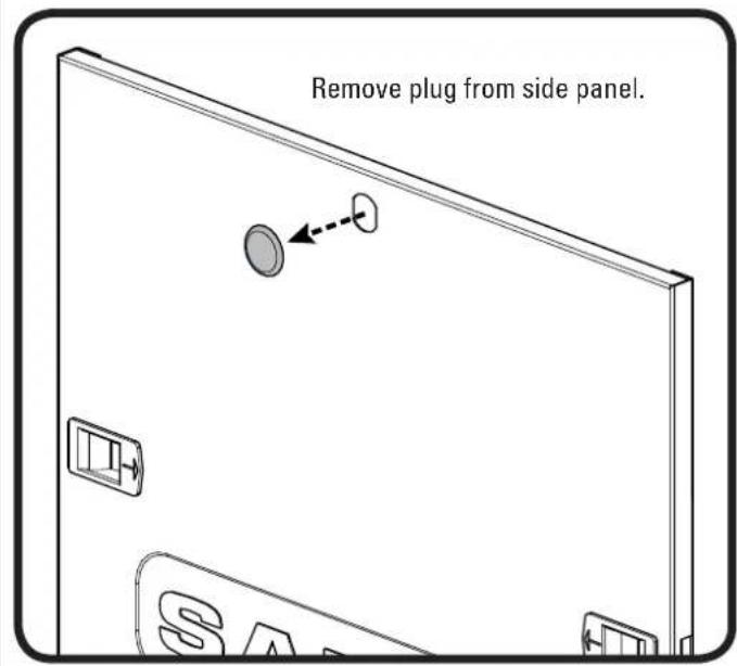
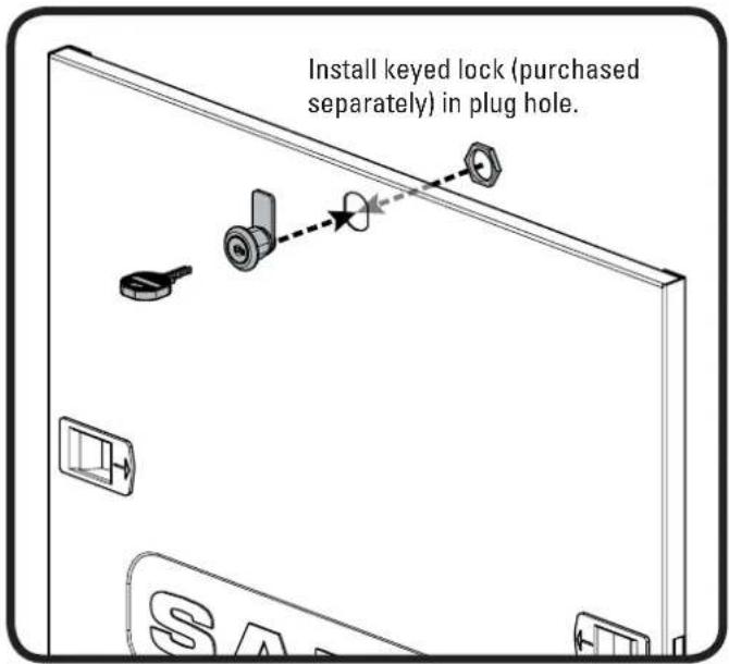
Add Keyed Lock to Door (Sold Separately)
OPT
Manage Cables
OPT
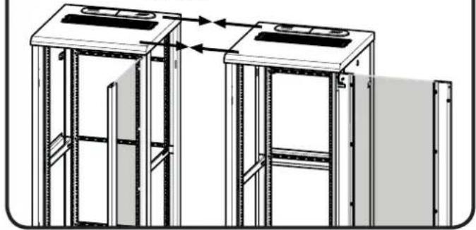
Ganging Racks (Ganging Kit Sold Separately)
OPT
1
Remove side panels on sides to be connected.
natural_image
Technical line drawing of two modular server racks with open doors, showing structural changes (no text or symbols)2
Move racks together until sides are touching.
natural_image
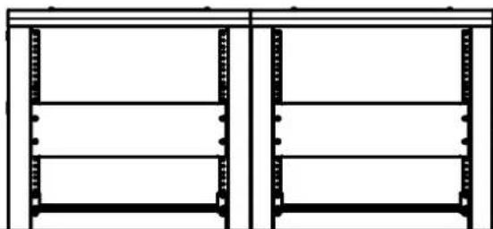
Technical line drawing of two identical mechanical or architectural frame structures with vertical supports and horizontal beams, no text or symbols present.3
IMPORTANT

Make sure both racks are level with each other.
natural_image
Pure architectural line drawing of two identical rectangular metal frame structures without any text, labels, or symbols.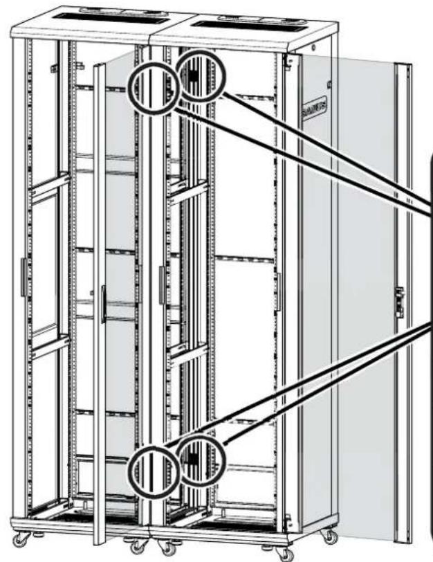
natural_image
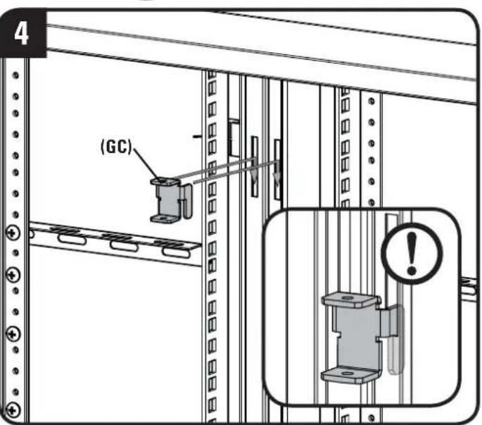
Technical line drawing of a multi-level server rack cabinet with mounting holes and diagonal railings (no text or symbols)Fit four ganging clips (GC) into frame slots. Press down on clips to secure.
IMPORTANT

Make sure all four ganging clips are fully engaged.
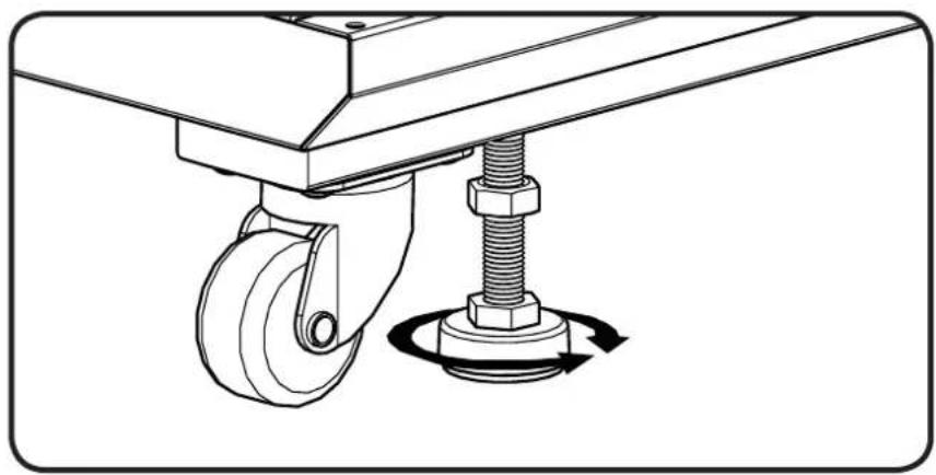
OPT
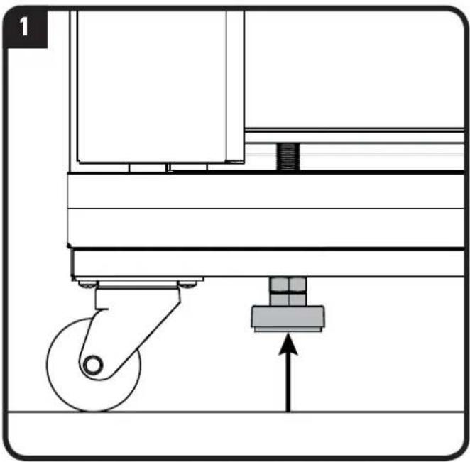
Adjust the feet to level the rack. Tighten nuts until they are flush with the bottom of the rack.
CAUTION: To avoid potential injury or property damage, always ensure that your rack is level.
natural_image
Technical line drawing of a mechanical lift with a spring and bolt, showing rotational motion (no text or symbols)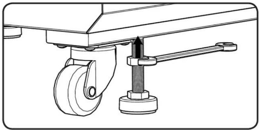
natural_image
Technical line drawing of a mechanical assembly with wheels and a bolted joint (no text or symbols)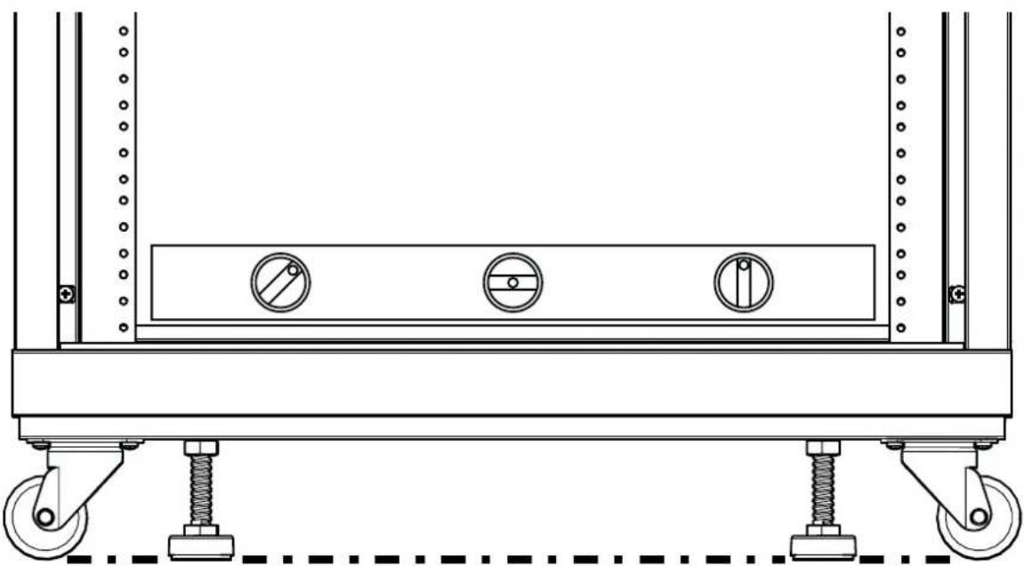
natural_image
Technical line drawing of a mechanical support frame with wheels, springs, and three circular components (no text or symbols)Ajustar as prateleiras e os painéis cegos
ver página 9
Ajustar as calhas do bastidor
ver página 10
Thank you for choosing Sanus! Please take a moment to let us know how we did:

Call us: 1-800-359-5520
UK: 0800 056 2853

Email us: info@sanus.com

Leave a review: sanus.com
Milestone AV Technologies and its affiliated corporations and subsidiaries (collectively, "Milestone"), intend to make this manual accurate and complete. However, Milestone makes no claim that the information contained herein covers all details, conditions, or variations. Nor does it provide for every possible contingency in connection with the installation or use of this product. The information contained in this document is subject to change without notice or obligation of any kind. Milestone makes no representation of warranty, expressed or implied, regarding the information contained herein. Milestone assumes no responsibility for accuracy, completeness or sufficiency of the information contained in this document.
©2014 Milestone AV Technologies. All rights reserved. Sanus is a division of Milestone.
All other brand names or marks are used for identification purposes and are trademarks of their respective owners.