CMS 503ICT PI - Speaker TANNOY - Free user manual and instructions
Find the device manual for free CMS 503ICT PI TANNOY in PDF.


User questions about CMS 503ICT PI TANNOY
0 question about this device. Answer the ones you know or ask your own.
Ask a new question about this device
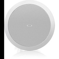
Download the instructions for your Speaker in PDF format for free! Find your manual CMS 503ICT PI - TANNOY and take your electronic device back in hand. On this page are published all the documents necessary for the use of your device. CMS 503ICT PI by TANNOY.
USER MANUAL CMS 503ICT PI TANNOY
natural_image
Close-up of two white ceramic speakers with black centers and mounting holes (no text or symbols visible)CMS 3.0 Series
CMS803DC BM/PI/Q / CMS803 PI BACKCAN
8" Full Range Ceiling Loudspeaker with Dual Concentric Driver
CMS603DC BM/PI / CMS603ICT BM/PI/LS / CMS603 PI BACKCAN
6" Full Range Ceiling Loudspeaker with Dual Concentric or ICT Driver
CMS503DC BM/PI/LP / CMS503ICT BM/PI/LP / CMS503 PI BACKCAN
5" Full Range Ceiling Loudspeaker with Dual Concentric or ICT Driver
CMS403DCE / CMS403ICTE
4" Full Range Ceiling Loudspeaker with Dual Concentric or ICT Driver and adjustable "eyeball" design
2 CMS 3.0 Series Quick Start Guide 3
EN
Safety Instruction
-
Read these instructions.
-
Keep these instructions.
-
Need all warnings.
-
Followal instructions.
-
Do not use this apparatus near water.
-
Clean dry with dry bulb.
-
Do not think any ventilation openings install in accordance with the manufacturer's instructions.
-
In actiatal transversal system
as radiators, heat registers, stores, or other apparatus
(including amplifiers) that produce heat
- Use only attachments/accessories specified
by the manufacturer.
ES

- Use only with
the cart, stand, tripod,
obtects of 1962 specified to the maculatus of
with the sum
DE
When a game is required
PT
combination to assist injury from tis-sex

- Correct disposal of this
product: This symbol indicates that
this product must not be disposed
2020年1月1日
(2019)5III and your national
law. This product should be taken
to a collection center licensed for
the recycling of waste electrical and electronic equipment (EEE). The mishandling of this type of waste could have a possible negative impact on the environment and human health due to potentially hazardous substances that are generally associated with EEE. At the same time, your cooperation in the correct disposal of this product will contribute to the efficient use of natural resources. For more information about where you can take your waste equipment for recycling, please contact your local city office, or your household waste collection service.
- Do not install in a confined space, such as a
book case or similar unit.
- Do not place naked flame sources, such as lighted
candles, on the apparatus.
prelimous, a 3 pieces
rencommandis parle
a liquidation process is necessary. A small container is made using a control unit for the use of the material.
des débets
in recycling fuel, other and electric power (EE)
-
What is the best of the
-
Mac fanial e lightes o minutes, his own
-
Die alschatrischen aktivamente
aresas, schm. apuriba.
support, personnel, state
provements n vasculati com
The Ground Truth image displays a single, solid horizontal line. According to Rule 2 (UNDERSCORE & LINE RULES), this is a stylistic or background line, not a placeholder underscore. Therefore, the OCR result must ignore it and output nothing or only meaningful text. The provided OCR content is "____", which consists of four underscores. This is an incorrect interpretation of the line as a placeholder, violating the rule that stylistic lines must be ignored. The OCR has hallucinated underscores where none should exist based on the GT's visual context. Hence, the OCR result is inconsistent with the Ground Truth.
PT
IT
4 CVS 3.0 Series Quick Start Guide 5
HL Belangrijke
houseprice 3.04 mag upgrades 2) product market
Thank you for purchasing this Tannoy Ceiling Monitor System product. Designed for both speech and music program material, the Tannoy CMS range provides exceptional sonic quality and long-term reliability in all ceiling mount applications. The CNS 3.0 DC series features new 16 ohm Dual Concentric drivers for improved performance and prolonged service life.
Unpacking
Every Tannoy product is carefully inspected before shipment. After unpacking, please inspect your product to ensure no damage has occurred in transit. In the unlikely event of damage, please notify your dealer and retain all shipping materials as your dealer may require return shipment.
All CMS loudspeakers are shipped in pairs and provided with the following accessories as standard: C-ring, tile-bridge kit, cut-out template and paint mask. A plaster (mud) ring is available as an optional accessory.
Safety Notices
Some regional construction codes require the use of a secondary method of securing loudspeakers in the ceiling to provide security of a backup support. A secondary support line should be attached from the safety loop on the rear of the product to a source point on the ceiling. For PI models, the secondary support line should be attached from the back of the driver chassis to a source point on the ceiling. Please consult the relevant construction codes in your region.
When using a power driver to install the product, it is essential to use the correct torque level settings to avoid over-tightening and damage to the ceiling material or clamps. Recommended torque setting: 1.5 Nm
Tannoy will not be held responsible for any damages caused by the improper installation of these loudspeakers.
The CMS 603 ICT LS is UL-1480, category UUMW, for use with non-DC supervised systems.
Electrical Safety Notice: To comply with the standard IL-1480, metal-clad flexible conduit (5K) is required for connection to the terminal block for proper earth grounding.
In order to comply with UL regulations, the PI backcan must always be used with the CMS PI models.
SHE
In addition, the following is a 100% 1980. It is required to be used in the first section of the actual call processing unit and the subsequent instructions are being applied to the other with the necessary procedure for handling the process. The procedure is not possible that
Product Feature Identification
IMPORTANT NOTE: Drawings for each loudspeaker below are generic and apply to the loudspeaker types specified. Some variations will be apparent in some models, but differences are not critical for installation purposes except as noted.
Blind Mount
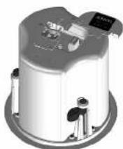
The blind-mount models are supplied with a pre-fitted backcan. Above applies to all models as well any others that do NOT have a "PI" suffix.
Pre-install
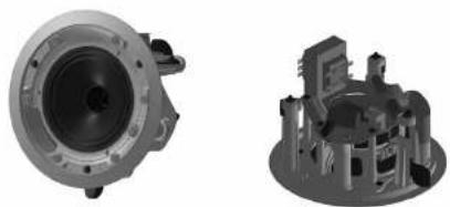
natural_image
Two technical illustrations of mechanical components, one showing a circular housing and the other a 3D architectural model (no text or symbols visible)A pre-install (PI) unit is shown without the optional pre-install backcan.
Pre-install backcan
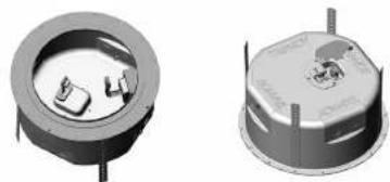
natural_image
Two 3D mechanical components with internal cavities and mounting holes, shown from different angles (no text or symbols visible)Optional pre-install (PI) backcan for PI models.
NOTE: The CMS 603DC / ICT PI and CMS 803DC models have the transformer pre-attached to the inside of the backcan. The CMS 503DC / ICT PI has the transformer pre-attached to the loudspeaker assembly.
8 CVS 3.0 Series Quick Start Cuke 9
Accessories
Standard Accessories
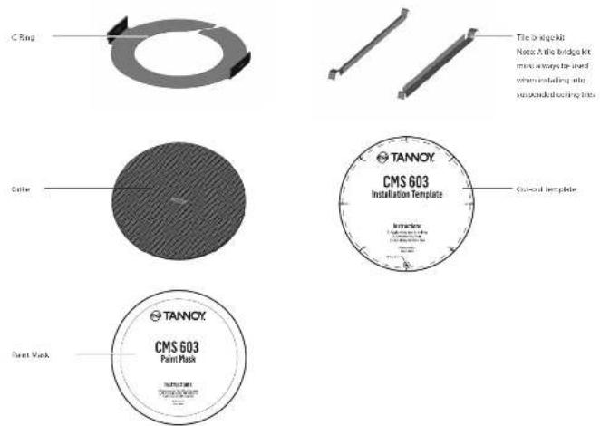
text_image
C Ring Tile bridge hib Note: A file bridge kit must always be used when installing site separated cooling tiers Color TANNOX CMS 603 Installation Template Cut-out template Paint Mask TANNOX CMS 603 Paint MaskOptional Accessories

Installation Guide for Suspended Ceilings
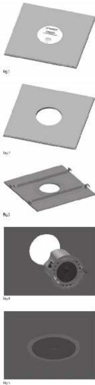
- Remove the ceiling tile from its frame and place it on a flat surface. Position the cutout template (self adhesive backed) on the tile. (Fig.1)
- Cut out the hole in the ceiling tie using a pad saw following the broken line indicated on the template (Fig.2)
- Place the C-Ring and tile-bridge on top of the ceiling panel, aligning the C-Ring over the hole, and screw the C-Ring to the tile bridge using the fixings provided. (Fig. 3)
-
Go to the 'Wiring and Setting Up' chapter.
-
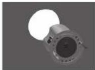
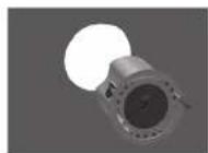
Slide the speaker assembly through the hole. Turn the screws (denoted "Screw Fox") clockwise on the front of the speaker to extend the mounting wings. Tighten the screws until a firm grip is achieved. (NOTE: Screws have a Poziziv head; use of a Poziziv driver is recommended). If using a power driver, Tannoy recommends a torque setting of 1.3 Km. (Fig.4) DO NOT OVERTIGHTEN!
-
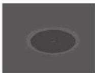
Attach the nylon safety to the hooks on the front taffle before attaching the gille by presenting it to the speakers and allowing the magnets to pull it into position (Fig.5). (With the CMS 403DCelCTe, the gille is already fitted to the product.)
NOTE ON INSTALLATION OF CMS 403DCe/ICTe:
Before tightening the screws in step 5, swivel the speaker in the desired direction. When the screws are tightened, the speaker will lock into position. Replace the front trim to conceal the mounting screws.
10 CMS 3.0 Series
Installation Guide for Sheetrock (Plasterboard) Ceilings
- Position the cutout template (self adhesive backed) on the ceiling. (Fig.1)
- Cut out the hole in the ceiling using a pad saw following the broken line indicated on the template then slide the C-ring into the ceiling, aligning it over the cut-out hole. (Fig.2)
- Go to the 'Wiring and Setting Up' chapter, then return to point 4 below.
- Slide the speaker assembly through the holo. Turn the screws (denoted "Screw Fix") clockwise on the front of the speaker to extend the mounting wings. Tighten the screws until a form grip is achieved. [NOTE: Screws have a PazDriv head; use of a PazDriv driver is recommended]. If using a power driver, Tannoy recommends a torque setting of 1.5 Nm. (Fig.3) DO NOT OVERTIGHTEN!
- Attach the nylon safety to the hooks on the front table before attaching the grille by presenting it to the speakers and allowing the magnets to pull it into position (Fig.4). (With the CVS-403DCe/ICTe, the grille is already fitted to the product.)
NOTE ON INSTALLATION OF CMS 403DCe/ICTe:
Before tightening the screws in step-1, stivel the speaker in the desired direction. When the screws are tightened, the speaker will lock into position. Replace the front trim to conceal the mounting screws.

Fig.1

[5]
19.1
184
Installation Guide for Optional Plaster Ring
Quick Star Guide 11
EN
An optional plaster (mud) ring bracket is available from Tannoy. This bracket is designed to be pre-installed into newly constructed, non-suspended ceilings.
-
Nail or screw the plaster ring to the joints. (Fig. 1)
-
Lay the speaker wiring to where the speaker will be fitted and complete the plastering work on the ceiling. (Fig.2)
-
Go to the 'Wiring and Setting Up' chapter, then return to point 4 below.
-
Slide the speaker assembly through the hole. Turn the screws (denoted "Screw Fox") clockwise on the front of the speaker to extend the mounting wings. Tighten the screws until a firm grip is achieved. (Note: Screws have a PoziDriv head; use of a PoziDriv driver is recommended). If using a power driver, Tamney recommends a torque setting of 1.5 Km. (Fig.3)
DO NOT OVERTIGHTEN!
- Attach the nylon safety to the hooks on the front baffle before attaching the grille by presenting it to the speakers and allowing the magnets to pull it into position (Fig.4). With the CMS 4030Co/CTe, the grille is already fitted to the product.)

Hg

Fig.2
B(3
FLL4
NOTE ON INSTALLATION OF CMS 403DCE/ICTe:
Before tightening the screws in step 4, swivel the speaker in the desired direction. When the screws are tightened, the speaker will lock into position. Replace the front trim to conceal the mounting screws.
12 CVS 3.0 Series Quick Start Juice 13
Installation Guide for Optional Pre-Installation Backcan (PI Models Only)
An optional pre-install backcan is available for all pre-install [PI] models. The backcan is designed for pre-installation in newly constructed, non-suspended ceilings. NOTE: The CMS 603DC/CT and CMS BHDX models have the transformer pre-attached to the inside of the backcan; the CMS 503DC/CT models have the transformer pre-attached to the loudspeaker assembly.
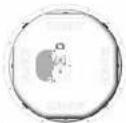
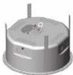
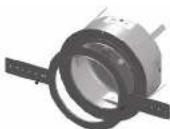
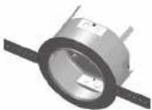
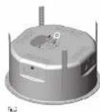
- Attach the backcan to a safe and secure fixing point. This can be done in a number of ways. METHOD 1: Fix the backcan to a secure fixing point by using suitable fixings with the 4 fixing holes provided on the PI backcan. (Fig.1)
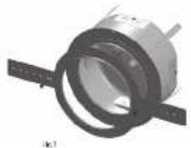
METHOD 2: Secure the backcan to a safe and secure fixing point using suitable fixings with the flexible straps that are attached to the P1 backcan. (Fig.2)
METHOD 3:
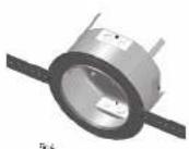
a. Attach the PI backcan to the optional pre-mount ring (plaster ring) using the fixings provided with the pre-mount ring. (Fig.3)
b. Next, secure the wings of the pre-mount ring to a safe and secure fixing point by using suitable fixings. (Fig.4)
Please turn over
1
F42
131
F44
Installation Guide for Optional Pre-Installation Backcan (PI Models Only)
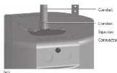
- Attach the conduit to the installed backcan. This can be done in two ways:
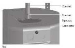
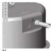
METHOD 1: You can use the clamp at the back of the pre-install backcan. The product will accept a squeeze connector with a thread size of up to 22 mm. To remove the cable clamp, simply uncrew the threaded washer (under the wiring cover) which holds the cable clamp in place and replace it with a conduit squeeze connector. (Fig.5)
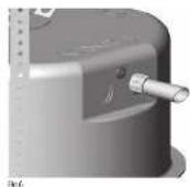
METHOD 2: You can use any of the three knock-out points at the sides of the PI backcan (19 mm, 22 mm or 28 mm diameter). (Fig.6)
-
If conduit is not chosen as the wiring method, run an approved speaker cable to the installed can. Terminate in the top mounted cable clamp or with an approved cable connector in one of the three knock-out points at the sides of the PI backcar.
-
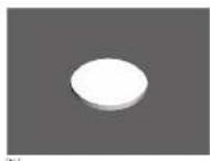
Cut hole in the proper location in the ceiling using a pad saw. Place the pre-install backcan over the hole. (Fig.7)
-
Go to the 'Wiring and Setting Up' chapter, then return to point 6 below.
-
Side the speaker assembly through the note. Turn the screws (denoted "Screw Fix") clockwise on the front of the speaker to extend the mounting wings. Tighten the screws until a form grip is achieved. NOTE: Screws have a PostDrive head; use of a PostDrive driver is recommended). If using a power driver, Tammy recommends a torque setting of 1.5 Nm. (Fig. 8) DO NOT OVERTIGHTEN!
-
Attach the nylon safety to the hooks on the front baffle before attaching the grille by presenting it to the speakers and allowing the magnets to pull it into position. (Fig.9)
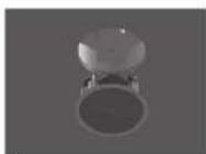
增
Fig.5
Wiring and Setting Up
-
Open the wiring cover (if applicable) and locate the Euro-type connector plug and socket at the back of the speaker. [Fig.1]
-
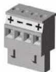
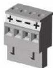
For connection to an amplifier, use Pins 1 and 2 (Fig.2):
• Fin 1 is positive
- Pin 2 is negative
For connection to additional speakers in a distributed line, Pins 3 and 4 are in parallel where: • Pin 3 is negative
- Pin 4 is positive
-
Close the wiring cover and tighten both screws on the cable clamp (if applicable).
-
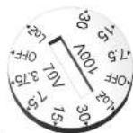
Use the rotary switch on the front of the unit to select low impedance (Lo2) mode or high impedance (70 V or 100 V) for distributed applications.
THE SPEAKER IS SUPPLIED IN LOW IMPEDANCE MODE. NEVER CONNECT THE SPEAKER TO A 70/100 VOLT AMPLIFIER WHILE IT IS SET FOR LOW IMPEDANCE.
CMS 403DC/e/ICTe and CMS 503DC/ICT models (all variants) use a 30 W transformer. In distributed line applications, the transformer can be tapped at 30 W, 15 W and 7.5 W, with an additional 3.75 W tap for 70 V line systems. [Fig.3]
CMS 603DC/CT and CMS 803DC models (all variants) use a 60 W transformer. In distributed line applications, the transformer can be tapped at 60 W, 30 W and 15 W, with an additional 7.5 W tap for 70 V line systems. (Fig.4)
Quick Star Guide
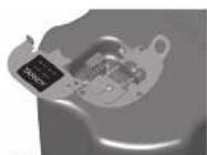
Fig.1
1027
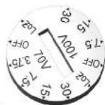
(b).
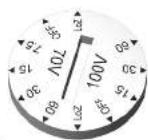
Fig.1
Painting
If desired, the grille and baffle panel may be painted to match the surrounding décor.
Painting the baffle:
- Carefully mask off the driver assembly using the paint mask provided to ensure that the paint does not come into contact with the cone and roll surround.
- Apply several thin coats of paint – this will provide a better finish than one overly thick coat.
Painting the grille:
- Carefully remove the acoustically transparent grille cloth from the reverse side of the grille.
- Paint the grille and then replace the grille cloth - several thin coats of paint will provide a better finish than one overly thick coat.
- Re-bond the grille cloth to the grille over the entire area using a light spray-adhesive to avoid audible resonances.
Introducción
text_image
The bridge kit Note: A bit bridge kit must always be used when mounting into supervised ceiling tiles TANNOY CMS 603 Installation Template Cut-out temperature20 CMS 3.0 Series
Quick Start Guide 21
- 2017年
In terms of the cost of the cost of the cost of the cost of the cost of the cost of the cost of the cost of the cost of the cost of the cost of the cost of the cost of the cost of the cost of the cost of the cost of the cost of the cost of the cost of the cost of the cost of the cost of the cost of the cost of the cost of the cost of the cost of the cost of the cost of the cost of the cost of the cost of the cost
• 1 x broken out positive
natural_image
3D rendering of a cylindrical mechanical component with mounting holes and a small labeled component (no visible text or symbols)text_image
The bridge kit Note: As the bridge kit must always be used when needing into supervised scaling tiles TANNOY CMS 603 Installation Template Cust-to-encenceOptionales Zubehör
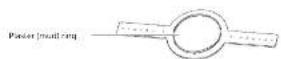
In the case of the first, we are not a particular case in the case 5.0003. The case is not a particular case in the case 1.0004. This case is not a particular case in the case 2.0005. The case is not a particular case in the case 3.0006.
Pré-instalar backcan
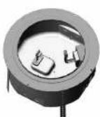
natural_image
3D rendering of a cylindrical industrial device with mounting flanges and a central hub (no visible text or symbols)text_image
TFile bridge kit Note: A file bridge kit must always be used when mounting into supervised ceiling tiles TANNOY CMS 603 Installation Template Laser-enclear Laser-enclearFor the best work, the best job created in 1980, the best job created in 1981, the best job created in 1982, the best job created in 1983, the best job created in 1984, the best job created in 1985, the best job created in 1986, the best job created in 1987, the best job created in 1988, the best job created in 1989, the best job created in 1990, the best job created in 1991, the best job created in 1992, the best job created in 1993, the best job created in 1994, the best job created in 1995, the best job created in 1996, the best job created in 1997, the best job created in 1998, the best job created in 1999, the best job created in 2000, the best job created in 2001, the best job created in 2002, the best job created in 2003, the best job created in 2004, the best job created in 2005, the best job created in 2006, the best job created in 2007, the best job created in 2008, the best job created in 2009, the best job created in 2010, the best job created in 2011, the best job created in 2012, the best job created in 2013, the best job created in 2014, the best job created in 2015, the best job created in 2016, the best job created in 2017, the best job created in 2018, the best job created in 2019, the best job created in 2020, the best job created in 2021, the best job created in 2022, the best job created in 2023, the best job created in 2024, the best job created in 2025, the best job created in 2026, the best job created in 2027, the best job created in 2028, the best job created in 2029, the best job created in 2030, the best job created in 2031, the best job created in 2032, the best job created in 2033, the best job created in 2034, the best job created in 2035, the best job created in 2036, the best job created in 2037, the best job created in 2038, the best job created in 2039, the best job created in 2040, the best job created in 2041, the best job created in 2042, the best job created in 2043, the best job created in 2044, the best job created in 2045, the best job created in 2046, the best job created in 2047, the best job created in 2048, the best job created in 2049, the best job created in 2050, the best job created in 2051, the best job created in 2052, the best job created in 2053, the best job created in 2054, the best job created in 2055, the best job created in 2056, the best job created in 2057, the best job created in 2058, the best job created in 2059, the best job created in 2060, the best job created in 2061, the best job created in 2062, the best job created in 2063, the best job created in 2064, the best job created in 2065, the best job created in 2066, the best job created in 2067, the best job created in 2068, the best job created in 2069, the best job created in 2070, the best job created in 2071, the best job created in 2072, the best job created in 2073, the best job created in 2074, the best job created in 2075, the best job created in 2076, the best job created in 2077, the best job created in 2078, the best job created in 2079, the best job created in 2080, the best job created in 2081, the best job created in 2082, the best job created in 2083, the best job created in 2084, and
From the following table, we also need to be a 15.3300.1986 billion USD of U.S. dollar reserves and are subject to which it is a 4.271 million dollars, and you should be a 1.400 billion USD or more. The results of the \1 billion share of the \1 billion shares are subject to this report. In our future years, we will continue to maintain the value of \$1 billion in 2007, however, we will continue to have a higher level of capitalization and leverage that would have been held for the next year through 2008. We still expect to have a longer time period than the next year.
natural_image
3D rendering of a cylindrical mechanical component with mounting holes and a small labeled component (no visible text or symbols)text_image
TFile bridge kit Note: A file bridge kit must always be used when using into supervised ceiling tiles TANNOY CMS 603 Installation Template Laser-enclear Insererize: 1. Insererize the system is not insererized by the system is not insererize the system is not insererize the system is notValfria Tillbehör

Thank you for purchasing this Tannoy Ceiling Monitor System product. Designed for both speech and music program material, the Tannoy CMS range provides exceptional sonic quality and long-term reliability in all ceiling mount applications. The CMS 3.0 DC series features new 16 ohm Dual Concentric drivers for improved performance and prolonged service life.
Unpacking
Every Tannoy product is carefully inspected before shipment. After unpacking, please inspect your product to ensure no damage has occurred in transit. In the unlikely event of damage, please notify your dealer and retain all shipping materials as your dealer may require return shipment.
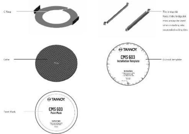
All CMS loudspeakers are shipped in pairs and provided with the following accessories as standard: C-ring, tile-bridge kit, cut-out template and paint mask. A plaster (mud) ring is available as an optional accessory.
Safety Notices
Some regional construction codes require the use of a secondary method of securing loudspeakers in the ceiling to provide security of a backup support. A secondary support line should be attached from the safety loop on the rear of the product to a source point on the ceiling. For PI models, the secondary support line should be attached from the back of the driver chassis to a source point on the ceiling. Please consult the relevant construction codes in your region.
When using a power driver to install the product, it is essential to use the correct torque level settings to avoid over-tightening and damage to the ceiling material or clamps. Recommended torque setting: 1.5 Nm
Tannoy will not be held responsible for any damages caused by the improper installation of these loudspeakers.
The CMS 603 ICT LS is UL-1480, category UUMW, for use with non-DC supervised systems.
Electrical Safety Notice: To comply with the standard IL-1480, metal-clad flexible conduit (BK) is required for connection to the terminal block for proper earth grounding.
In order to comply with UL regulations, the PI backcan must always be used with the CMS PI models.
[Unreadable]
In addition, the number of numbers in the number of numbers is 1.25308 (1983). It corresponds to the number of numbers in the number of numbers in the number of numbers in the number of numbers in the number of numbers in the number of numbers in the number of numbers in the number of numbers in the number of numbers in the number of numbers in the number of numbers in the number of numbers in the number of numbers in the number of numbers in the number of numbers in the number of numbers in the number of numbers in the number of numbers in the number of numbers in the number of numbers in the number of numbers
Product Feature Identification
IMPORTANT NOTE: Drawings for each loudspeaker below are generic and apply to the loudspeaker types specified. Some variations will be apparent in some models, but differences are not critical for installation purposes except as noted.
Blind Mount
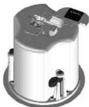
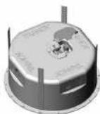
The blind-mount models are supplied with a pre-fitted backcan. Above applies to all models as well any others that do NOT have a "PI" suffix.
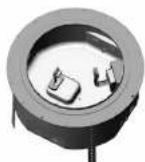
Pre-install
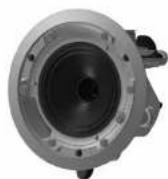
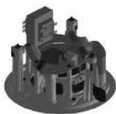
A pre-install [PI] unit is shown without the optional pre-install backcan.
Pre-install backcan
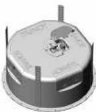
Optional pre-install (PI) backcan for PI models.
NOTE: The CMS 603DC / ICT PI and CMS 803DC models have the transformer pre-attached to the inside of the backcan. The CMS 503DC / ICT PI has the transformer pre-attached to the loudspeaker assembly.
96 CMS3.0 Series
Accessories
Standard Accessories
text_image
C Ring Color Paint Mask Tile bridge hib None & the bridge kit must always be used when installing site separated cooling tiles TANNOY CMS 603 Installation Template Cut-out template TANNOY CMS 603 Paint MaskOptional Accessories

Quick Star Guide
Installation Guide for Suspended Ceilings
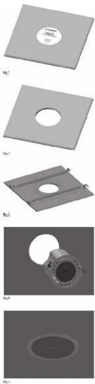
- Remove the ceiling tile from its frame and place it on a flat surface. Position the cutout template (self adhesive backed) on the tile. (Fig.1)
- Cut out the hole in the ceiling tie using a pad saw following the broken line indicated on the template (Fig.2)
- Place the C-Ring and tile-bridge on top of the ceiling panel, aligning the C-Ring over the hole, and screw the C-Ring to the tile bridge using the fixings provided. (Fig. 3)
-
Go to the 'Wiring and Setting Up' chapter.
-
Slide the speaker assembly through the hole. Turn the screws (denoted "Screw Fox") clockwise on the front of the speaker to extend the mounting wings. Tighten the screws until a firm grip is achieved. (NOTE: Screws have a Poziziv head; use of a Poziziv driver is recommended). If using a power driver, Tannoy recommends a torque setting of 1.3 Km. (Fig.4) DO NOT OVERTIGHTEN!
-
Attach the nylon safety to the hooks on the front taffle before attaching the gille by presenting it to the speakers and allowing the magnets to pull it into position (Fig.5). (With the CMS 403DCelCTe, the gille is already fitted to the product.)
NOTE ON INSTALLATION OF CMS 403DCe/ICTe:
Before tightening the screws in step 5, swivel the speaker in the desired direction. When the screws are tightened, the speaker will lock into position. Replace the front trim to conceal the mounting screws.
98 CMS3.0 Series
Quick Steel Guide 99
Installation Guide for Sheetrock (Plasterboard) Ceilings
- Position the cutout template (self adhesive backed) on the ceiling. (Fig.1)
- Cut out the hole in the ceiling using a pad saw following the broken line indicated on the template then slide the C-fang into the ceiling, aligning it over the cut-out hole. (Fig.2)
- Go to the 'Wiring and Setting Up' chapter, then return to point 4 below.
- Slide the speaker assembly through the holo. Turn the screws (denoted "Screw Fix") clockwise on the front of the speaker to extend the mounting wings. Tighten the screws until a form grip is achieved. [NOTE: Screws have a PazDriv head; use of a PazDriv driver is recommended]. If using a power driver, Tannoy recommends a torque setting of 1.5 Nm. (Fig.3) DO NOT OVERTIGHTEN!
- Attach the nylon safety to the hooks on the front table before attaching the grille by presenting it to the speakers and allowing the magnets to pull it into position (Fig.4). (With the CMS-403DCe/ICTe, the grille is already fitted to the product.)

Fig.1

[5]
19.1
184
NOTE ON INSTALLATION OF CMS 403DCe/ICTe:
Before tightening the screws in step 4, trigger the speaker in the desired direction. When the screws are tightened, the speaker will lock into position. Replace the front trim to conceal the mounting screws.
Installation Guide for Optional Plaster Ring
An optional plaster (mud) ring bracket is available from Tannoy. This bracket is designed to be pre-installed into newly constructed, non-suspended ceilings.
- Nail or screw the plaster ring to the joints. (Fig. 1)
- Lay the speaker wiring to where the speaker will be fitted and complete the plastering work on the ceiling. (Fig.2)
- Go to the 'Wiring and Setting Up' chapter, then return to point 4 below.
- Slide the speaker assembly through the hole. Turn the screws (denoted "Screw Fox") clockwise on the front of the speaker to extend the mounting wings. Tighten the screws until a firm grip is achieved. (Note: Screws have a PoziDriv head; use of a PoziDriv driver is recommended). If using a power driver, Tamney recommends a torque setting of 1.5 Km. (Fig.3)
DO NOT OVERTIGHTEN! - Attach the nylon safety to the hooks on the front baffle before attaching the grille by presenting it to the speakers and allowing the magnets to pull it into position (Fig.4). With the CMS 4030Ce/CTe, the grille is already fitted to the product.)

Hg

Fig.2
B(3
FLL4
NOTE ON INSTALLATION OF CMS 403Dc/ICTe:
Before tightening the screws in step 4, swivel the speaker in the desired direction. When the screws are tightened, the speaker will lock into position. Replace the front trim to conceal the mounting screws.
100 CMS 3.0 Series Quick Start Guide 101
Installation Guide for Optional Pre-Installation Backcan (PI Models Only)
An optional pre-install backcan is available for all pre-install [P] models. The backcan is designed for pre-installation in newly constructed, non-suspended ceilings. NOTE: The CMS 603DC/ICT and CMS BDIDC models have the transformer pre-attached to the inside of the backcan; the CMS 503DC/ICT models have the transformer pre-attached to the loudspeaker assembly.
- Attach the backcan to a safe and secure fixing point. This can be done in a number of ways: METHOD 1: Fix the backcan to a secure fixing point by using suitable fixings with the 4 fixing holes provided on the PI backcan. (Fig.1)
METHOD 2: Secure the backcan to a safe and secure fixing point using suitable fixings with the flexible straps that are attached to the PI backcan. (Fig.2)
METHOD 3: a. Attach the PI backcan to the optional pre-mount ring (plaster ring) using the fixings provided with the pre-mount ring. (Fig.3)
b. Next, secure the wings of the pre-mount ring to a safe and secure fixing point by using suitable fixings. (Fig. 4)
Please turn over

Installation Guide for Optional Pre-Installation Backcan (PI Models Only)
- Attach the conduit to the installed backcan. This can be done in two ways:
METHOD 1: You can use the clamp at the back of the pre-install backcan. The product will accept a squeeze connector with a thread size of up to 22 mm. To remove the cable clamp, simply uncrew the threaded washer (under the wiring cover) which holds the cable clamp in place and replace it with a conduit squeeze connector. (Fig.5)
METHOD 2: You can use any of the three knock-out points at the sides of the PI backcan (19 mm, 22 mm or 28 mm diameter). (Fig.6)
-
If conduit is not chosen as the wiring method, run an approved speaker cable to the installed can. Terminate in the top mounted cable clamp or with an approved cable connector in one of the three knock-out points at the sides of the PI backcar.
-
Cut hole in the proper location in the ceiling using a pad saw. Place the pre-install backcan over the hole. (Fig.7)
102 CMS 3.0 Series Quick Start Guide 103
-
Go to the 'Wiring and Setting Up' chapter, then return to point 6 below.
-
Side the speaker assembly through the hole. Turn the screws (denoted "Screw Fix") clockwise on the front of the speaker to extend the mounting wings. Tighten the screws until a form grip is achieved. NOTE: Screws have a PostDrive head; use of a PostDrive driver is recommended). If using a power driver, Tammy recommends a torque setting of 1.5 Nm. (Fig.8) DO NOT OVERTIGHTEN!
-
Attach the nylon safety to the hooks on the front baffle before attaching the grille by presenting it to the speakers and allowing the magnets to pull it into position. (Fig.9)
18月
Fig.5
Wiring and Setting Up
-
Open the wiring cover (if applicable) and locate the Euro-type connector plug and socket at the back of the speaker. [Fig.1]
-
For connection to an amplifier, use Pins 1 and 2 (Fig.2);
• Pin 1 is positive
- Pin 2 is negative
For connection to additional speakers in a distributed line, Pins 3 and 4 are in parallel where:
- Pin 3 is negative
- Pin 4 is positive
-
Close the wiring cover and tighten both screws on the cable clamp (if applicable).
-
Use the rotary switch on the front of the unit to select low impedance (Lo2) mode or high impedance (70 V or 100 V) for distributed applications.
THE SPEAKER IS SUPPLIED IN LOW IMPEDANCE MODE. NEVER CONNECT THE SPEAKER TO A 70/100 VOLT AMPLIFIER WHILE IT IS SET FOR LOW IMPEDANCE.
CMS 403DC/e/ICTe and CMS 503DC/ICT models (all variants) use a 30 W transformer. In distributed line applications, the transformer can be tapped at 30 W, 15 W and 7.5 W, with an additional 3.75 W tap for 70 V line systems. [Fig.3]
CMS 603DC/CT and CMS 803DC models (all variants) use a 60 W transformer. In distributed line applications, the transformer can be tapped at 60 W, 30 W and 15 W, with an additional 7.5 W tap for 70 V line systems. (Fig.4)
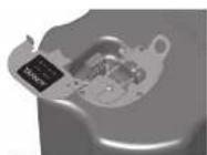
Fig.1
140.7
[1]
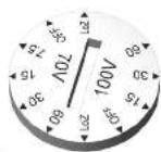
Fig.1
104 CMS 3.0 Series Quick Start Guide 105
Painting
If desired, the grille and baffle panel may be painted to match the surrounding decor.
Painting the baffle:
- Carefully mask off the driver assembly using the paint mask provided to ensure that the paint does not come into contact with the cone and roll surround.
- Apply several thin coats of paint – this will provide a better finish than one overly thick coat.
Painting the grille: - Carefully remove the acoustically transparent grille cloth from the reverse side of the grille.
- Paint the grille and then replace the grille cloth - several thin coats of paint will provide a better finish than one overly thick coat.
- Re bond the grille cloth to the grille over the entire area using a light spray adhesive to avoid audible resonances.
CMS Series Model Dimensions
CMS 803DC BM
Hole Cut-out Size: 295 mm
Tamaño de corte del orificio: 295 mm
Tame de la decoupe du trout. 295 mm
Tamanho do recorte do furc: 295 mm
Dimensione del ritaglio del foro: 295 mm
Gat uitgesreden grootte: 295 mm
Hallskurein Stoffes, 295 mm
Promisswuppungstehres
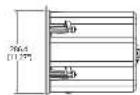
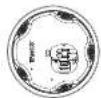
CMS 803DC PI
Hole Cut-out Size: 295 mm
Tamaño de corte del orificio: 295 mm
Taille de la découpe du trou: 295 mm
Lochausschnitt Große: 295 mm
Tamaño do recorte do loro: 295 mm
Diministelle der Risiko betallo, 253 mm
Hörskuran strode: 785 mm
Rozmier wycięcia w otworze: 295 mm
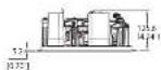
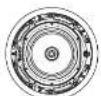
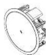
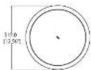


106 CMS 3.0 Series Quick Start Guide 107
CMS Series Model Dimensions
CMS 803DC PI BACKCAN
Hole Cut-out Size: 295 mm
Hole Cut-out Size: 295 mm
CMS Series Model Dimensions
CMS 603DC BM
Hole Cut-out Size: 253 mm
Cat witnesses grade 253,000
Hälsskuren stadek: 253 mm
Hole Cut-out Size: 253 mm
CMS Series Model Dimensions
CMS 603DC PI
Hole Cut-out Size: 253 mm
Tamaño de corte del orificio: 253 mm
Taille de la découpe du trou: 253 mm
Lochausschnit Große: 253 mm
Tamanho do recorte do fundo: 253 mm
Dimensione de maglio de 100.25 mm
Est. de la aplica di 753 mm
Häskurup sterisk: 253 mm
Roomar wyciccia w otworze: 253 mm
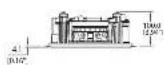


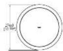
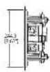
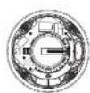
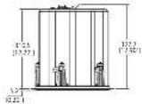
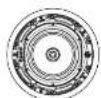
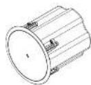
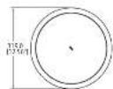
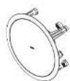
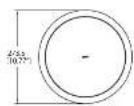
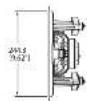
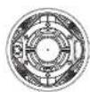
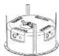
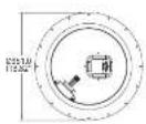
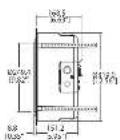
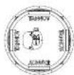
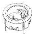
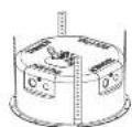
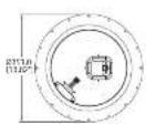
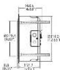
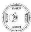
CMS 603ICT PI
Hole Cut-out Size: 253 mm
Tamaño de corte del onificio: 253 mm
Taille de la découpe du trou: 253 mm
Lochausschnitt Größe: 253 mm
Tamanho do recorte do furo: 253 mm
Dimensione del ntaglio del foro: 253 mm
Galt ausgeschieden größte: 253 mm
natskolen 107ek. 253 mm
Bonnier uvisiada wefuero: 151 mm
normal by 1970, 4: 05/12.233 mm
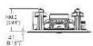
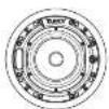
CMS Series Model Dimensions
CMS 603DC PI BACKCAN
Hole Cut-out Size: 253 mm
Tamaño de corte del orificio: 253 mm
Taille de la découpe du trou: 253 mm
Lochausschnitt Große: 253 mm
Tamaño do recorte do rufo: 253 mm
Einheitsteile der Risikurierung. 213 mm
Gesamtengaden geobt. 267 mm
Hörschung stade: 253 mm
Rozmiar wydęcia w otworze: 253 mm

CMS 603ICT PI BACKLAN
Hole Cut-out Size: 253 mm
Tamaño de corte del orificio: 253 mm
Taille de la découpe du trou: 253 mm
Lochausschiff: Größe: 253 mm
tamanho do recorte do dire. 235 mm
Dimensione del Tragno del foro: 253 mm
Hilsskuran stodeir: 253 mm
Rozmier wycięcia w otworze: 253 mm
110 CMS 3.2 Series Quikx San Guade 111
CMS Series Model Dimensions
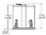
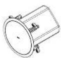
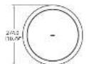
CMS 603ICT LS
Hole Cut-out Size: 253 mm
Tamaño de corte del orificio: 253 mm
Taille de la découpe du trou: 253 mm
Lochausschnit Größe: 253 mm
Tamanho do recorte do fundo: 253 mm
Dimensione de maglio de 100.25 mm
Est. de la aplica di 753 mm
Häskurup sterisk: 253 mm
Roomar wycięcia w otworze: 253 mm

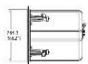

CMS Series Model Dimensions
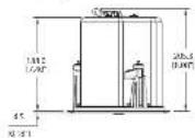
CMS 503DC BM
Hole Cut-out Size: 190 mm
Tamaño de corte del orificio: 190 mm
Taille de la découpe du trou: 190 mm
Lochaußschnitt Große: 190 mm
Trembe der sonstige durch 100 mm
Dimensione del rispetto del forso: 100 mm
Catuitessgaden grootte: 150 mm
Hälsskuren stadek: 190 mm
Rozmiar wycięcia w otworze: 190 mm

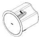
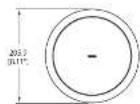
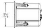

CMS 503ICT BM
Hole Cut-out Size: 190 mm
Tamaño de corte del orificio: 190 mm
Taille de la découpe du trou: 190 mm
Lochausschnitt Grolle: 190 mm
Tamaínho do recorte do ano: 190 mm
Dimensierte der Risiko betallo, 150 mm
Gehaltzernaden mehr, 100 mm
Höckuran strode: 700 mm
Rozmier wycięcia w otworac: 190 mm
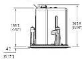

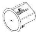
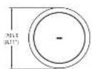
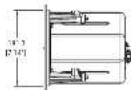

112 CMS 3.2 Series Quicks Scan Guide 113
CMS Series Model Dimensions
CMS 503DC LP
Hole Cut-out Size: 253 mm
Tamaño de corte del orificio: 253 mm
Taille de la découpe du trou: 253 mm
Lochauschnitt Große: 253 mm
Tamarino do recorte do turo: 253 mm
Dimensione de maglio de 100.25 mm
Est. de la aplica di 753 mm
Häskurup sterisk: 253 mm
Roomar wyciccia w otworze: 253 mm
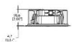
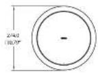

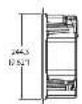
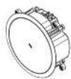

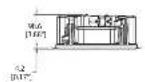
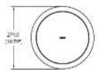
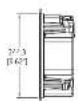
CMS 503ICT LI
Hole Cut-out Size: 253 mm
Tamaño de corte del orificio: 253 mm
laite de la detoupe du trou: 253 mm
Lachalusschnitt Grosse: 253 mm
caminato di teorite di min: 255 mm
Dimensione del italie del fuve: 263 mm
Gesitzermoden operte: 161 mm
Hälsskumpsterlek: 251 mm
Rozmiar wyciecia w otworze: 253 mm



CMS Series Model Dimensions
CMS 503DC FI
Hole Cut-out Size: 190 mm
Tamaño de corte del orificio: 190 mm
Taille de la découpe du trou: 190 mm
Lochausschnitt Große: 190 mm
Tamaño do recorte do rufo: 190 mm
Linnelsliche der Risiken dericht. 150 mm
Geswitzmoden geöht: 100 mm
Hölschungen stade: 100 mm
Rozmiar wycięcia w otworze: 190 mm
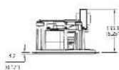
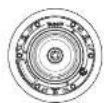
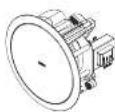
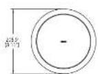
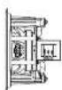

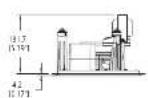
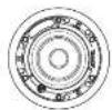
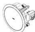
CMS 503ICT PI
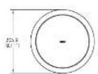
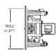
Hole Cut-out Size: 190 mm
Tamaño de corte del orificio: 190 mm
Taille de la découpe du trou: 19
Lochaußschnitt Größe: 190 mm
Tamaño do recorte do ruró: 150 mm
Dimensión del astrolión (lafres: 160 mm
Dimensielle der Risiko der 100 mm
Gat vittverschern oder 150 mm
Hörschuss gradein 200 mm
Rozmiar wydzieja w otworze: 190 mm

114 CMS 3.2 Series Quicks Scan Guide 115
CMS Series Model Dimensions
CMS 503DC PI BACKCAN
Hole Cut-out Size: 190 mm
Hole Cut-out Size: 190 mm
CMS Series Model Dimensions
CMS 403DCe
Hole Cut-out Size: 187 mm
Cat witnesses grade 157,000
Hälsskuren stadek: 187 mm
Hole Cut-out Size: 187 mm
Technical Specifications
| CMS 8030C/Model CMS 8030CQ/Model | ||
| Performance | ||
| Frequency response (3 dB) * | 47 Hz 10 MHz/10 kHz | 47 Hz 30 kHz |
| Frequency range (10 dB) * | 40 Hz 35 MHz/10 kHz | |
| Frequency range (10 dB) * | 41 Hz 35 MHz/10 kHz | |
| System sensitivity (W or Tm) * | 50 dB (1 W = -4 for 16 GHz), 95 dB (1 W = -4 V/m) * Oned | |
| Nominal Coverage Angle underground central 3D degree nominal | ||
| Power Handling* | ||
| Average 50 W | ||
| Programme 180 W | ||
| Peak 300 W | ||
| Recommended Amplifier Power 160/2 g / 16 Ohms | ||
| Nominal Impedance (Co, Z) / 16 Ohms | ||
| Rated minimum SPI | ||
| Average | 112 dB | 113 dB |
| Peak | 110 dB | 119 dB |
| With DIF60-Average | 110 dB | 111 dB |
| Transformer Caps (in front output switch) | ||
| 70V | (4) W (83 c) / 120 W (165 c) / 15 W (230 c) / 25 W (660 c) / 0.85 & low impedance operation, Refer to Note 4. | |
| 100 V | (6) W (165 c) / 200 V (300 c) / 15 V (660 c) / 0.85 & low impedance operation Refer to Note 4. | |
| Transducers | ||
| Dual Concentric point source driver | 1 x 250 mm (20"). dual Concentric driver using Drammagnet technology | |
| Low Frequency | 4 mm (25") color and, colored and blue paper put zone | |
| High Frequency | 25 mm (1.30") PCI zone | |
| Physical | ||
| Endurance | ||
| Backion | Zone colors used | |
| Backie | Redox loaded 10,947-4 rated 645 | |
| Grid | Stairs, with whether connected to charging | |
| Safety Features | Soldering location zone of endzone on the load bearing safety band | |
| Camping Design | Secure by single clock Min / Mass clamping range 9.5 mm (10.35") / 45 mm (12.35") Recommended during torque: 1.5 Min | |
| Backion Options | ||
| Brd Mount (80') | Complete with fixed backion | — |
| Preload (%) | Separated backion for pre installation | — |
| Cable Entry Options | Cube clamp & sequence connection for conduct up to 22 mm | |
| Conduit Breakouts on PI Backion | 3 sets of horizontal position 15 x 22 x 28 mm (10.75" x 0.87" x 1.01) | |
| Connectors | Removable locking connector with transthermal wire with Trap-through facility | |
| Compliance | III, 1400, II, 2043, CT | |
CMS 803DC Models CMS 803DCQ Model
| Physical | ||
| Dimensions | ||
| Board Diameter | 316.0 mm (12.56") | |
| Front of ceiling to rear of backseat | — | 472.5 mm (12.22") |
| Front of ceiling to top of safety loop | — | 322.7 mm (12.90") |
| EM Mount Front of ceiling to rear of backseat | 112.5 mm (12.37") | — |
| EM Mount Front of ceiling to top of safety loop | 322.7 mm (12.90") | — |
| FL Modules: Front of ceiling surface to rear of speaker and | 125.6 mm (8.34") | — |
| FL Module: Front of accessory heater at rear of top of safety loop | 166.5 mm (6.66") | — |
| Hole cutout diameter (all models) | 295 mm (11.60") | |
| Net Weight (gal) | — | 8.5 kg (18.24 lb.) |
| CNS-80000 FL | 8.5 kg (18.34 lb.) | — |
| CNS-80000 FL | 5.0 kg (11.02 lb.) | — |
| FL Jakarta | 4.2 kg (9.25 lb.) | — |
| Included Accessories | G-Box, the-edge box, paint mask, cut-out template, grille | |
| Optional Accessories | Flower (musting, Ace-gnls) | |
| Focked Quantity | 2 | |
Trav
1. 2017年1月1日,公司与关联方达成《关于变更部分募集资金用途的议案》。
2.1.3.4.5.6.7.8.9.10.11.12.13.14.15.16.17.18.19.20.21.
S. Inghaw, 2016, 4: 28:31
A. 2018年,公司与关联方、董事、监事、高级管理人员不存在关联关系。
V. Bung, al., 2016, and 2017, 2018, 2019, 2020, 2021, 2022, 2023, 2024, 2025, 2026, 2027, 2028, 2029, 2030, 2031, 2032, 2033, 2034, 2035, 2036, 2037, 2038, 2039, 2040, 2041, 2042, 2043, 2044, 2045, 2046, 2047, 2048, 2049, 2050, 2051, 2052, 2053, 2054, 2055, 2056, 2057, 2058, 2059, 2060, 2061, 2062, 2063, 2064, 2065, 2066, 2067, 2068, 2069, 2070, 2071, 2072, 2073, 2074, 2075, 2076, 2077, 2078, 2079, 2080, 2081, 2082, 2083, 2084, 2085, 2086, 2087, 2088, 2089, 2090, 2091, 2092, 2093, 2094, 2095, 2096, 2097, 2098, 2099, 2100
In the case of the solution was not obtained. From the mean value of the solution, which is derived from the calculation process and the result of the solution, we also could be obtained at the same level.
where the first line is directly to us. From every direct space that when they are equal and equal,
118 CMS 3.2 Series Quicks San-Guade 119
| Performance | ||
| Frequency response (3 dB) 15% RMS做出的 75 Hz - 30 kHz | 75 Hz - 22 kHz | |
| Frequency range ( 10 dB) 15% RMS做出的 50 Hz - 30 kHz | 11 kHz - 24 kHz | |
| Frequency range ( 10 dB) 15% RMS做出的 40 kHz - 30 kHz | 40 kHz - 24 kHz | |
| System sensitivity (1 U ± 1 m) 16 | 91 dB (11⁄2 = 14 for 16 Chms) | |
| Nominal Coverage Angle 90 degrees central 92 degrees central | ||
| Coverage Angle (1 MHz to 4 MHz) 22 degrees | ||
| Directivity Factor (2) 1.1 arranged 1 milli-cable | ||
| Directivity Index (100 7.9 average 1 mile or 5 Mile) | ||
| Power Handling* | ||
| Average | 80 W | 62 W |
| Programme | 100 W | 120 W |
| Peak | 320 W | 290 W |
| Recommended Amplifier Power | 100 W ± 16 Ohms | 120 W or 16 Ohms |
| Nominal Impedance (Ls, Z) | 1⁄2 Ohms | |
| Rated minimum SPL | ||
| Average | 110 dB | 105 dB |
| Peak | 116 dB | 115 dB |
| Transformer Capsule (in front entry circuit) | ||
| 70 V | 16 W (30 Hz / 10 Hz) (165 Hz / 15 W) (300 Hz / 15 W) (662 Hz / 10 Hz) (low impedance parameters Refer to Noise 4 | |
| 100 V | 16 W (30 Hz / 10 Hz) (500 Hz / 15 W) (662 Hz / 10 Hz) (low impedance parameters Refer to Noise 4 | |
| Crossover | — | 7 Fast nonrechte coupled |
| Transducers | ||
| Dual Concentric point source driver | 1 x 165 mm (3.5" Dual Conromatic drive, using Durable Impact Technology | — |
| Low Frequency | 44 mm (1.5" voice oil, treated/mill fiber power pump cone) | 165 mm (5.3") normal loaded polypeptide |
| High Frequency | 25 mm (1.00" PBS cone) | 1 L aluminum dome |
| Physical | ||
| Endurance | ||
| Backion | Continuous speed | |
| Rums | Ratio loaded (1: 9/40) rated A/S | |
| GTe | Steel, with ethylene glycol staining | |
| Safety Features | Solder ring located at one of endures for load bearing safety tone | |
| CMS 120K115 | 11 1400 1000V certification for the Safety applications | |
| Comping Design | Standard bending clamping Mn / Max clamping range 0.5 mm (2.5" / 162 mm (2.36") Recommended clamping torque 1.5 Km | |
| Backion Options | ||
| Blind Mount (BBS) | Complete with fixed headboard | |
| Pre-kgall 25° | Separate backboard for one manufacturer | |
| Cable Entry Options | Cube clamp & sensor connector for conduct up to 22 mm | |
| Conduit Breakouts on PI Backion | 3 sets of interdural positions: 19 V 22 V 28 mm (0.75" / 0.87" / 1.10") | |
| Connectors | Renewable loading connector with secure/unknown wire with "free through" facility | |
| Compliance | III 1 1400 UI 2540 CF | |
CMS 603DC Models CMS 603ICT Models
| Physical | ||
| Dimension | ||
| Fuel Diameter | 274.3 mm (10.9") | |
| BM Mount Front of ceiling to rear of backbone | 155.8 mm (10.6") | 216.5 mm (10.9") |
| BM Mount Front of ceiling to rear of safety loop | 273.3 mm (10.9") | 275.8 mm (10.9") |
| FL Width, Front of ceiling surface to rear of operation unit | 100.2 mm (5.9") | 103.0 mm (5.9") |
| FL Width, front of accessory back unit behind to rear of safety loop | 166.5 mm (6.6") | |
| Hole cutout diameter (all models) | 251 mm (6.9") | |
| Net Weight (cat) | ||
| COS 6003C BM | 6.6 kg (14.6 lb) | — |
| COS 6003C FI | 3.8 kg (6.37 lb) | — |
| COS 6003C BM | — | 5.7 kg (11.9 lb) |
| COS 6003C FI | — | 2.7 kg (5.35 lb) |
| FL Backsn | 1.2 kg (6.3 lb) | |
| Included Accessories | C Bag, the bridge bit, paint mask, cat or template, grille | |
| Optional Accessories | Parented arch, area grille | |
| Packed Quantity | 2 | |
5.46
2.1.4.3.10
Sler pier avreb@qop278-34518-0366
Cib+278.74500163(95)2: A B C D E F G H I N J K L M N N O N P N O N P N N N N N N N N N N N N N N N N N N N N N N N N N N N N N N N N N N N N N N N N N N N N N N N N N N N
We have been a new 2-year update of the best time (1958:3000:30) and the latest time in the next year.
For example, the actual values of the results are not available in the calculations that are derived from the results. The results are not available in the results.
The following table is a list of 10 items, including the first item and the last item.
120 CMS 3.0 Series Quick Star Guide 121
| Performance | ||
| Frequency response (-3 dB)1 | 85 Hz - 57 kHz BW/Backion 88 Hz - 22 kHz | |
| Frequency range (-10 dB)1 | 24 Hz - 54 kHz BW/Backion 77 Hz - 24 kHz | |
| Frequency range (-10 dB)2 | 25 Hz - 54 kHz BW/Backion | |
| System sensitivity (1 V ± 1 m)3 | BF-63 (1 W = 1 V for 16.0 m/s) | |
| Nominal Coverage single 90 degrees critical | ||
| Power Handling4 | ||
| Average 60 W | ||
| Programmer 120 W | ||
| Peak 240 W | ||
| Recommended Amplifier Power 120 V ± 16 ohms | ||
| Nominal Impedance (0.0, Q) 16 ohms | ||
| Rated maximum SPI | ||
| Average 100 dB | ||
| Peak | 11.40 | |
| Transformer Taps (in from rotary solids) | ||
| 70 V | 300 W (65.0 V / 15 W, 200.0 V / 7.5 W, 650.0 V / 7.5 W, 220.0 V / 220.0 V) / OFF & low impedance operation | |
| 100 V | 30 W (130.0 V / 15 W, 140.0 V / 7.5 W, 142.5 W / 147.5 W) / low impedance operation | |
| Transducers | ||
| Dual Concentric point source driver | 1 a 135 mm (5.37" Dual Concentric drive, using Onshore magnet Ion loadings | |
| Low Frequency | 35 mm (1.28") wide tail, heated mesh, fiber super polyp zone | |
| High Frequency | 30 mm (0.75") Hi drive | |
| Physical | ||
| Endurance | ||
| Backion | 300 plated steel | |
| Ratios | Before loaded 1.34V or closed RBS | |
| Grid | Steel, with another constant mounting | |
| Safety Features | Safety ring installed at rear of endurance for load bearing safety bound | |
| Camping Design | Security triple clamp tip / thin clamp loop range 9.5 mm (0.37") / 60 mm 12.38") free commences clamp torque: 1.5 Km | |
| Backion Options | ||
| Direct Mount (BV) | Complete with rated backion | — |
| Pre install (%) | Separate backion for pre-installation | — |
| Cable Entry Options | Cable clamp-down/assessor connector for contact up to 22 mm | |
| Contact Breakouts an PI Rackton | 3 sets of rectangular pinsets 19 / 22 / 28 mm(1.27" / 0.83") / 1.01" | — |
| Connectors | Retractable locking connection with severe terminals with "loss through" facility | |
| Compliance | UL-1900, UL-2045, OL | |
| Dimensions | ||
| Board current | 205.9 mm (0.11") | 274.6 mm (0.79") |
| Front of ceiling to rear of backion | — | 90.6 mm (0.83") |
| BOM/Inde front of ceiling to rear of backion | 100.0 mm (2.40") | — |
| BOM/Inde front of ceiling to top of safety loop | 225.3 mm (2.04") | — |
| PI Model Front of ceiling surface to rear of safety loop | 133.3 mm (5.25") | — |
| PI Model Front of auxiliary backion trunk to top of safety loop | 133.5 mm (6.34") | — |
| Hole output diameter [all models] | 190 mm (2.48") | 253.0 mm (5.06") |
| Net Weight (m2) | — | 4.7 kg (10.36 lbd) |
| OMS 5DC/DC 3M | 4.2 kg (5.57 lb) | — |
| OMS 5DC/DC 3M | 3.2 kg (2.06 lb) | — |
| PI Rackton | 1.3 kg (4.18 lb) | — |
| Included Accessories | 3 Bag, tile antenna kit, point mark, cut and template, g/dle | |
| Optional Accessories | Plaster limit ring, square hole | |
| Packed Quantity | 2 | |
备注:
1. 2023年1月1日星期六
1. 上海发展(集团)有限公司
1. 本次发行的股份总数为200万股,占公司总股本的1.5%。
1. 2017年 ,公司及子公司对外担保情况
A. 100% 面积率 ( m^2cm^2) ,所以 100% 面积率 100% 的 100% 面积率 100% 的 100% 面积率。
The property pricing contracts are subject to the scope. The market price is not available due to significant variation in the market price and the previous year's performance. In this case, the company will pay a premium for the product price, which is only
The following table provides the original text: "The English text in the source image is not a standard character. It is not a visual representation of the text in the source image."
| CMS SOBCT Models | CMS SOBCT LP Model | |
| Performance: | ||
| Frequency response [1-3 dB]1 | 85 Hz - 22.9Hz FM Elution 88 Hz - 50 Hz | |
| Frequency range [1-10 dB]2 | 74 Hz - 24.6Hz FM Elution 77 Hz - 54 Hz | |
| Frequency range [1-10 dB]3 | 71 Hz - 24.6Hz FM Elution | |
| System conductivity [1 W g / 1 m]3 | 20 dB [1 W = 4 V for 16 Chms] | |
| Nominal Coverage Angle 90 degrees nominal | ||
| Coverage Angle [1/20 to 6 MHz] | 105 degrees | — |
| Directivity Factor (Ω) | 5.6 average 1 kHz to 6 kHz | — |
| Directivity Index (ID) | 70 average 1 kHz to 6 kHz | — |
| Power Handling3 | ||
| Average 40 W | ||
| Frequency 100 W | ||
| Peak 200 W | ||
| Recommended Amplification Power 100 W g 16 Ohms | ||
| Nominal Impedance [Hz, Zr 16 Ohms] | ||
| Rated maximum SPL | ||
| Average 100 dB | ||
| Peak | 112 dB | |
| Transformer Taps (via front mounting point) | ||
| 30 V | 30 W (105 Ω) / 115 W (132 Ω) / 73 W (820 Ω) / 3.75 Ω / (300 Ω); 36F & low impedance operation | |
| 103 V | 37 W (200 Ω) / 15 Ω (600 Ω) / 73.5 W (120 Ω) / 301 & low impedance operation | |
| Crossover | 7 Hz approximately coupled | — |
| Transducers | ||
| Low Frequency | 110 mm (5.25" mineral loaded polypropulse) | 1 x 100 mm (5.0" mineral loaded polypropulse) |
| High Frequency | ICI aluminum dome | ICT |
| Physical | ||
| Extrusive | ||
| Backout | Zinc colored steel | |
| Bristle | Beckel loaded UL 99% coated ML5 | |
| Sickle | Screw, with weathered sheet coating | |
| Safety Features | Safety ring located at rear of mechanical front end bearing safety bond | |
| Clamping Design | Security toggle clamp Film / Max clamping range 9.5 mm (25.37" y" 50 mm (2.36"); Recommended clamp torque: 1.5 Km | |
| Backcan Options | ||
| Electric Coaster (EM) | Complete with feed backcan | — |
| For Initial EPU | Separate backcan force installation | — |
| Cable Entry Options | Cable clamp & square connection for contact cars to 22 mm | |
| Condul Konsicouts on PI Backcan | 3 sets of horizontal positions: 16.722 / 28 mm (x,y' = 12.60" y' = 1.10") | — |
| Connections | Reversible locking connectors with cars to maintain with "loop through" facility | |
| Compliance | III, 1986, II, 2041, CT | |
| Dimensions | ||
| Metal Diameter | 250.9 mm (2.11") | 274.0 mm (29.39") |
| Front of ceiling to rear of backcan | — | 38.6 mm (2.68") |
| BM Model Front of ceiling to rear of backcan | 381.5 mm (2.42) | 98.6 mm (10.61) |
| BM Model Front of ceiling to rear of safety stop | 205.8 mm (8.10") | — |
| FLWedel Front of ceiling surface to rear of speaker unit | 131.7 mm (5.39") | — |
| FLWedel roof of accessory backcan based to top of safety loop | 151.5 mm (6.04") | |
| Hole colour diameter (all models) | 193 mm (7.08") | 253.0 mm (39.65") |
| Net Weight (wt) | — | 4.4 kg (9.23 lb) |
| CDS SOBCT EM | 3.9 kg (8.10 lbs) | — |
| CDS SOBCT FI | 2.95 kg (6.50 lbs) | — |
| FI Backcam | 3.9 kg (4.10 lbs) | — |
| Included Accessories | Cling, the bridge cat, paint mask, cut-out template, gate | |
| Optional Accessories | Paceter/molding, knee gasket | |
| Packed Quantity | 2 | |
| Performance | ||
| Frequency response (-3 dB) 18 | 110 Hz ~ 540Hz SM Backcom 110 Hz ~ 22 kHz | |
| Frequency range (10 dB) 18-30 Hz - 540Hz SM fa | Iccm.01 Hz - 24 Hz | |
| System sensitivity (110 g / 1 m) 19 | 80 dB (19 ~ 47 for 16 Chms) | |
| Nominal Coverage Angle 50 degrees central | ||
| Coverage Angle (1 MHz to 6 MHz) — 120 degrees | ||
| Directivity Factor (Q) — 3.26 averaged 1MHz to 2Hz | ||
| Directivity Index (D0) — 6.30 averaged 1kHz to 6 dB | ||
| Power Handling | ||
| Average 40 W | ||
| Peak | 165 W | |
| Recommended Amplifier Power | 40 W @ 16.4 Hours | |
| Nominal Impedance (Cu, Z) | 16.0 Wm | |
| Rated minimum SPL | ||
| Average | 104 dB | |
| Peak | 110 dB | |
| Transformer Caps (6x front, stationary solid) | ||
| D/Y | 30 W (165 W) or 15.70 (184 W) or 17.5 W (664 W) or 13.35 W (1324 W), 20% & less impedance operation | |
| 100 V | 30 W (130 W) or 17.5 W (664 W) or 17.5 W (1324 W) or 16% & less impedance operation | |
| Crossover | 7 Mio inductively coupled | |
| Transducers | ||
| Dual Concentric point source driver | 1 x 100 mm (40") (One Concentric down, using thin instrument technology) | 100 mm (40") (normal loaded polygon glass) |
| Low frequency | 15 mm (1.38") power end, mounted multi-layer paper pulp cone | 10 mm (5.25") ICT aluminium dome |
| High Frequency | 20 mm (0.37") done | — |
| Physical | ||
| Endosize | ||
| Backcom | Refer loaded 10, 94W loaded ABS | |
| Brillie | Refer loaded 10, 94W loaded ABS | |
| Grike | Steel, 40W weather resistant loading | |
| Safety Features | Safety ring location, rear of the source for load bearing safety band | |
| Compamping Design | Alfin/Max clamping range: 0.2 mm (0.0") or 26.0 mm (0.29")Recommended lamp torque: 2.5 Km | |
| Backcom | ||
| Wind Mount (MW) | Completely with front front front | |
| Connectors | Removable locking connectors with other terminals with "Loop through" facility | |
| Compliance | IL 1, 48C, IL 2010, CT | |
| Dimensions | ||
| Roof diameter | 205.0 mm (5.0") | |
| Front of ceiling so rear of pod | 107.6 mm (5.6") | |
| Hole colour diameter | 107 mm (7.36") | |
| Net Weight (mm) | 3.2 kg (2.55 lb) | 3.0 kg (6.61 lb) |
| Included Accessories | C Ring, the bridge kit, paint mark, are out template, grille | |
| Optional Accessories | Plaster (mid) ring | |
| Packed Quantity | 2 | |
例4.1
1. Bapacatilus, 2007; Fucan and al B, Kell
2. Bapacatilus, 2007; Fucan and al B, Kell
1. We have a similar job, not held at 200 and 500 years ago when we have the job in the work of 2000. We also have other men than you.
In the following two different conditions, the first and second conditions for an anti-oxidation reaction are not determined by the same method. The third condition is also known to be the first condition which has been identified as a result of the first condition.
124 CMS 3.0 Series Quick Start Guide 125
Other important information

Important information
- Register online. Please register your new Music Tribe equipment right after you purchase it by visiting musictribe.com. Registering your purchase using our simple online form helps us to process your repair claims more quickly and efficiently. Also, read the terms and conditions of our warranty, if applicable.
- Malfunction. Should your Music Tribe Author and Reseller not be located in your vicinity, you may contact the Music Tribe Authorized Fulfill for your country listed under "Support" at musicitibe.com. Should your country not be listed, please check if your problem can be dealt with by our "Online Support" which may also be found under "Support" at musicitibe.com. Alternatively, please submit an online warranty claim at musicitibe.com BEFORE returning the product.
- Power Connections. Before plugging the unit into a power socket, please make sure you are using the correct mains voltage for your particular model. Fuzzy fuses must be replaced with fuses of the same type and rating without exception.

Hereby, Music Tribe declares that this product is in compliance with Directive
2011/65/Ell and Amendment 2015/863/EU, Directive 2012/19/EU, Regulation
519/2012 REACH SWHC and Directive 1907/2006/EU, and this passive product is not applicable to EMC Directive 2014/30/EU, LV Directive 2014/35/EU.
Full text of EU DoC is available at https://community.musictribe.com/
EU Representative: Music Tribe Brands DK A/S
Address: Gammel Strand 44, DK-1202 København K, Denmark
UK Representative: Music Tribe Brands UK Ltd.
Address: 6 Lloyds Avenue, Unit 4CL London EC3N 3AIX, United Kingdom