
Omada EAP653 - Access Point TP-LINK - Free user manual and instructions
Find the device manual for free Omada EAP653 TP-LINK in PDF.

| Product Type | Indoor Wireless Access Point |
| Brand | TP-Link |
| Model | Omada EAP653 |
| Wi-Fi Standard | Wi-Fi 6 (802.11ax) |
| Frequency Bands | 2.4 GHz and 5 GHz |
| Maximum Theoretical Throughput | Up to 2976 Mbps (574 Mbps on 2.4 GHz + 2402 Mbps on 5 GHz) |
| Antennas | 4 internal antennas (2×2.4 GHz + 2×5 GHz) |
| Ethernet Ports | 1 x Gigabit Ethernet port (PoE supported) |
| Power Supply | PoE IEEE 802.3af/at or power adapter (12 V / 1 A, not included) |
| Power Consumption | Up to 14.5 W |
| Dimensions | 160 x 160 x 33.6 mm |
| Weight | 340 g |
| Housing Material | ABS Plastic |
| Mounting Methods | Ceiling or wall mount (kit provided) |
| Centralized Management | Compatible with Omada controller (hardware, software, or cloud) |
| Advanced Functions | Mesh, VLAN, multiple SSIDs, bandwidth, access list |
| Wireless Security | WPA2-PSK, WPA3, AES |
| User Capacity | Up to 250 simultaneous clients |
| Operating Temperature | 0 °C to 40 °C |
| Operating Humidity | 10 % to 90 % RH (non-condensing) |
| Certifications | CE, FCC, RoHS |
| Warranty | 2 years (depending on country) |
Frequently Asked Questions - Omada EAP653 TP-LINK
User questions about Omada EAP653 TP-LINK
0 question about this device. Answer the ones you know or ask your own.
Ask a new question about this device
Download the instructions for your Access Point in PDF format for free! Find your manual Omada EAP653 - TP-LINK and take your electronic device back in hand. On this page are published all the documents necessary for the use of your device. Omada EAP653 by TP-LINK.
USER MANUAL Omada EAP653 TP-LINK
Note: Images may differ from your actual product
Network Topology
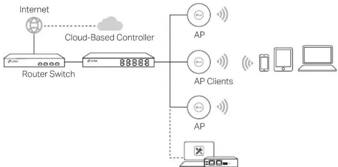
A typical network topology for the AP is shown below
flowchart
graph LR
    A["Internet"] --> B["Cloud-Based Controller"]
    B --> C["Router Switch"]
    C --> D["AP Clients"]
    C --> E["AP"]
    D --> F["Mobile Device"]
    E --> G["Computer"]
Software/Hardware Controller
Some APs can be configured and monitored centrally via a controller. For details, refer to the product specifications and the manual for the relevant product or controller. You can get the controller from https://www.tp-link.com or contact the sales staff
Hardware Installation
■ Option 1: Ceiling Mounting
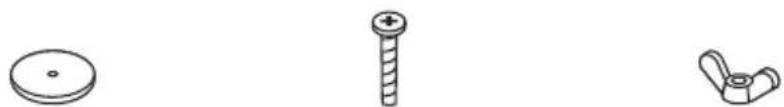
Follow the steps below to install the AP with the provided accessories:
Note: The mounting bracket and the accessories (quantity and size) may vary by product
natural_image
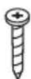
Three technical line drawings of mechanical parts: a circular plate, a threaded screw, and a curved knob (no text or symbols)Washers Pan-head Screws Wing Nuts
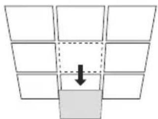
1 Remove the ceiling tile
natural_image
Diagram showing a grid of empty squares with one highlighted by a downward arrow (no text or symbols)2
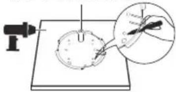
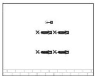
Place the mounting bracket in the center of the ceiling tile Mark positions for the screw holes and a position for the Ethernet cable hole Drill holes for the screws and a hole for the Ethernet cable at the marked positions
3
Secure the mounting bracket to the ceiling tile using pan-head screws, washers and wing nuts
4
Feed the Ethernet cable through the hole and set the ceiling tile back into place
5
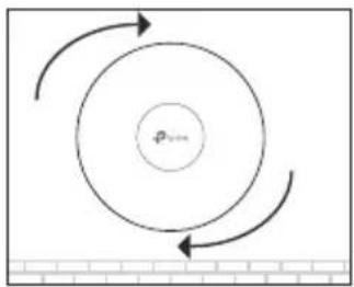
Connect the Ethernet cable to the Ethernet port Attach the AP to the mounting bracket by aligning the arrow mark on the AP with the arrow mark on the mounting bracket, then rotate the AP until it is locked into place
Hole for Ethernet cable
natural_image
Diagram showing a tool interacting with a circular object on a flat surface, with an inset magnified view of the tool's tip (no text or symbols present)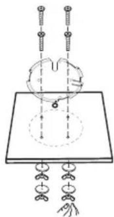
natural_image
Diagram of a mechanical setup with pulleys, weights, and a central rotating component (no text or labels)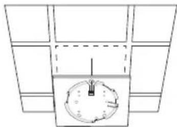
natural_image
Top-down schematic of a circular object with internal lines and arrows, enclosed in a divided rectangular frame (no text or symbols)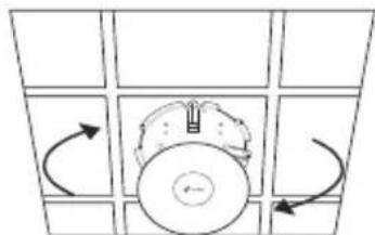
natural_image
Diagram of a circular object with directional arrows indicating rotation or movement, surrounded by grid panels (no text or symbols)■ Option 2: Wall Mounting
Follow the steps below to install the AP with the provided accessories:
Note: The mounting bracket and the accessories (quantity and size) may vary by product
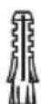
Plastic Wall Anchors Self-tapping Screws
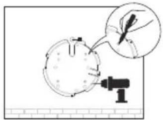
If your Ethernet cable feeds through the wall, position the mounting bracket and feed the Ethernet cable Mark positions for the screw holes and then drill holes at the marked positions
natural_image
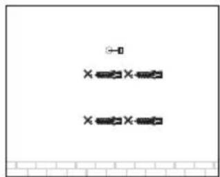
Illustration of a hand holding a plant with a magnified view of the leaf being inserted into a container (no text or symbols)2 Insert the plastic wall anchors into the holes
natural_image
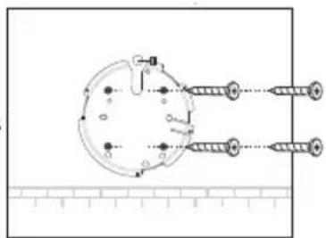
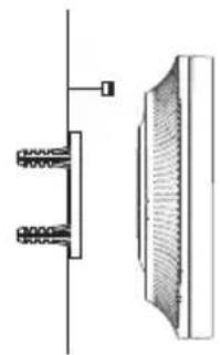
Pure electrical circuit lines without any symbols3 Secure the mounting bracket to the wall by driving the self-tapping screws into the anchors Make sure that the shoulders of the mounting bracket are on the outside
4 Connect the Ethernet cable to the Ethernet port on the AP
natural_image
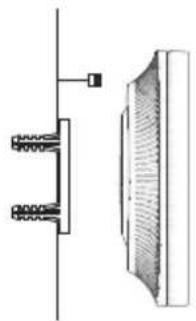
Technical line drawing of a mechanical component with spring-loaded parts and a textured cylindrical part (no text or symbols)5 Attach the AP to the mounting bracket by aligning the arrow mark on the AP with the arrow mark on the mounting bracket, then rotate the AP until it is locked into place
natural_image
Diagram showing a circular flow with arrows indicating direction, no text or symbols presentPower Supply
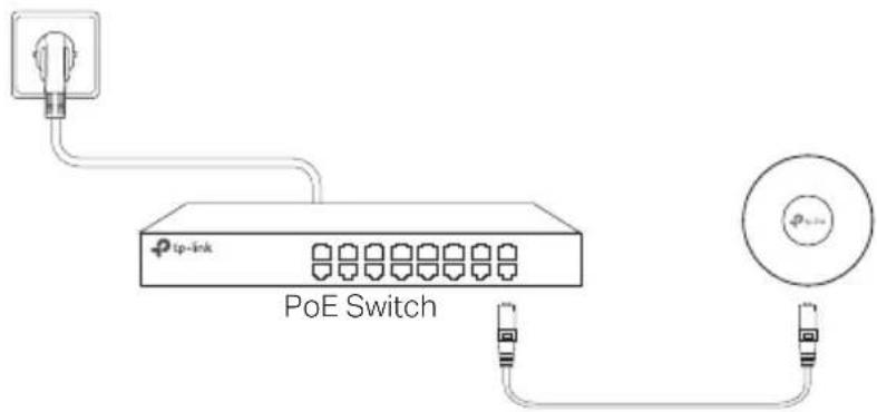
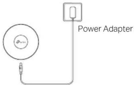
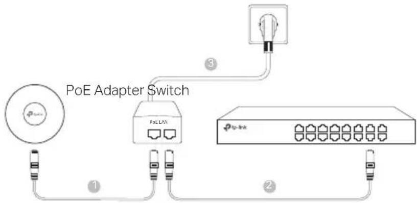
■ Power via PSE Device or Power Adapter
Some APs can be powered via the power adapter or the PSE device (such as a PoE switch) which complies with Power Source Class 2 (PS2) or Limited Power Source (LPS) of IEC 62368-1
Note: Availability depends on the actual product Please refer to the product specifications
Via PoE Switch
Via Power Adapter
■ Power via PoE Adapter
Some APs can be powered via the PoE adapter
Note: Availability depends on the actual product Please refer to the product specifications
natural_image
Diagram showing a grid of 10 empty squares with one filled in gray, and a downward arrow pointing to the bottom-right square (no text or symbols)2
natural_image
Top-down schematic of a clock face with no text or symbols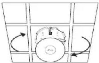
natural_image
Diagram of a circular object with rotational arrows, no text or symbols presentnatural_image
Illustration of a hand holding a leaf next to a circular object with a tool, no text or symbols presentnatural_image
Pure electrical circuit lines without any symbolsnatural_image
Technical diagram showing a mechanical assembly with two vertical components and a shaded cross-sectional view (no text or symbols)natural_image
Diagram showing a grid of 10 empty squares with one filled in gray, and a downward arrow pointing to the bottom-right square (no text or symbols)natural_image
Top-down schematic of a mechanical or electrical component with no visible text, numbers, or symbolsnatural_image
Diagram of a circular component with directional arrows indicating rotation or movement, surrounded by grid-like panels (no text or symbols)natural_image
Illustration of a hand holding a plant with a magnified view of the leaf being inserted into a container (no text or symbols)natural_image
Pure electrical circuit lines without any symbolsnatural_image
Technical diagram showing a mechanical assembly with two spring-loaded components and a textured panel (no text or symbols)natural_image
Diagram showing a circular flow with arrows indicating direction, no text or symbols presentAlimentation
natural_image
Diagram showing a grid of empty squares with one highlighted by a downward arrow (no text or symbols)2
natural_image
Simple line drawing of a clock with an hour, no text or symbols present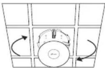
natural_image
Diagram of a circular device with directional arrows indicating rotation or movement (no text or symbols)natural_image
Diagram showing a hand holding a small object near a circular object, with a tool nearby (no text or symbols present)2 Insira as buchas de parede de plástico nos furos
natural_image
Simple diagram with three horizontal lines and a small circle, no text or symbols presentnatural_image
Pure mechanical diagram showing a circular component with two threaded fasteners and a ruler for scale (no text or symbols)4 Conecte o cabo Ethernet à porta ETHERNET no AP
natural_image
Technical line drawing of a mechanical component with spring-loaded parts and a curved housing (no text or symbols)For technical support, the user guide and other information, please visit https://www tp-link com/support/?type=smb, or simply scan the QR code.