712510 - Freezer Cool Head - Free user manual and instructions
Find the device manual for free 712510 Cool Head in PDF.


User questions about 712510 Cool Head
0 question about this device. Answer the ones you know or ask your own.
Ask a new question about this device
Download the instructions for your Freezer in PDF format for free! Find your manual 712510 - Cool Head and take your electronic device back in hand. On this page are published all the documents necessary for the use of your device. 712510 by Cool Head.
USER MANUAL 712510 Cool Head
natural_image
Exterior view of a white stainless steel cooling unit with open door, fan compartments, and digital display (no visible text or symbols)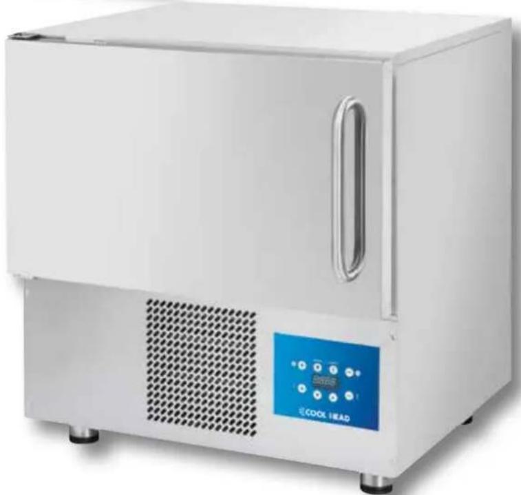
natural_image
White laboratory appliance with a blue control panel and ventilation grille (no visible text or symbols)
INSTRUCTION MANUAL

MANUEL DE INSTRUCTIONS

BEDIENUNGSANLEITUNG
EMGA
English
Overall terms
1- GENERAL INFORMATIONS 52
1.1 - RISK ANALYSIS 53
1.2 - MACHINERY PLACEMENT and UNPACKING 54
1.3 - INTENDED USE 54
1.4 - ELECTRICAL CONNECTION 55
1.5 - APPLICATIONS 56
1.6 - TECHNICAL ASSISTANCE 57
1.7 - IDENTIFICATION & BRANDING 57
1.8 - COMPONENTS IDENTIFICATION 58
1.9 - CLEANING 59
1.10 - MACHINERY DISPOSAL 59
Operating Instructions
2 - HUMAN INTERFACE and CYCLES 61
3 - FOOD PROBE 62
4 - OPERATING CYLCES 63
4.1 - START UP 64
4.2 - SHUTDOWN 64
4.3 - AUTOMATIC BLAST CHILLING CYCLE 65
4.4 - MANUAL BLAST CHILLING CYCLE 66
4.5 - AUTOMATIC SHOCK FREEZING CYCLE 70
4.6 - MANUAL SHOCK FREEZING CYCLE 71
4.7 - THAWING CYCLE 75
4.8 - DEFROSTING CYCLE 79
4.9 - EXPORT HACCP 80
4.10 - STERILIZATION (OPTIONAL) 81
5 - MENU' INFO-ESC 82
5.1 - I/O 83
5.2 - ACTIVE ALARMS 84
5.3 - LANGUAGE 85
5.4 - TIME 86
5.5 - ALARMS LIST 87
Troubleshooting
6- ALARMS CHART 89
FRANÇAIS
INDICATIONS GÉNÉRALES
1- INFORMATIONS GÉNÉRALES 92
1.1 - ANALYSES DES RISQUES 93
1.2 - MISE EN PLACE ET DÉBALLAGE 94
1.3- USAGE PRÉVU 94
1.4- BRANCHEMENT ÉLECTRIQUE 95
1.5 - INDICATIONS D'UTILISATION 96
1.6 - ASSISTANCE TECHNIQUE 97
1.7 - IDENTIFICATION ET MARQUAGE 97
1.8 - IDENTIFICATION DES PIÈCES 98
1.9 - NETTOYAGE 99
1.10 - DÉMANTÈLEMENT DE L'APPAREIL 99
INSTRUCTIONS DE FONCTIONNEMENT
1- GENERAL INFORMATIONS
The information in this documentation provide important notions about the safety, the use and the maintenance of the equipment. To always maximize the safety, the hygiene and the functionality of the machinery, it is advisable to carefully keep all the documentation near the appliance and to deliver it to the technicians and operators responsible of its use.
The choice of the materials and the products construction comply with the CE safety directives, also a 100% testing of each machineries guarantee the quality of this equipment.
The observation of the recommendations contained in this manual is essential for the safety of the installation / commissioning of the machine and of the final user.
The manufacturer, the dealer and the authorized service centers are available to clarify any questions on the use and installation of the equipment.
The manufacturer reserves the right to make changes without notice in order to achieve the improvements deemed necessary.
FAILURE TO OBSERVE THE PROVIDED INSTRUCTIONS MAY AFFECT THE SAFETY OF THE EQUIPMENT AND IMMEDIATELY VOID THE WARRANTY.
ALL THE ELECTRIC APPLIANCES CAN BE HAZARDOUS TO YOUR HEALTH. REGULATIONS AND LAWS MUST BE RESPECTED DURING THE INSTALLATION AND THE USE OF SUCH EQUIPMENTS.
ALL THE INSTALLATION OPERATIONS, MAINTENANCE, ADJUSTMENT AND REPAIRS MUST BE PERFORMED BY QUALIFIED SERVICE PERSONNEL.
THE PROPER OPERATION AND THE DURATION OF THE EQUIPMENT DEPEND ON PROPER PREVENTIVE MAINTENANCE PERFORMED EVERY 4 MONTHS BY QUALIFIED SERVICE PERSONNEL.
This manual is an integral part of machinery and as such must be preserved for the whole life of the unit.
The manufacturer is relieved from any liability in the following cases:
- Improper use of the machine:
- Improper installation, without following the procedures contained herein;
- Power supply defects;
- Serious shortcomings in the planned maintenance;
- Unauthorized modifications or interventions;
- Use of spare parts non original or non suitable for the model;
- Total or partial disregard of the instructions.
The manual in rev. 04 contains the following additions / modifications / corrections:
Chapter 1.2 : - The Machines must be installed, tested and maintained in full compliance with safety laws, the enforced laws and regulations. The installer is required to check any restrictions imposed by local authorities.
Chapter 1.4: - There must be available, for the connection, an all-pole type main switch which cuts off all contacts including neutral, with a distance between the open contacts of at least 3 mm, with circuit safety braker and coupled to fuses, to be sized or calibrated in according to the power indicated on the machinery identification plate.
- ATTENTION: In order to avoid any danger deriving from an automatic reset of the thermal protection of the compressor, the equipment must not be powered by switching devices such as switches, relays, timers or connected to circuits that are open and closed regularly by hand.
- Verify the integrity of the power cord, if it is damaged, have it replaced by qualified personnel.
Chapter 1.6: - Maximum load allowed for each shelf: 5 Kg
- For climate class 5 compliance testing to EN 60335-2-89 (chapters 10,11,13) are made at an ambient temperature of 43^ ± 1^ . For climate class 4 compliance testing are made at 32^ ± 2^ .
- Do not store explosives, such as pressurized containers with flammable propellant in this device.
Further details can be found in the relevant information chapters.
1.1 - RISK ANALYSIS
Hazards list:
- Electrical components
- Sharp parts
- Machinery handling
- Fans in motion
- Refrigerant gases
- Air Flow
- Non-potable water
- Food contamination
- Not accessible gas pipes
- Cold environments
Warnings related to the danger of electrical components. Risk of electric shock, burns, or fire:
- Access to the electrical components must be performed only by qualified technicians.
- Do not touch the machinery with damp or wet hands or feet.
- Do not operate the machinery when barefoot.
- Do not insert fingers, objects or tools through the louvers or vents.
- Do not pull the power cord.
- Do not wash the machine with water jets or steam.
- Before carrying out any maintenance or cleaning operation, disconnect the machinery from the main power supply by turning off the main switch and unplugging the power cord.
- If the room where the machinery is located becomes flooded, contact an authorized service center for repair before using the machinery again.
- If the machinery is not used, disconnect it from the main power supply.
Warnings related to general hazards. Risk of injury:
- Presence of sharp edges. For operations on the machinery use suitable protective gloves.
- The handling of the machinery must be safely performed with means and attention such as to prevent damage to people and property.
- Presence of moving fans. Do not remove the protective grids.
- Read in the machinery identification plate the type of refrigerant gas, it could be a flammable gases.
- In case of flammable gas leaks from the cooling system of the machinery, unplug the power cord, open the windows to ventilate the room and call for service immediately.
- If the refrigerant gas leaks, do not touch or inhale the leaked gas.
- After the first installation or any repair operations of the machinery, always check that there is no refrigeration gas leakage.
- Presence of air flows. Do not directly expose people to cold or warm air flows.
- Do not block the inlet or outlet of the air flow.
- Presence of non-potable water. Do not drink the water drained from the machine.
- To prevent the contamination of food, the latter must not come into direct contact with the machinery but placed in appropriate containers.
- Presence of gas pipes with high or low temperatures. Before touching the pipes make sure what is their temperature. Use suitable protective gloves.
- Presence of parts in plexyglass. Do not hit those parts.
- In case of noise, odors or smoke unusually coming from the machinery, unplug the power cord and contact your authorized service center.
- Do not install the machinery in places directly exposed to sea air or under direct sunlight.
1.2 - MACHINERY PLACEMENT and UNPACKING
The Machines must be installed, tested and maintained in full compliance with safety laws, the enforced laws and regulations. The installer is required to check any restrictions imposed by local authorities.
Things to avoid :
- Places exposed to direct sunlight.
- Closed sites with high temperatures and poor air exchange.
Remove the protective film from all sides.
For a good installation of the machinery with air-cooled condenser built into the motor compartment, you must ensure that in the installation area nothing is obstructing the air vents necessary for the proper functioning of the machinery or of the premises itself. Keep a minimum distance of 50 cm from the air inlet and outlet sides.
The machinery must be installed and leveled by adjusting the support feet, so as to ensure stability; any other different installation solutions must be agreed and approved by the manufacturer. For the leveling of the heavy machinery, use special lifters.
If the equipment is not leveled, its operation and the flow of condensed water can be compromised.
If the cabinet is supplied on wheels, place it on a level surface and block them before switching on the equipment.
If the machine is of modular type of cell with bottom panel placed on the floor, it is necessary to fix the bottom panel to the floor with appropriate brackets (not supplied) and to seal it using specific silicone.
If the machine is of modular type of cell with bottom panel built-in in the floor, it is necessary to provide and guarantee the air flow under and at the edges of the floor to avoid the formation of condensation water.
For the movement of the machinery, it is not recommended to incline it or to recline it. If for any reason this operation is necessary, wait 24 hours after positioning the machine before starting it up, thus allowing the oil to return to the compressor and preventing it from breaking.
Before removing the packaging, check that it is intact, disputing and writing on the delivery note of the forwarding agent any damage noted before signing it. After removing the packaging, check that the machinery is intact; in the event that it is damaged, immediately notify the dealer by fax or registered mail with proof of delivery and if the damage is likely to jeopardize the safety of the machine, do not proceed with the installation until the intervention of a qualified technician.
All packaging (plastic bags, cardboard, nails, etc.) must not be left within reach of children and pets as a source of potential danger.
1.3 - INTENDED USE
Blast chillers and shock freezing units are appliances needed to cool down the food quickly, to avoid the proliferation of bacteria in the food and to maintain the quality and flavor of the foods to be cooled.
These machineries are used in three different modes:
- Blast chilling to bring the food temperature to +3°C.
- Shock freezing to bring the food temperature to -18^ C.
- Thawing to bring the food temperature around +10°C.
The blast chiller user can set the more appropriate working cycle in relation to the operations he wants to perform.
Blast chillers and shock freezing machineries, at the end of each cycle, can also preserve the food at a specific and constant temperature, but only for a limited time, not longer than 2 days.
In fact, these machineries are not intended as a temperature storing up appliances.

1.4 - ELECTRICAL CONNECTION
THE EQUIPMENT IN THE 400V 3 PHASE POWER SUPPLY VERSION IS PROVIDED WITHOUT THE PLUG TO BE CONNECTED TO THE POWER LINE.
THE PRODUCER DISCLAIMS ANY RECOURSE IN CASE THE CONNECTIONS ARE MADE BY THE USER OR BY NOT QUALIFIED PERSONNEL.
- Verify the integrity of the power cord, if it is damaged, have it replaced by qualified personnel.
- The power supply must be compatible with the indications given in the wiring diagram of the machine.
- There must be available, for the connection, an all-pole type main switch which cuts off all contacts including neutral, with a distance between the open contacts of at least 3 mm, with circuit safety braker and coupled to fuses, to be sized or calibrated in according to the power indicated on the machinery identification plate.
- The main power switch must be on the electric line near the installation and must serve exclusively one apparatus at a time.
- There must be already available and in use, an efficient GROUNDING system to which connect the machine.
- The use of adapters, multiple sockets, wires with a not suitable section or with extension connections not complying with the specific law requirements, it is forbidden.
- For any details on the electrical operation for the machinery, consult the electrical diagram attached to the machinery.
- The power cord can not be put into traction or crushed during normal operation or the ordinary maintenance.
To be noted that the models listed below can only be installed in rooms whose electrical system has maximum impedance values as shown in the table:
| SPEED 5T Zmax = 0,40 Ω |
| SPEED 8T Zmax = 0,22 Ω |
| FASTER 15T Zmax = 0,40 Ω |
ATTENTION: In order to avoid any danger deriving from an automatic reset of the thermal protection of the compressor, the equipment must not be powered by switching devices such as switches, relays, timers or connected to circuits that are open and closed regularly by hand.

1.5 - APPLICATIONS
-Do not overlap the food you want to blast chill or freeze.
-Do not exceed the declared maximum allowed weights for each shelf, but distribute the product in trays in a uniform manner.
-Blast chilling and freezing times always refer to products maximum 40 mm thick.
-Always blast chill one type of food per time, different food have different densities and therefore the cycle timing and output can change.
-Maximum load allowed for each shelf: 5 Kg
-The food probe must be placed correctly in the middle of the largest food type and the tip should never exit the food and/or touch the pan.
-To avoid the probe breaking, do not insert it in food with a temperature higher than 100^ C.
-The food probe must always be cleaned after each use or malfunctioning.
-Do not cover the food with lids or other means, the more you isolate the food, the longer the cycle time will be.
-If you insert foods at temperatures above 70^ C there is a risk of overloading the machine, increasing the cycle time and the power consumption.
-Do not block the fans vents.
-The water discharge pot contained in the chiller cell must be placed under the equipment in its rails
-Be careful that the drain tube has to be placed inside the container and free from any obstructions.
-The pot must be emptied out regularly; to perform this operation, you just have to remove the pot from its rails, empty it and then place it back on the rails
-Maximum allowed load on each shelf is 20 Kg.
-For climate class 5 compliance testing to EN 60335-2-89 (chapters 10,11,13) are made at an ambient temperature of 43^ ± 2^ . For climate class 4 compliance testing are made at 32^ ± 2^ .
-The machineries with incorporated condensing unit are not built-in devices.
-Do not store explosives, such as pressurized containers with flammable propellant in this device.
-The model 3T complies with EN 61000-3-3 standard.
Below is the table showing the energy consumption of the various models of blast chillers and freezers.
Blast chilling cycle: Manual with Air set at -25°C
Shock freezing cycle: Manual with Air set at -40°C
| Model | Blast chilling energy consumptionkWh/Kg | Shock free-zing energy consumptionkWh/Kg | Blast chilling yieldKg | Shock free-zing yieldKg | Gas charge R404A (GWP 3922)R452A (GWP 2141)Kg | Blast chilling cycle time(+65°C ÷ +10°C)min | Shock freezing cycle time(+65°C ÷ -18°C)min |
| 3T 0,056 | 7 0,0729 9 7 0 | ,5 90 270 | |||||
| 5T small 0,0434 0,0530 | 11 | 9 0,6 90 270 | |||||
| 5T | 0,0299 | 0,0449 | 15 | 10 | 0,6 | 90 | 270 |
| 8T 0,027 | 5 0,0385 | 21 | 15 | 1,2 90 270 | |||
| 10T | 0,0281 | 0,0409 | 32 | 22 | 1 | 90 | 270 |
| 15T | 0,0566 | 0,0809 | 40 | 28 | 1,8 | 90 | 270 |
| 20T | 0,0406 | 0,0650 | 80 | 50 | 3,5 | 90 | 270 |
| 40T | 0,0284 | 0,0454 | 160 | 100 | 7 | 90 | 270 |

1.6 - TECHNICAL ASSISTANCE
The after-sales technical assistance is guaranteed by the manufacturer through its network of resellers - dealers and installers. For technical assistance, contact an authorized dealer, providing the identification data, available on the identification plate.
1.7 - IDENTIFICATION & BRANDING
| MOD. | |||||||
| CODICE CODE | ……… | MATR. S/N | ……… | ||||
| ALIMENTAZIONE RATED VOLTAGE | ……… | (V) | ……… (Hz) | ……… | (W) | ……… | (A) |
| SBRINAMENTO (W) DEFROSTING | ……… | ||||||
| REFRIGERANTE COOLING GAS | ……… | MASSA (Kg) QUANTITY | ……… | ||||
| CLASSE CLIMATICA CLIMATIC CLASS | Max Pressure Gas | ||||||
| GAS ISOLAMENTO FOAMING GAS | HFO-1234ze / CO2 / 245fa | 25 BAR | |||||
| ORDINE CONFIRM NR. | ANNO YEAR | ……… | |||||
Figure 1 - Example of a nameplate applied to the machine.
For a correct consultation of this manual, identify the model in your possession through the informations on the identification label.
The machine is identified by the following parameters:
Serial number
Technical specifications
Production year
The installation and the use of the machinery must comply with the nameplate data and indications on the technical data sheets.

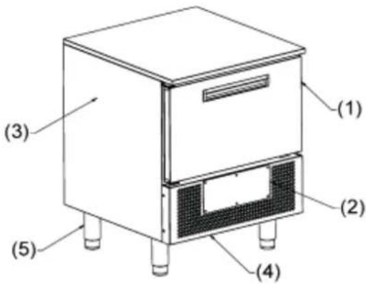
1.8 - COMPONENTS IDENTIFICATION
text_image
(1) (2) (3) (4) (5)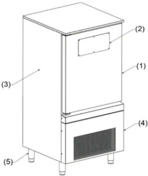
text_image
(1) (2) (3) (4) (5)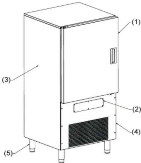
text_image
(1) (2) (3) (4) (5)| (1) DOOR (4) MOTOR COMPARTMENT | |
| (2) CONTROL PANEL (5) FEET/CASTORS | |
| (3) REFRIGERATED COMPARTMENT |
1.9 - CLEANING
DO NOT USE WATER JETS EVEN PRESSURIZED OR STEAM.
CLEANING THE EXTERNAL MODULE
It must be performed with a damp cloth with a solution of water and bicarbonate, or other neutral cleaners, dry with a soft cloth.
CLEANING THE DISPLAY: "GLASS"
It must be performed using a clean soft cloth (free from dust and slag), moistened with soap and water or water and alcohol at 10% max. Other cleaners or cloths not wetted or soiled, could ruin the material. Dry it with a clean soft cloth.
CLEANING THE INNER CELL
Remove the pans, grids and guides can be cleaned as the interior, clean with a damp cloth with a solution of water and bicarbonate, or other neutral cleaners, dry with a soft cloth.
CLEANING OF THE FOOD PROBE
After each blast chiller cycle in which the core probe has been used, you must clean it with a damp sponge with a solution of water and bicarbonate.
CLEANING THE CONDENSER (MAINTENANCE)
For a correct operation of the machinery it is necessary that the condenser is kept clean to allow free circulation of air. This operation has to be done every 120 days at the most. It must be done with a soft bristle brush to remove all dust and fluffs that are deposited on the fins of the condenser.
It would be even better to use a vacuum cleaner to avoid the release in the environment of the removed dust.
In presence of greasy deposits, you may want to remove them using a brush dipped in alcohol.
1.10 - MACHINERY DISPOSAL
The scrapping and the final disposal of the machinery must be made following the regulations in force in the country of installation, especially with regards to the refrigerant gas and the lubricating oil of the compressor.
Materials used in the construction of the machinery:
Stainless steel: Construction of the appliance
Plastic parts: Construction of various parts
Refrigerant gas: in the refrigerant circuit
Compressor oil: in the refrigerant circuit
Copper: electrical system and the cooling circuit.

natural_image
Symbol of a trash bin crossed with no text or labels
IT08020000000615
Below are the information for the user for the correct handling of electric and electronic devices (WEEE):
- There is an obligation not to dispose WEEE devices as unsorted municipal waste and to have for such waste a separate collection;
- For the disposal, you should use only public or private waste collection systems defined by the local legislation. It is possible to return to the distributor the equipment at the end of its working life only when buying a new equipment;
- This equipment may contain hazardous substances: the improper use or incorrect disposal may have negative effects on human health and on the environment;
The symbol (crossed out waste bin) shown on the product and in the above picture indicates that the equipment has been introduced onto the market after 13 August 2005 and must be disposed of separately; - In the event of illegal disposal of electrical and electronic waste, the fines are specified by the local regulations regarding disposal.

Operating Instructions

2 - HUMAN INTERFACE and CYCLES





The models are supplied with a main power electronic board "Compact" and with a capacitive display "Glass". The user interface has a 6 led digits display with scrolling messages and it also has 6 capacitive buttons, divided as follows:


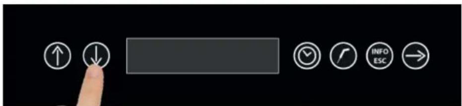
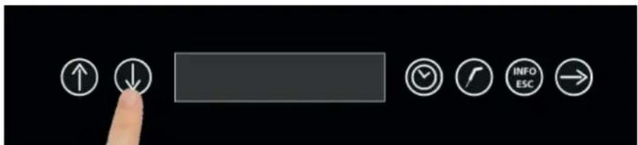
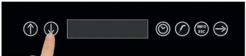
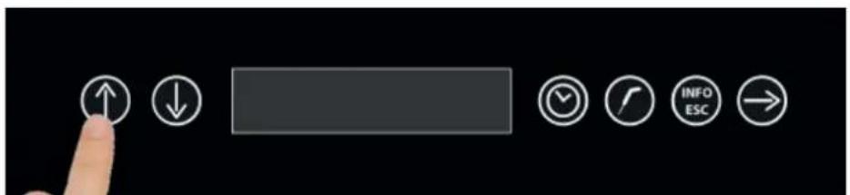
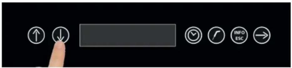
UP and DOWN buttons : buttons to select the machinery cycles ( with DOWN button from 1 to 8 ):
1- Automatic blast chilling
2- Manual blast chilling
3- Automatic shock freezing
4- Manual shock freezing
5- Thawing
6- Defrosting
7- Export HACCP
8- Sterilization (optional)


Cycle buttons : buttons to select the options for the manual cycles : time or temperature
Furthermore, the "Clock" button, when the machinery is signalling the end of a cycle or an alarm, if pressed, it ends the Buzzer

INFO-ESC button : button to select the settings menu, to end a cycle and to save the configuration parameters:
1- I/O (also displayed during a cycle)
2- Active alarms (also displayed during a cycle)
3- Language
4- Time
5- Alarms list
6- S/N
7- Parameters
8- Software
9- Scanner
10- Reset

CONFIRMATION button : button to confirm the selections, start a cycle and exit from the finished
cycle,
machinery start up and shutdown.

3 - FOOD PROBE
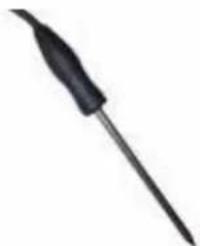
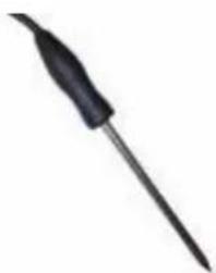
The food probe or hat pin probe, has a resolution of 0.1 °C and an operating range from -49.9 °C to +99.9 °C . The temperature detection is carried out on a single point in correspondence of the central part of the probe body. To ensure proper operation and accurate detection of the temperature for the management of cycles, the probe must be inserted up to the product core.
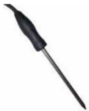
natural_image
Close-up of a black soldering iron with a pointed tip (no text or symbols visible)
natural_image
Steamed flat pan with heart-shaped decoration on a dark surface (no text or symbols visible)
4 - OPERATING CYLCES
The blast chiller can manage the following operating cycles :
1- Automatic blast chilling
2- Manual blast chilling
3- Automatic shock freezing
4- Manual shock freezing
5- Thawing
6- Defrosting
7- Export HACCP
8- Sterilization (optional)
Please note that the blast chilling or the shock freezing cycles are designed to rapidly cool the food and the difference between the two cycles is determined by the final temperature you want to obtain to the heart of food:
- BLAST CHILLING positive = final positive temperature in the around of +3°C
- SHOCK FREEZING negative = final negative temperature in the around of -18°C
The defrosting cycle, has the function of bringing a food from negative temperatures to positive temperatures. To be noted that the positive air temperature is not obtained by heating, but by air circulation within the terms required by the HACCP.
The machinery has an innovative cell PRE-COOLING function, with an indeterminate duration at the discretion of the user who will decide when to start the blast chilling or the shock freezing cycles. Bringing the cell air temperature to a much lower temperature than the surrounding environment before starting any cycle, allows not only to reduce the total cycle time, but also to obtain a correct and uniform micro-crystallization of the food resulting in a reduced product weight loss and guaranteeing the organoleptic characteristics similar to the fresh product.
Following are the main characteristics for each single operating cycle:
1- AUTOMATIC BLAST CHILLING : Automatic cycle with temperature detection exclusively through food probe
2- MANUAL BLAST CHILLING : Manual cycle adjustable for the following values:
time : cycle duration and cell air temperature
temperature : product final temperature and cell air temperature
3- AUTOMATIC SHOCK FREEZING : Automatic cycle with temperature detection exclusively through food probe
4- MANUAL SHOCK FREEZING : Manual cycle adjustable for the following values:
time : cycle duration and cell air temperature
temperature : product final temperature and cell air temperature
5- THAWING : Manual cycle adjustable for the following values:
time : cycle duration and cell air temperature
temperature : product final temperature and cell air temperature
6- DEFROSTING : Automatic cycle only with AIR with time set to 600 seconds with the aim at cleaning the evaporator.
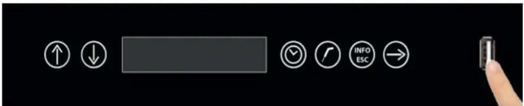
7- EXPORT HACCP : Using the USB door on the front panel on the right side of the CONFIRMATION button, it is possible to export the HACCP data approximately for the operations of a complete month (120 hours of operations).
8- STERILIZATION (OPTIONAL) : Cycle available only with the optional sterilizer. Automatic cycle with time set to 300 seconds with ventilation function.
4.1 - START UP
After connecting the machinery to the power supply, the display will show the STAND-BY writing, that writing indicates that the machinery is at rest, which means that it is not possible to access the selection menu.
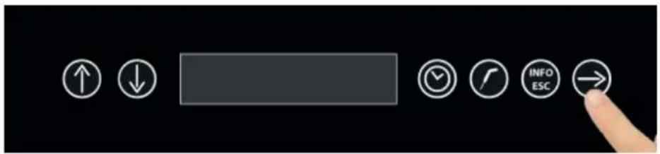
To turn on the blast chiller keep pressed the CONFIRMATION button for at least 3 seconds.
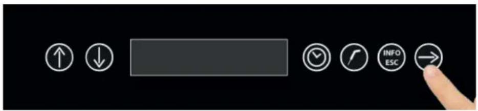
text_image
User interface toolbar with directional buttons and a finger pointing to the right buttonThe display will then show the message STOP which indicates : Machinery waiting for the cycle selection.
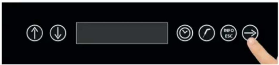
4.2 - SHUTDOWN
Keep pressing the CONFIRMATION button for at least 3 seconds to enter the STAND-BY mode.
text_image
User interface toolbar with directional buttons and a finger pointing to the right button
4.3 - AUTOMATIC BLAST CHILLING CYCLE
The automatic blast chilling cycle requires only the use of the food probe.
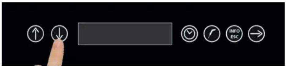
With the machinery in STOP mode :
text_image
User interface toolbar with navigation and function icons including up/down arrows, checkmark, clock, and directional buttonsPress the UP and DOWN buttons to select the cycle 1 AUTOMATIC BLAST CHILLING.
text_image
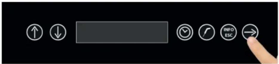
User interface toolbar with directional buttons and a finger pointing to the right buttonTo select this cycle, press the CONFIRMATION BUTTON
Once you have selected the AUTOMATIC BLAST CHILLING cycle, the machinery enters the PRECOOLING mode showing the air temperature inside the cell.
text_image
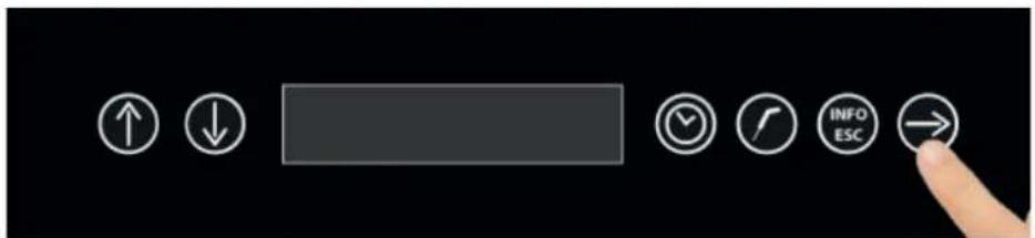
User interface toolbar with directional icons and a finger pointing to the right buttonAfter pressing the CONFIRMATION button you will be requested to insert the food probe
natural_image
Close-up of a black pen tip with a pointed tip, isolated on white background (no text or symbols)Once you have inserted the food probe and after that the machinery has detected the actual insertion of the probe, the cycle will start and the display will show BLAST CHILLING IN PROGRESS.
The cycle will end only when the temperature measured at the core will be lower or equal to the pre-set value of +3^ .
The cycle end is communicated with a buzzer that emits a sound and the time cycle button which flashes. By pressing this button, you can end the buzzer.
Once the cycle is over, the machine enters the PRESERVATION mode.
To be noted that this phase can be kept for a suggested maximum time of 8 hours.

4.4 - MANUAL BLAST CHILLING CYCLE
The manual blast chilling cycle presents the possibility to choose between the time mode, setting the duration of the cycle and the cell air temperature, or the temperature mode, setting the value of the food temperature and the cell air temperature.
A - Time manual cycle :
With the machinery in STOP mode :
text_image
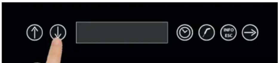
User interface toolbar with navigation and function icons including up/down arrows, checkmark, call, refresh, info, ESC, and returnPress the UP and DOWN buttons to select the cycle 2 MANUAL BLAST CHILLING
text_image
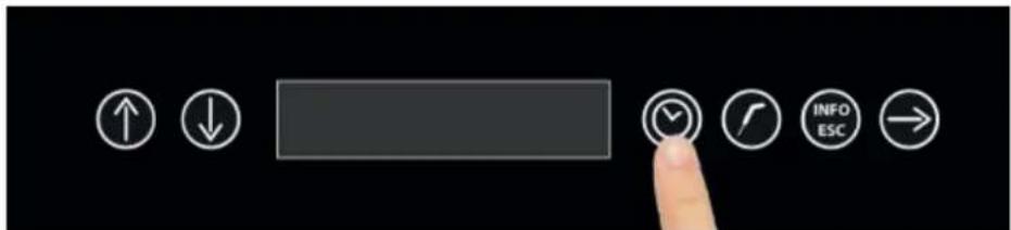
User interface buttons including up/down arrows, a blank input field, clock, refresh, info/ESC, and navigation arrowTo choose this cycle, press the CLOCK button
Once you have selected the time MANUAL BLAST CHILLING cycle, the machinery starts the PRECOOLING mode showing the value of the temperature inside the cell.
text_image
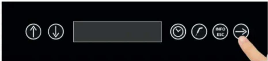
User interface toolbar with directional icons and a finger pointing to the right buttonPress the CONFIRMATION button to set the cycle duration parameter
text_image
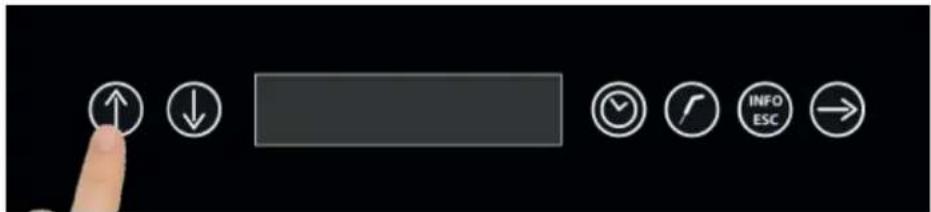
User interface toolbar with navigation buttons and a finger pointing to an up/down arrow iconSet the time value with the UP and DOWN buttons
text_image
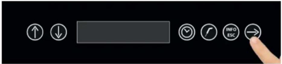
User interface toolbar with directional icons and a finger pointing to the right buttonPress the CONFIRMATION button to proceed to set the cell air temperature value

text_image
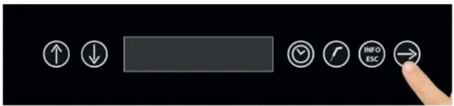
User interface toolbar with navigation and function icons including up/down arrows, a blank button, clock, refresh, info/ESC, and right-pointing arrowSet the temperature value with the UP and DOWN buttons
text_image
User interface toolbar with directional buttons and a finger pointing to the right buttonPress the CONFIRMATION button to start the cycle
The cycle starts and the display will show the message BLAST CHILLING IN PROGRESS.
The cycle will finish at the end of the set time. The cycle end is notified with a buzzer that emits a sound. Press the time cycle button to end the buzzer.
Once the cycle is finished, the machinery will start the PRESERVATION mode.
To be noticed that this phase can be maintained for a suggested maximum duration of 8 hours.

B - Temperature manual cycle :
With the machinery in STOP mode :
text_image
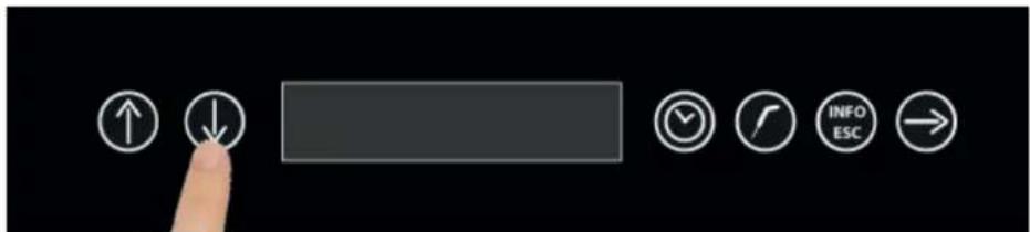
User interface buttons including up/down arrows, a blank input field, and navigation icons like checkmark, folder, info ESC, and right-pointing arrow.Press the UP and DOWN buttons to select the cycle 2 MANUAL BLAST CHILLING.
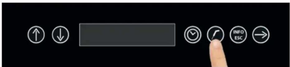
text_image
User interface toolbar with navigation and function icons including up/down, check, call, refresh, info, ESC, and right-pointing arrowTo select this cycle, press the PROBE button
Once you have selected the temperature MANUAL BLAST CHILLING cycle, the machinery starts the PRECOOLING mode showing the value of the temperature inside the cell.
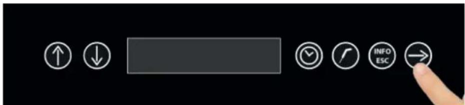
text_image
User interface toolbar with directional buttons and a finger pointing to the right buttonPress the CONFIRMATION button to proceed with the product temperature setting
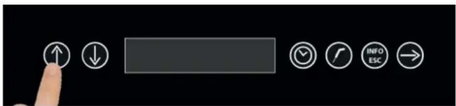
text_image
User interface toolbar with navigation buttons and a finger pointing to a buttonSet the temperature value with the UP and DOWN buttons

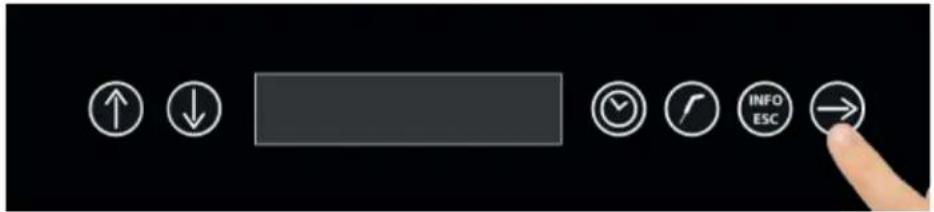
text_image
User interface toolbar with directional buttons and a finger pointing to the right buttonPress the CONFIRMATION button to proceed to set the cell air temperature value
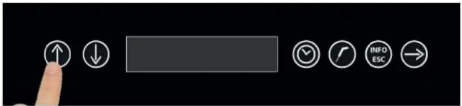
text_image
User interface toolbar with navigation and function buttons including up/down, progress bar, checkmark, refresh, info ESC, and returnSet the temperature value with the UP and DOWN buttons
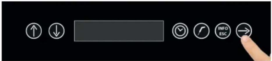
text_image
User interface toolbar with navigation and function icons including up/down, check, rotate, info ESC, and finger pointing to the right buttonAfter pressing the CONFIRMATION button you will be requested to insert the food probe
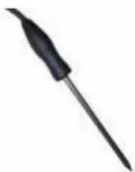
natural_image
Close-up of a black soldering iron with a pointed tip (no text or symbols visible)
Once you have inserted the food probe and after that the machinery has detected the actual insertion of the probe, the cycle will start and the display will show BLAST CHILLING IN PROGRESS.
The cycle will end only when the temperature measured at the core will be lower or equal to the pre-set value of +3°C.
The cycle end is communicated with a buzzer that emits a sound and the time cycle button which flashes. By pressing this button, you can end the buzzer.
Once the cycle is finished, the machinery will start the PRESERVATION mode.
To be noticed that this phase can be maintained for a suggested maximum duration of 8 hours.
4.5 - AUTOMATIC SHOCK FREEZING CYCLE
The Shock freezing cycle requires only the use of the food probe.
With the machinery in STOP mode:
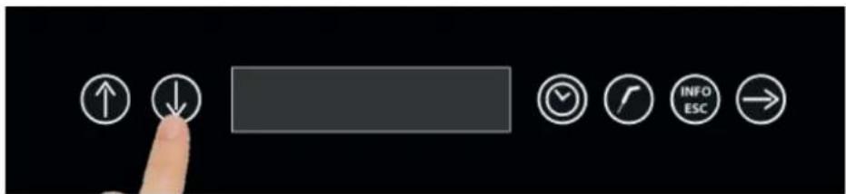
text_image
User interface toolbar with navigation and function icons including up/down arrows, checkmark, refresh, info ESC, and returnPress the UP and DOWN buttons to select the cycle 3 AUTOMATIC SHOCK FREEZING.
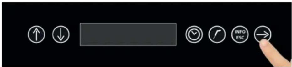
text_image
User interface toolbar with directional icons and a finger pointing to the right buttonPress the CONFIRMATION button to select this cycle
Once you have selected the AUTOMATIC SHOCK FREEZING cycle, the machinery starts the PRECOOLING mode showing the value of the temperature inside the cell
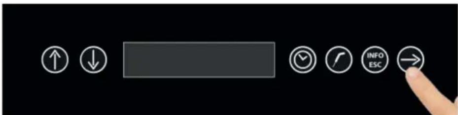
text_image
User interface toolbar with directional buttons including up/down arrows, a blank bar, clock, refresh, and navigation iconsAfter pressing the CONFIRMATION button you will be requested to insert the food probe
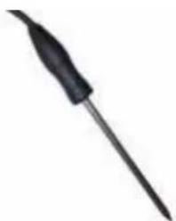
natural_image
Close-up of a black soldering iron with a pointed tip (no text or symbols visible)Once you have inserted the food probe and after that the machinery has detected the actual insertion of the probe, the cycle will start and the display will show SHOCK FREEZING IN PROGRESS.
The cycle will end only when the temperature measured at the core will be lower or equal to the pre-set value of -18^ .
The cycle end is communicated with a buzzer that emits a sound and the time cycle button which flashes. By pressing this button, you can end the buzzer.
Once the cycle is finished, the machinery will start the PRESERVATION mode.
To be noticed that this phase can be maintained for a suggested maximum duration of 8 hours.

4.6 - MANUAL SHOCK FREEZING CYCLE
The manual shock freezing cycle presents the possibility to choose between the time mode, setting the duration of the cycle and the cell air temperature, or the temperature mode, setting the value of the food temperature and cell air temperature.
A - Time manual cycle :
With the machinery in STOP mode :
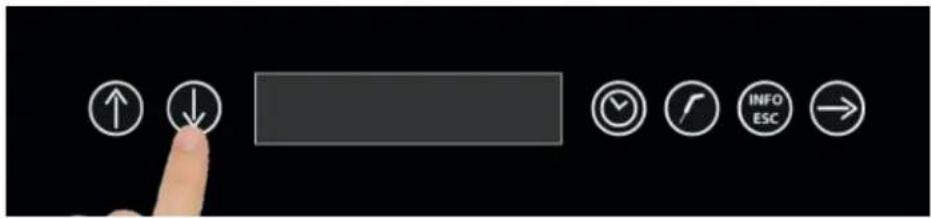
text_image
User interface toolbar with navigation and function icons including up/down arrows, a blank button, clock, refresh, info ESC, and right-pointing arrowPress the UP and DOWN buttons to select the cycle 4 MANUAL SHOCK FREEZING.
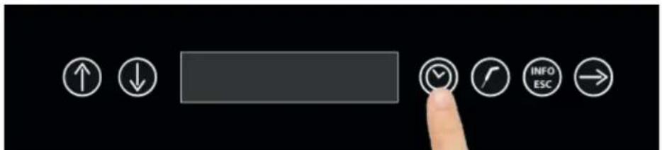
text_image
User interface buttons with directional icons including up/down arrows, a gray rectangle, and navigation icons like 'INFO ESC' and right-pointing arrow.To choose this cycle, press the CLOCK button
Once you have selected the time MANUAL SHOCK FREEZING cycle, the machinery starts the PRECOOLING mode showing the value of the temperature inside the cell.

text_image
User interface toolbar with directional buttons and navigation icons, including up/down arrows and navigation iconsPress the CONFIRMATION button to set the cycle duration parameter
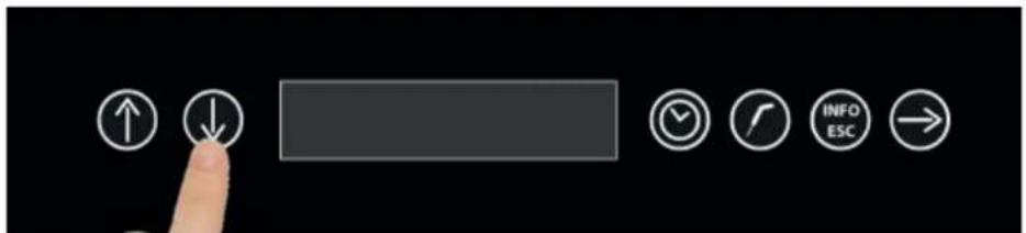
text_image
User interface toolbar with navigation and function icons including up/down arrows, a blank bar, clock, refresh, info ESC, and right-pointing arrowSet the time value with the UP and DOWN buttons
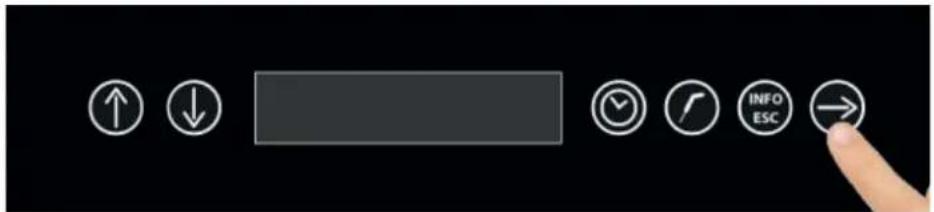
text_image
User interface toolbar with directional buttons and a finger pointing to the right buttonPress the CONFIRMATION button to proceed to set the cell air temperature value
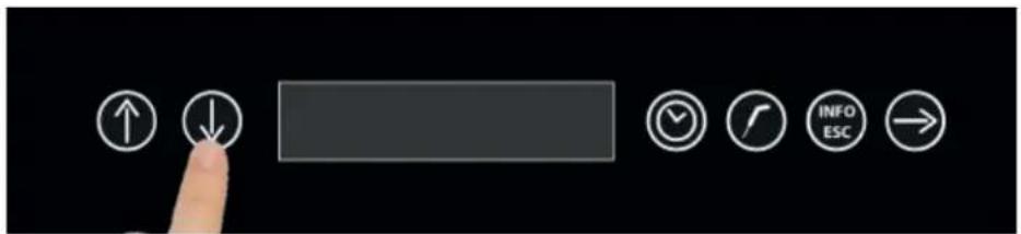
text_image
User interface toolbar with navigation and function icons including up/down arrows, checkmark, clock, refresh, info ESC, and returnSet the temperature value with the UP and DOWN buttons
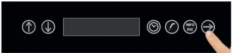
text_image
User interface toolbar with directional icons and a finger pointing to the right buttonPress the CONFIRMATION button to start the cycle
The cycle starts and the display will show the message SHOCK FREEZING IN PROGRESS.
The cycle will finish at the end of the set time. The cycle end is notified with a buzzer that emits a sound. Press the time cycle button to end the buzzer.
Once the cycle is finished, the machinery will start the PRESERVATION mode.
To be noticed that this phase can be maintained for a suggested maximum duration of 8 hours.

B - Temperature manual cycle :
With the machinery in STOP mode :
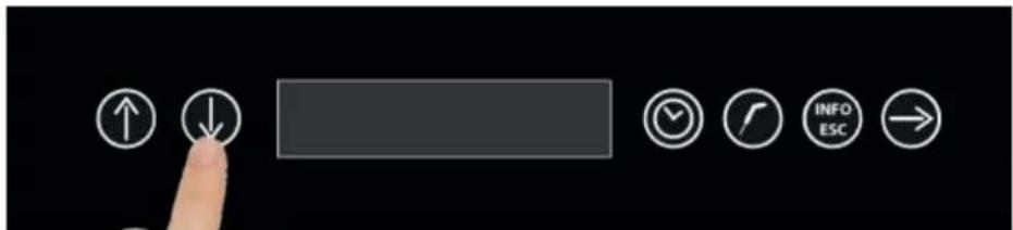
text_image
User interface toolbar with navigation and function icons including up/down arrows, checkmark, call, refresh, info, ESC, and right-pointing arrowPress the UP and DOWN buttons to select the cycle 4 MANUAL SHOCK FREEZING.

text_image
User interface toolbar with directional buttons and a finger pointing to a button labeled 'INFO ESC'To select this cycle, press the PROBE button
Once you have selected the temperature MANUAL SHOCK FREEZING cycle, the machinery starts the PRECOOLING mode showing the value of the temperature inside the cell.

text_image
User interface toolbar with directional buttons and a finger pointing to the right buttonPress the CONFIRMATION button to proceed with the product temperature setting
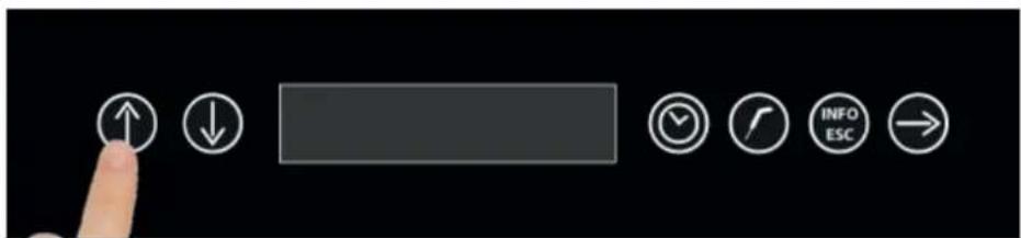
text_image
User interface toolbar with navigation buttons and a finger pointing to the buttonSet the temperature value with the UP and DOWN buttons
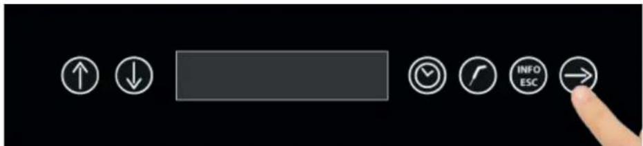
text_image
User interface toolbar with directional icons and a finger pointing to the right buttonPress the CONFIRMATION button to proceed to set the cell air temperature value
text_image
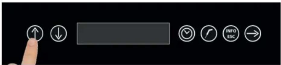
User interface toolbar with navigation and function buttons including up/down, blank bar, checkmark, folder, info ESC, and right-pointing arrowSet the temperature value with the UP and DOWN buttons
text_image
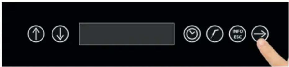
User interface toolbar with directional icons and a finger pointing to the right buttonAfter pressing the CONFIRMATION button you will be requested to insert the food probe
natural_image
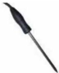
Close-up of a black soldering iron with a pointed tip (no text or symbols visible)Once you have inserted the food probe and after that the machinery has detected the actual insertion of the probe, the cycle will start and the display will show SHOCK FREEZING IN PROGRESS.
The cycle will end only when the temperature measured at the core will be lower or equal to the pre-set value of -18^ .
The cycle end is communicated with a buzzer that emits a sound and the time cycle button which flashes. By pressing this button, you can end the buzzer.
Once the cycle is finished, the machinery will start the PRESERVATION mode.
To be noticed that this phase can be maintained for a suggested maximum duration of 8 hours.

4.7 - THAWING CYCLE
The Thawing cycle presents the possibility to choose between the time mode, setting the duration of the cycle and the cell air temperature, or the temperature mode, setting the value of the food temperature and cell air temperature.
A - Manual time cycle :
With the machinery in STOP mode :
text_image
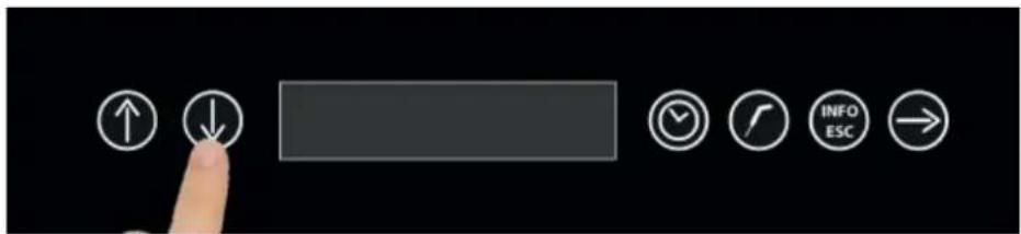
User interface toolbar with navigation and function icons including up/down arrows, checkmark, call, refresh, info, ESC, and right-pointing arrowPress the UP and DOWN buttons to select the cycle 5 MANUAL THAWING.
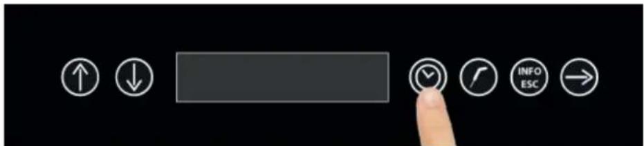
text_image
User interface buttons including up/down arrows, a blank input field, clock, tool, info/ESC, and navigation arrowTo choose this cycle, press the CLOCK button
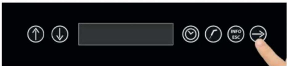
text_image
User interface toolbar with directional icons and a finger pointing to the right buttonPress the CONFIRMATION button to set the cycle duration parameter
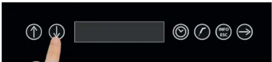
text_image
User interface toolbar with navigation and function icons including up/down arrows, checkmark, call, refresh, info, ESC, and right-pointing arrowSet the time value with the UP and DOWN buttons
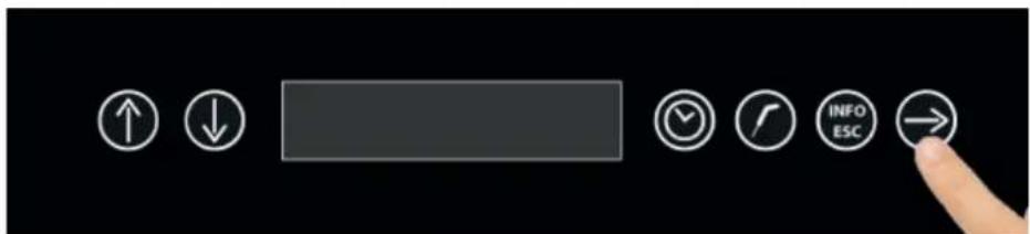
text_image
User interface toolbar with directional icons and a finger pointing to the right buttonPress the CONFIRMATION button to proceed to set the cell air temperature value

text_image
User interface toolbar with navigation buttons including up/down, down arrow, blank bar, checkmark, call, info, ESC, and right-pointing arrowSet the temperature value with the UP and DOWN buttons
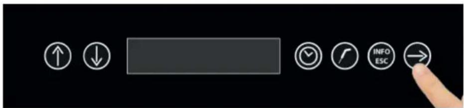
text_image
User interface buttons including up/down arrows, a blank input field, clock, refresh, info/ESC, and navigation arrowPress the CONFIRMATION button to start the cycle
The cycle starts and the display will show the message THAWING IN PROGRESS.
The cycle will finish at the end of the set time. The cycle end is notified with a buzzer that emits a sound. Press the time cycle button to end the buzzer.
Once the cycle is finished, the machinery will start the PRESERVATION mode.
To be noticed that this phase can be maintained for a suggested maximum duration of 8 hours.

B - Manual temperature cycle :
With the machinery in STOP mode :
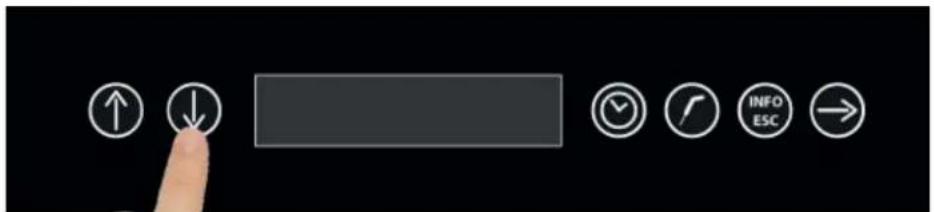
text_image
User interface toolbar with navigation and function icons including up/down arrows, checkmark, call, refresh, info, ESC, and right-pointing arrowPress the UP and DOWN buttons to select the cycle 5 MANUAL THAWING
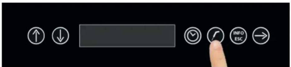
text_image
User interface toolbar with navigation and function buttons including up/down, progress bar, clock, checkmark, info ESC, and right-pointing arrowTo select this cycle, press the PROBE button
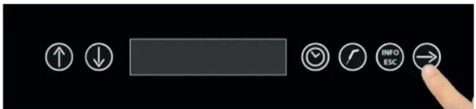
text_image
User interface toolbar with directional buttons and a finger pointing to the right button labeled 'INFO ESC'Press the CONFIRMATION button to proceed with the product temperature setting
text_image
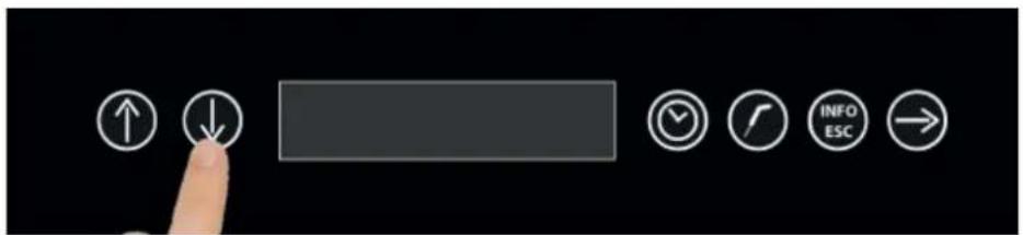
User interface toolbar with navigation and function icons including up/down arrows, checkmark, refresh, info, and ESCSet the temperature value with the UP and DOWN buttons
text_image
User interface toolbar with directional buttons and a finger pointing to the right buttonPress the CONFIRMATION button to proceed to set the cell air temperature value
text_image
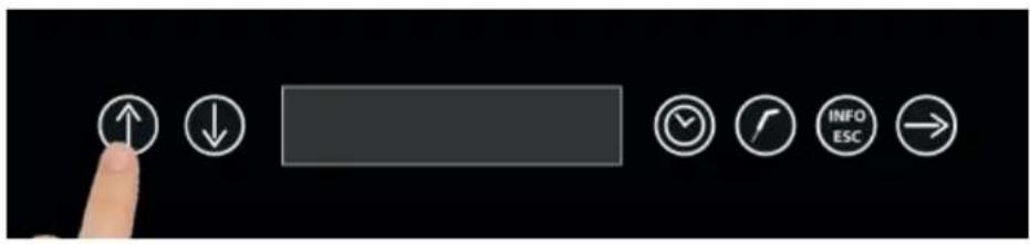
User interface toolbar with navigation buttons including up/down arrows, a blank input field, and function icons like checkmark, compass, info ESC, and right arrow.Set the temperature value with the UP and DOWN buttons
text_image
User interface toolbar with directional buttons and a finger pointing to the right buttonAfter pressing the CONFIRMATION button you will be requested to insert the food probe
natural_image
Close-up of a black soldering iron with a pointed tip (no text or symbols visible)Once you have inserted the food probe and after that the machinery has detected the actual insertion of the probe, the cycle will start and the display will show THAWING IN PROGRESS.
The cycle will end only when the temperature measured at the core will be equal to the pre-set value of +10°C. The cycle end is communicated with a buzzer that emits a sound and the time cycle button which flashes. By pressing this button, you can end the buzzer.
Once the cycle is finished, the machinery will start the PRESERVATION mode.
To be noticed that this phase can be maintained for a suggested maximum duration of 8 hours.

4.8 - DEFROSTING CYCLE
The defrosting cycle is essential to defrost the evaporator. The cycle has a duration of 600 seconds.
With the machinery in STOP mode :
text_image
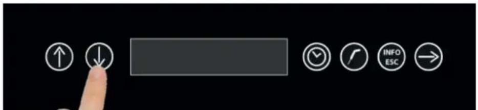
User interface toolbar with navigation and function icons including up/down arrows, checkmark, clock, refresh, info ESC, and returnPress the UP and DOWN buttons to select the cycle 6 DEFROSTING.
text_image
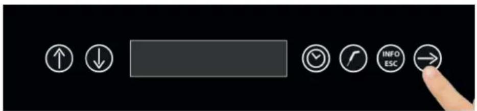
User interface toolbar with directional buttons and a finger pointing to the right buttonTo select this cycle, press the CONFIRMATION button
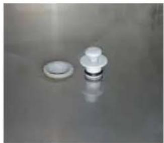
The cycle starts automatically with the countdown of the time remaining to finish, during the cycle the display will show DEFROSTING IN PROGRESS. Please note that at this stage it is advisable to remove the plug from the condensate water drain outlet on the cell surface (see image below).
natural_image
Close-up of a white plastic sink with a small circular component and a small plate, placed on a reflective surface (no text or symbols visible)
The cycle end is communicated with a buzzer that emits a sound and the time cycle button which flashes. By pressing this button, you can end the buzzer.
4.9 - EXPORT HACCP
The machinery has the feature of exporting the HACCP data.
Through the USB port on the control panel on the right of the CONFIRM button, you can export a text file (.txt) which corresponds to approximately one month of operation (120 hours of operation).
text_image
User interface toolbar with navigation and function icons including up/down, clock, timer, and navigation buttonsWith the machinery in STOP mode :
text_image
User interface toolbar with navigation and function icons including up/down arrows, checkmark, call, refresh, info, ESC, and right-pointing arrowPress the UP and DOWN buttons to select the cycle 7 EXPORT HACCP.
text_image
User interface buttons including up/down arrows, a blank rectangle, clock, refresh, info/ESC, and navigation arrowRemove the USB protection cap, insert an empty USB memory stick, without any previously stored data. Press the CONFIRMATION button to start the cycle.
At the end of the data download, the display will show the STOP writing and, as per a finished cycle, there will be a sound emitted by the buzzer. Press the time cycle button to end the buzzer.
The data are as follows :
S/N: 1234567890
31/03/2015 14:33
| Start | | | Stop | | | CYCLE | | P | | in [°C] | | out [°C] | | A | |
| 27/03/2015 | 10:11 | 27/03/2015 | 10:32 | AUTOMATIC BLAST CHILLING | 1 | +27.4 | | +3.0 | | 0 | |
| 27/03/2015 | 15:09 | 27/03/2015 | 15:22 | AUTOMATIC SHOCK FREEZING | 1 | +17.1 | | -18.0 | | 0 | |
| 31/03/2015 | 06:38 | 31/03/2015 | 06:42 | MANUAL BLAST CHILLING | 0 | +20.0 | | +3.0 | | 0 | |
| 31/03/2015 | 13:26 | 31/03/2015 | 14:22 | AUTOMATIC SHOCK FREEZING | 1 | +24.8 | | -18.0 | | 0 | |
Start : cycle start date and time
Stop : cycle end date and time
Cycle : type of cycle
P: food probe use (1 = temperature cycle; 0 = time cycle)
in [°C] : cycle starting temperature
out [°C] : cycle end temperature
A : identify if during the cycle some anomalous cell temperature alarm occurred (1= alarm recorder; 0 = no alarm dangerous for the food occurred )
4.10 - STERILIZATION (OPTIONAL)
Manual time cycle with a duration of 300 seconds.
With the machinery in STOP mode :
text_image
User interface toolbar with navigation and function buttons including up/down arrows, timer, clock, info/ESC, and right-pointing arrowPress the UP and DOWN buttons to select the cycle 8 STERILIZATION
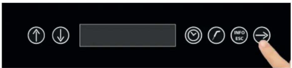
text_image
User interface toolbar with navigation and function icons including up/down, check, rotate, info ESC, and progress arrowTo select this cycle press the CONFIRMATION button.
The cycle starts automatically with the countdown of the time remaining to finish.
The cycle end is communicated with a buzzer that emits a sound and the time cycle button which flashes. By pressing this button, you can end the buzzer.

5 - MENU' INFO-ESC
The machinery has a second menu available which you can access by pressing the button

Once you have pressed that button, with the UP and DOWN buttons you can visualize the following menu:
1- I/O (also displayed during a cycle) read only
2- Active alarms (also displayed during a cycle) write only
| 3- | Language | read | and | |
| 4- | Time | read | and | |
| 5- | Alarms | list | only | |
| 6- | S/N | only | authorized | |
| 7- | Parameters | only | authorized | |
| 8- | Software | only | authorized | |
| 9- | Scanner | only | authorized | |
| 10- | Reset | only | authorized |
Some of the menu as shown in the description above, are accessible after entering the password.
The password is provided by the technical service to qualified technicians only because any changes, especially in the parameters section, radically alter the functioning of machinery. The read-only data are rather informative and those without password are setting for the end user.
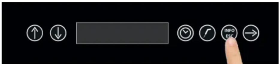
text_image
User interface toolbar with directional icons and a finger pointing to an 'INFO ESC' buttonWith the machinery in STOP mode, press the Info-ESC button

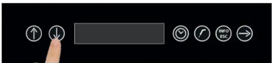
text_image
User interface toolbar with navigation and function icons including up/down arrows, checkmark, call, info, and ESCPressing the UP or DOWN buttons you can scroll the whole menu
5.1 - I/O
The I/O submenu, also displayed during a duty cycle, allows the display of the following information:
- Air probe temperature : value expressed in °C
- Evaporator probe temperature: value expressed in °C
- Condenser probe temperature: value expressed in °C
- Food probe temperature: value expressed in °C
- D1 Door micro switch 1 : With value 1 active, with value 0 not active
- D2 Magnetothermic : With value 1 active, with value 0 not active
- U1 Compressor: With value 1 active, with value 0 not active
- U2 Fans: With value 1 active, with value 0 not active
- U3 Door frame resistor: With value 1 active, with value 0 not active
- U4 Sterilizer/Led/Alarm: With value 1 active, with value 0 not active
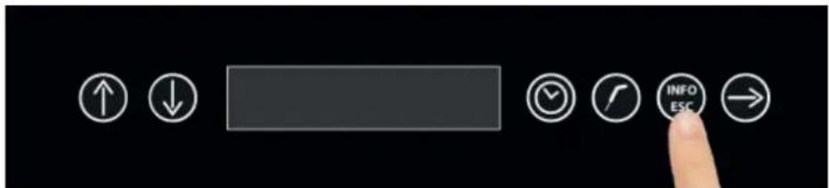
text_image
User interface toolbar with directional icons and a finger pointing to an 'INFO ESC' buttonWith the machinery in STOP mode, press the Info-ESC button
text_image
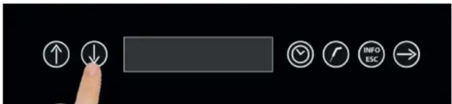
User interface toolbar with navigation and function buttons including up/down arrows, checkmark, call, refresh, info, ESC, and right-pointing arrowSelect the submenu 1 with the UP and DOWN buttons

text_image
User interface buttons including up/down arrows, a blank input field, checkmark, call, info/ESC, and navigation arrowPress the CONFIRMATION button
text_image
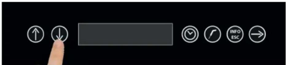
User interface toolbar with navigation and function icons including up/down arrows, checkmark, call, refresh, info, ESC, and right-pointing arrowScroll with the UP and DOWN buttons to display all the values
text_image
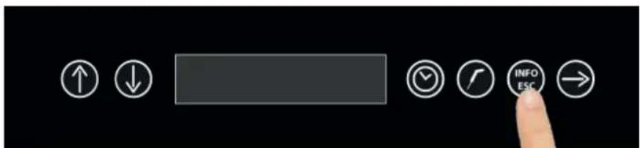
User interface buttons with directional icons and a finger pointing to the 'INFO ESC' buttonPress the INFO-ESC button to go back to STOP mode.
5.2 - ACTIVE ALARMS
The ACTIVE ALARMS submenu, also displayed during a cycle, allows to display a list of the alarms that are in progress during a cycle. If there are no alarms, the display will show NO ALARMS.
To be noted that the maintenance alarm, the food probe not inserted alarm and the preservation alarm are not available in this list.
text_image
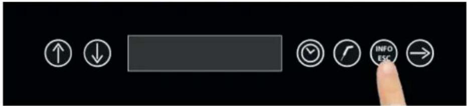
User interface toolbar with directional icons and a finger pointing to the 'INFO ESC' buttonWith the machinery in STOP mode, press the Info-ESC button
text_image
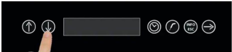
User interface buttons including up/down arrows, a blank input field, clock, refresh, info/ESC, and navigation arrowSelect the submenu 2 with the UP and DOWN buttons
text_image
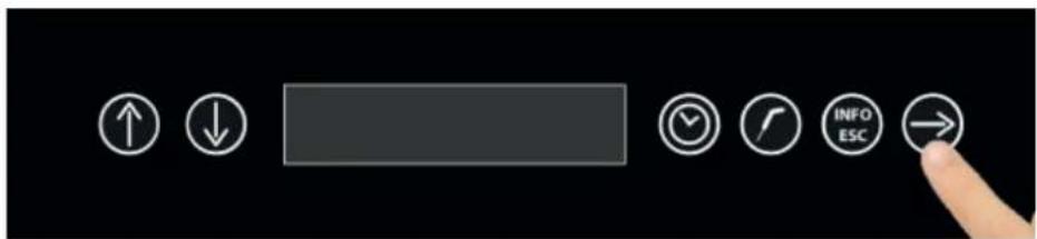
User interface toolbar with directional buttons and a finger pointing to the right buttonPress the CONFIRMATION button
text_image
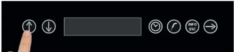
User interface toolbar with navigation and function icons including up/down, check, refresh, info ESC, and returnScroll with the UP and DOWN buttons to display all the alarms
text_image
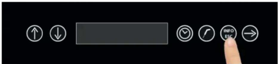
User interface toolbar with directional icons and a finger pointing to the button labeled 'INFO ESC'Press the INFO-ESC button to go back to STOP mode.
5.3 - LANGUAGE
The LANGUAGE submenu, allows the user to set the menu language. Depending on the installed firmware, the available languages are the following:
FW 1) ITALIAN - ENGLISH - FRENCH - SPANISH - GERMAN
FW 2) ITALIAN - CZECH - DUTCH - POLISH - SWEDISH
Once you have selected the language, the buzzer will emit a sound and the display will show the STOP writing.
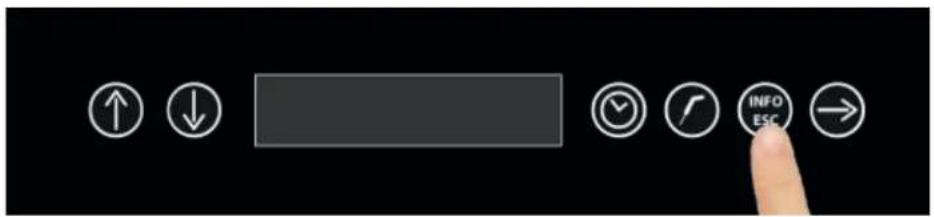
text_image
User interface toolbar with directional icons and a finger pointing to an 'INFO ESC' buttonWith the machinery in STOP mode, press the Info-ESC button
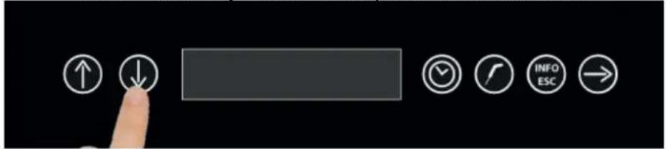
text_image
User interface toolbar with navigation and function icons including up/down arrows, checkmark, refresh, info ESC, and returnSelect the submenu 3 with the UP and DOWN buttons
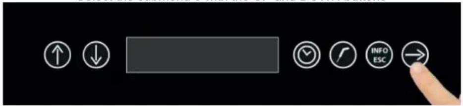
text_image
User interface toolbar with directional buttons and a finger pointing to the right buttonPress the CONFIRMATION button
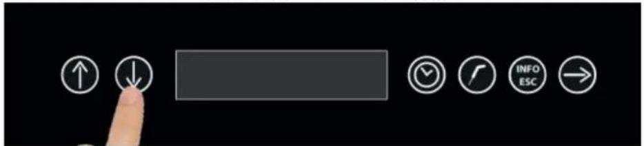
text_image
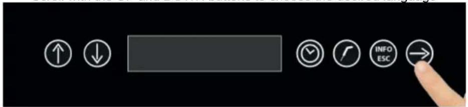
User interface toolbar with navigation and function icons including up/down arrows, checkmark, refresh, info, and ESCScroll with the UP and DOWN buttons to choose the desired language
text_image
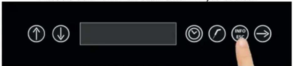
User interface toolbar with directional buttons including up/down arrows, navigation bar, clock, refresh, info ESC, and finger pointing to the right button.Press the CONFIRMATION button to confirm your selection
text_image
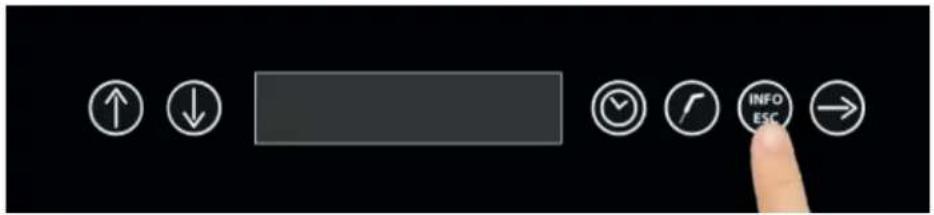
User interface toolbar with navigation and function icons including up/down arrows, a blank bar, clock, refresh, info/ESC buttons, and a finger pointing to the right button.After emitting a sound to confirm your choice, the display will show the STOP writing.
The TIME submenu, allows the user to set the date and system clock. To be noted that these setting are crucial as they are reported in the HACCP reports
The date has the format DD-MM-YY
The time has the format HH: MM
text_image
User interface toolbar with directional icons and a finger pointing to an 'INFO ESC' buttonWith the machinery in STOP mode, press the Info-ESC button
text_image
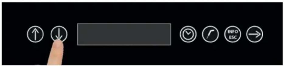
User interface toolbar with navigation and function icons including up/down arrows, checkmark, call, refresh, info, and ESCSelect the submenu 4 with the UP and DOWN buttons
text_image
User interface toolbar with directional buttons and a finger pointing to the right buttonPress the CONFIRMATION button
text_image
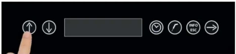
User interface toolbar with navigation and function buttons including up/down, progress bar, checkmark, refresh, info ESC, and returnScroll with the UP and DOWN buttons to set the correct value. To pass on the following datum press the CONFIRMATION button
text_image
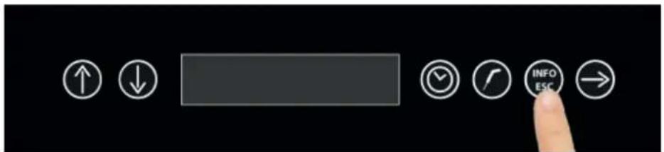
User interface toolbar with directional icons and a finger pointing to an 'INFO ESC' buttonPress the INFO-ESC button to go back to STOP mode

5.5 - ALARMS LIST
The ALARMS LIST submenu allows to display in sequence the last 32 alarms occurred with date and start time. To be noted that the maintenance alarm, the food probe not inserted alarm and the preservation alarm are not available in this list.
text_image
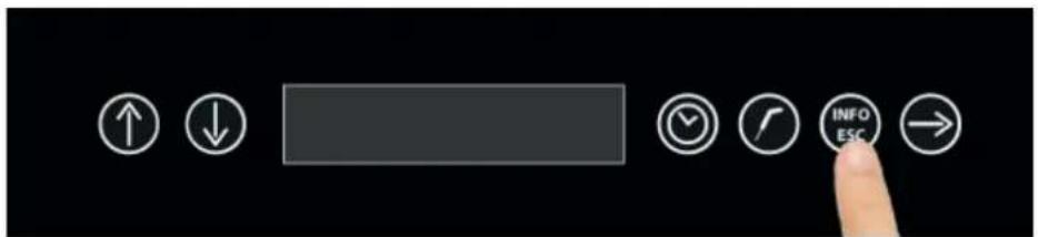
User interface toolbar with directional buttons and a finger pointing to an 'INFO ESC' buttonWith the machinery in STOP mode, press the Info-ESC button
text_image
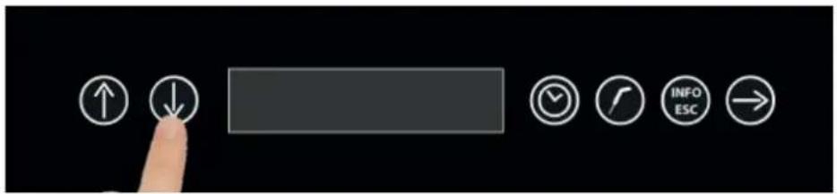
User interface toolbar with navigation and function icons including up/down arrows, checkmark, call, refresh, info, and ESCSelect the submenu 5 with the UP and DOWN buttons
text_image
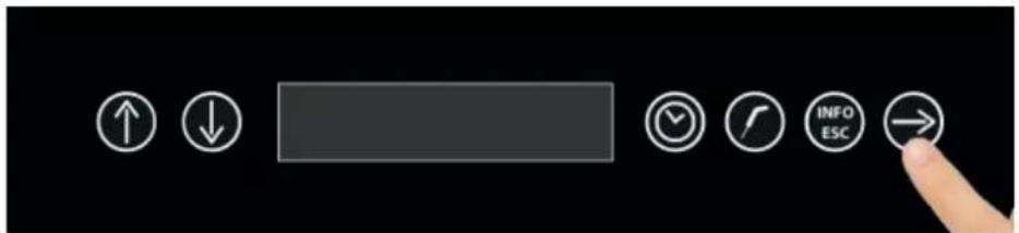
User interface toolbar with navigation and function buttons including up/down, progress bar, checkmark, refresh, info ESC, and right-pointing handPress the CONFIRMATION button If any alarm is recorded, than the display will start from number 01
text_image
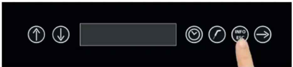
User interface toolbar with directional icons and a finger pointing to an 'INFO ESC' buttonPress the INFO-ESC button to go back to STOP mode

Troubleshooting
E Z
6- ALARMS CHART
In case there is a malfunction, the machinery warns the user with a buzzer sound which can be muted by pressing the INFO / ESC key.
The alarm state continues until the cause of the alarm is removed.
Below is the chart with the expected alarms in case of malfunction of the machinery:
| ERROR MESSAGE DESCRIPTION | TION POSSIBLE ROOT CAUSE USER SOLUTION | ||
| PRESERVATION IN PRO-GRESS | Warning that the preservation cycle is in progress, maximum suggested duration 8 hours | Cycle completed correctly | Remove the food from the blast chiller and stop the cycle |
| FOOD PROBE NOT INSERT | The food probe is not inserted | Probe not inserted or malfunctioning. | Insert the food probe. If the problem persists, contact a qualified technician. |
| DOOR OPEN | The door has been left open Door open | Close the door. If the problem persists, contact a qualified technician. | |
| HIGH CONDENSER | Not enough heat dissipation at the condenser | High room temperature, high condenser temperature, condenser fan not working | Ventilate the room, clean the condenser and do not block the air vents. If the problem persists, contact a qualified technician. |
| BLACKOUT | Failure of the power supply during one cycle | Failure of the power supply during one cycle | Restore the machinery power supply |
| MAGNETOTHERMIC | Opening of the magnetothermic switch contact | Failure or overload of the compressor | Contact a qualified technician |
| AIR PROBE | Malfunction or breakdown of the air probe | Malfunction or breakdown of the air probe | Contact a qualified technician |
| EVAPORATOR PROBE | Malfunction or breakdown of the evaporator probe | Malfunction or breakdown of the evaporator probe Contact a qualified technician | Contact a qualified technician |
| CONDENSER PROBE | Malfunction or breakdown of the condenser probe | Malfunction or breakdown of the condenser probe | Contact a qualified technician |
| FOOD PROBE | Malfunction or breakdown of the food probe | Malfunction or breakdown of the food probe | Contact a qualified technician |
| NOT USB | During the HACCP data download, the USB memory stick was not plugged in | USB memory stick not plugged in, not functioning or not detected | Plug in the USB memory stick. If the problem persists, contact a qualified technician. |
| NO DATA | HACCP data not available | No cyle has been performed or the data have been erased | Operate the machinery in order to have the HACCP available |
| ERROR MESSAGE DESCRIPTION | TION POSSIBLE ROOT CAUSE | USER SOLUTION | |
| HIGH TEMPERATURE | HACCP alarm: air temperature in the cell is higher that the set limits | Refrigerant gas leak. Faulty reading of probes, condenser fan blocked, compressor in block | Shutdown the machinery, turn it on again. If the problem persists, contact a qualifi ed technician. |
| LOW TEMPERATURE | HACCP alarm: air temperature in the cell is lower that the set limits | Frozen evaporator, the compres-sor works continuously, the com-pressor relay contact is broken, faulty reading of probes. | Shutdown the machinery, turn it on again and eventually perform a defrosting cycle. If the problem per-sists, contact a qualifi ed technician. |
When calling for a qualified technician, it is mandatory to provide the following informations:
Error message
Serial number of the machinery
To delete an alarm, place the machinery in STAND-BY mode

1.1 - ANALYSES DES RISQUES
Liste des dangers :
natural_image
Simple line drawing of a trash bin with two crossed lines indicating no waste or prohibition (no text or symbols)
IT08020000000615
text_image
User interface toolbar with navigation and function icons including up/down, clock, refresh, info ESC, and battery7- Exportation HACCP
natural_image
Close-up of a black soldering iron with a pointed tip (no text or symbols visible)
natural_image
Steamed flat pan with red meat and garnish, heart-shaped decoration on slice (no text or symbols)
4 - CYCLES DE FONCTIONNEMENT
7- Exportation HACCP
text_image
User interface toolbar with directional icons and a finger pointing to the right buttontext_image
User interface toolbar with directional buttons and a finger pointing to the right button
4.3 - CYCLE DE REFROIDISSEMENT AUTOMATIQUE
text_image
User interface toolbar with navigation and function icons including up/down arrows, checkmark, refresh, info ESC, and returntext_image
User interface toolbar with directional buttons and a finger pointing to the buttontext_image
User interface toolbar with directional buttons and a finger pointing to the right button labeled 'INFO ESC'natural_image
Close-up of a black soldering iron with a pointed tip (no text or symbols visible)text_image
User interface toolbar with navigation and function icons including up/down arrows, checkmark, refresh, info ESC, and returntext_image
User interface buttons with directional icons and a finger pointing to a button labeled 'INFO ESC'text_image
User interface toolbar with directional buttons and a finger pointing to the right buttontext_image
User interface toolbar with navigation and function icons including up/down, progress bar, checkmark, refresh, info ESC, and returntext_image
User interface toolbar with directional icons and a finger pointing to the right buttontext_image
User interface toolbar with navigation and function icons including up/down arrows, checkmark, call, info, ESC, and right-pointing arrowtext_image
User interface toolbar with directional icons including up/down arrows, timer, refresh, and navigation buttonsLa pression de la touche CONFIRMER lance le cycle.
text_image
User interface toolbar with navigation and function icons including up/down arrows, checkmark, refresh, info escape, and returntext_image
User interface toolbar with directional icons and a finger pointing to a button labeled 'INFO ESC'text_image
User interface toolbar with directional buttons and a finger pointing to the right buttontext_image
User interface toolbar with navigation and function buttons including up/down, down arrow, progress bar, clock, refresh, info ESC, and returntext_image
User interface toolbar with directional buttons and a finger pointing to the right buttontext_image
User interface toolbar with navigation and function icons including up/down arrows, a blank button, clock, refresh, info ESC, and returntext_image
User interface toolbar with directional icons and a finger pointing to the right buttonnatural_image
Close-up of a black soldering iron with a pointed tip (no text or symbols visible)text_image
User interface toolbar with navigation and function icons including up/down arrows, checkmark, refresh, info escape, and returntext_image
User interface toolbar with directional buttons and a finger pointing to the right buttontext_image
User interface toolbar with navigation and function icons including up/down, down arrow, progress bar, clock, refresh, info ESC, and finger pointing to right buttonnatural_image
Close-up of a black soldering iron with a pointed tip (no text or symbols visible)text_image
User interface toolbar with navigation and function icons including up/down arrows, checkmark, refresh, info, and ESCtext_image
User interface toolbar with directional buttons and a finger pointing to a button labeled 'INFO ESC'text_image
User interface toolbar with directional buttons and a finger pointing to the right buttontext_image
User interface toolbar with navigation and function icons including up/down arrows, checkmark, call, refresh, info, ESC, and right-pointing arrowtext_image
User interface toolbar with directional buttons and a finger pointing to the right buttontext_image
User interface toolbar with navigation and function icons including up/down, check, rotate, info ESC, and returntext_image
User interface toolbar with navigation and function icons including up/down, check, call, info, ESC, and finger pointing to the right button.La pression de la touche CONFIRMER lance le cycle.
text_image
User interface toolbar with navigation and function icons including up/down arrows, checkmark, clock, info/ESC, and right-pointing arrowtext_image
User interface toolbar with navigation and function buttons including up/down, progress bar, clock, call, info/ESC, and right-pointing arrowtext_image
User interface toolbar with directional buttons and a finger pointing to the right buttontext_image
User interface toolbar with navigation and function icons including up/down arrows, checkmark, refresh, info/ESC, and return buttontext_image
User interface toolbar with directional buttons and a finger pointing to the right buttontext_image
User interface toolbar with navigation buttons and a finger pointing to an up/down arrow icontext_image
User interface buttons including up/down arrows, a blank input field, clock, checkmark, info/ESC, and navigation arrownatural_image
Close-up of a black soldering iron with a pointed tip (no text or symbols visible)text_image
User interface buttons including up/down arrows, a blank input field, clock, refresh, info/ESC, and navigation arrowtext_image
User interface toolbar with directional buttons and a finger pointing at a button labeled 'INFO ESC'text_image
User interface toolbar with directional buttons and a finger pointing to the right buttontext_image
User interface toolbar with navigation and function icons including up/down arrows, checkmark, clock, refresh, info ESC, and returntext_image
User interface toolbar with directional buttons and a finger pointing to the right buttontext_image
User interface toolbar with navigation buttons including up/down, zoom, refresh, and directional iconstext_image
User interface toolbar with directional icons and a finger pointing to the right buttonLa pression de la touche CONFIRMER lance le cycle.
text_image
User interface toolbar with navigation and function icons including up/down arrows, checkmark, call, refresh, info, and ESCtext_image
User interface toolbar with navigation and function buttons including up/down, progress bar, clock, call, info/ESC, and right-pointing arrowtext_image
User interface toolbar with directional buttons and a finger pointing to the right buttontext_image
User interface toolbar with navigation and function icons including up/down arrows, checkmark, refresh, info, and ESCtext_image
User interface toolbar with directional buttons and a finger pointing to the right buttontext_image
User interface toolbar with navigation and function icons including up/down arrow, progress bar, checkmark, refresh, info ESC, and right-pointing arrowtext_image
User interface toolbar with directional buttons and a finger pointing to the right buttonnatural_image
Close-up of a black soldering iron with a pointed tip (no text or symbols visible)text_image
User interface toolbar with directional icons and a finger pointing to a buttontext_image
User interface toolbar with directional buttons and a finger pointing to the buttonnatural_image
Close-up of a white plastic floor drain with a small circular component and a small stopper (no text or symbols visible)text_image
User interface toolbar with navigation and function icons including up/down, clock, timer, and navigation buttonstext_image
User interface toolbar with navigation and function icons including up/down arrows, checkmark, call, refresh, info, ESC, and right-pointing arrowtext_image
User interface toolbar with directional icons and a finger pointing to the right buttontext_image
User interface toolbar with navigation and function buttons including up/down arrows, timer, clock, info/ESC, and right-pointing arrowtext_image
User interface toolbar with directional buttons and a finger pointing to the buttontext_image
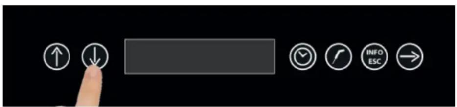
User interface toolbar with directional icons and a finger pointing to an 'INFO ESC' buttonQuand l'écran affi che le message STOP, presser la touche Info-ESC
text_image
User interface toolbar with navigation and function icons including up/down arrows, timer, clock, refresh, info ESC, and right-pointing arrowtext_image
User interface toolbar with navigation and function icons including up/down, check, call, info, and ESCQuand l'écran affi che le message STOP, presser la touche Info-ESC
text_image
User interface toolbar with navigation and function icons including up/down arrows, checkmark, call, refresh, info, ESC, and right-pointing arrowtext_image
User interface toolbar with directional buttons and a finger pointing to the right buttonPresser la touche confirmer.
text_image
User interface toolbar with navigation and function icons including up/down arrows, checkmark, refresh, info/ESC, and return buttontext_image
User interface toolbar with directional icons and a finger pointing to an 'INFO ESC' buttontext_image
User interface toolbar with directional icons and a finger pointing to an 'INFO ESC' buttonQuand l'écran affi che le message STOP, presser la touche Info-ESC
text_image
User interface toolbar with navigation and function icons including up/down arrows, checkmark, refresh, info, and ESCtext_image
User interface toolbar with directional buttons and a finger pointing to the right button labeled 'INFO ESC'Presser la touche confi rmer.
text_image
User interface toolbar with navigation and function buttons including up/down, down arrow, progress bar, clock, refresh, info ESC, and returntext_image
User interface toolbar with directional buttons and a finger pointing to an 'INFO ESC' buttontext_image
User interface toolbar with directional icons and a finger pointing to an 'INFO ESC' buttonQuand l'écran affi che le message STOP, presser la touche Info-ESC
text_image
User interface toolbar with navigation and function icons including up/down arrows, checkmark, checkmark, info ESC, and right-pointing arrowtext_image
User interface toolbar with directional buttons and a finger pointing to the right buttonPresser la touche confirmer.
text_image
User interface toolbar with navigation and function icons including up/down arrows, checkmark, checkmark, info ESC, and returntext_image
User interface toolbar with directional icons and a finger pointing to the right buttontext_image
User interface toolbar with directional buttons and a finger pointing to an 'INFO ESC' buttontext_image
User interface toolbar with directional icons and a finger pointing to an 'INFO ESC' buttonQuand l'écran affi che le message STOP, presser la touche Info-ESC
text_image
User interface toolbar with navigation and function icons including up/down arrows, checkmark, call, refresh, info, ESC, and right-pointing arrowtext_image
User interface toolbar with directional buttons and a finger pointing to the right buttonPresser la touche confirmer.
text_image
User interface toolbar with navigation and function buttons including up/down, progress bar, checkmark, refresh, info ESC, and returntext_image
User interface toolbar with directional icons and a finger pointing to an 'INFO ESC' buttontext_image
User interface toolbar with directional icons and a finger pointing to an 'INFO ESC' buttonQuand l'écran affi che le message STOP, presser la touche Info-ESC
text_image
User interface toolbar with navigation and function icons including up/down arrows, checkmark, call, refresh, info, ESC, and right-pointing arrowtext_image
User interface toolbar with directional buttons and a finger pointing to the right buttonPresser la touche confirmer.
text_image
User interface toolbar with directional icons and a finger pointing to an 'INFO ESC' buttonnatural_image
Symbol of a trash bin crossed out by two diagonal lines (no text or numbers present)
IT08020000000615
natural_image
Close-up of a black soldering iron with a pointed tip (no text or symbols visible)
natural_image
Steamed flat pan with heart-shaped decoration on a dark surface (no text or symbols visible)
text_image
User interface toolbar with directional icons and a finger pointing to the right buttontext_image
User interface toolbar with directional icons and a finger pointing to the right button
text_image
User interface toolbar with navigation and function icons including up/down arrows, checkmark, refresh, info ESC, and returntext_image
User interface toolbar with directional icons and a finger pointing to the right buttontext_image
User interface toolbar with directional buttons and a finger pointing to the right buttonnatural_image
Close-up of a black soldering iron with a pointed tip (no text or symbols visible)
text_image
User interface toolbar with navigation and function icons including up/down arrows, checkmark, clock, refresh, info ESC, and returntext_image
User interface toolbar with directional buttons and a finger pointing at a button labeled 'INFO ESC'text_image
User interface toolbar with directional buttons and a finger pointing to the right buttontext_image
User interface toolbar with navigation and function icons including up/down, progress bar, clock, refresh, info ESC, and returntext_image
User interface toolbar with directional icons and a finger pointing to the right buttontext_image
User interface buttons including up/down arrows, a blank input field, clock, refresh, info/ESC, and navigation arrowtext_image
User interface toolbar with directional icons including up/down arrows, progress bar, clock, refresh, info ESC, and navigation arrowtext_image
User interface toolbar with navigation and function icons including up/down arrows, checkmark, call, refresh, info, and ESC buttonstext_image
User interface toolbar with directional icons and a finger pointing to a button labeled 'INFO ESC'text_image
User interface toolbar with directional buttons and a finger pointing to the right buttontext_image
User interface toolbar with navigation and function buttons including up/down arrow, progress bar, clock, refresh, info ESC, and return buttontext_image
User interface toolbar with directional icons and a finger pointing to the right buttontext_image
User interface toolbar with navigation and function buttons including up/down, check, call, refresh, info, ESC, and return iconstext_image
User interface toolbar with directional icons and a finger pointing to the right buttonnatural_image
Close-up of a black soldering iron with a pointed tip (no text or symbols visible)text_image
User interface toolbar with navigation and function icons including up/down arrows, checkmark, refresh, info escape, and returntext_image
User interface toolbar with directional icons and a finger pointing to the right buttontext_image
User interface toolbar with navigation and function icons including up/down, check, clock, refresh, info ESC, and right-pointing handnatural_image
Close-up of a black pen or stylus with a pointed tip, isolated on white background (no text or symbols)