DDR040EB2WDB - Dehumidifier DANBY - Free user manual and instructions
Find the device manual for free DDR040EB2WDB DANBY in PDF.

| Brand | Danby |
| Model | DDR040EB2WDB |
| Product Type | Dehumidifier |
| Refrigerant | R32 (flammable) |
| Extraction Capacity | 40 pints (18.9 L) per day |
| Power Supply | 115 V ~ 60 Hz |
| Operating Temperature Range | 5°C to 32°C |
| Operating Humidity Range | 30% to 90% RH |
| Humidity Setting | 35% to 80% RH (in 5% increments) |
| Display | Digital display with ±5% RH accuracy |
| Fan Speed | Low and High |
| Timer | Programmable timer (0.5 to 24 hours) with auto start and stop |
| Continuous Mode | Yes (displays "CO") |
| Water Drainage | Water bucket (5.7 L) and continuous gravity drainage |
| Full Bucket Indicator | Yes (automatic compressor shut-off) |
| Air Filter | Washable and reusable (clean every 250 hours) |
| Defrost Function | Automatic |
| Casters | Yes (4 casters included) |
| Error Codes | EH (humidity sensor), E1/E2 (temperature sensor), E3 (gas leak) |
| Warranty | 2 years (functional parts) |
Frequently Asked Questions - DDR040EB2WDB DANBY
User questions about DDR040EB2WDB DANBY
0 question about this device. Answer the ones you know or ask your own.
Ask a new question about this device
Download the instructions for your Dehumidifier in PDF format for free! Find your manual DDR040EB2WDB - DANBY and take your electronic device back in hand. On this page are published all the documents necessary for the use of your device. DDR040EB2WDB by DANBY.
USER MANUAL DDR040EB2WDB DANBY
Owner's Manual....1 - 8
DÉSHUMIDIFICATEUR
Danby Products Limited, Guelph, Ontario, Canada N1H 6Z9
Danby Products Inc. Findlay, Ohio, U.S.A. 45840
www.danby.com

Printed in China | Imprimé en Chine | Impreso en China
2024.03.18
Welcome
Welcome to the Danby family. We are proud of our quality products and we believe in dependable service. We suggest that you read this owner's manual before plugging in your new appliance as it contains important operation information, safety information, troubleshooting and maintenance tips to ensure the reliability and longevity of your appliance.
Visit www.Danby.com to access self service tools, FAQs and much more. For additional assistance call 1-800-263-2629.
Note the information below; you will need this information to obtain service under warranty.
You must provide the original purchase receipt to validate your warranty and receive service.
Model Number: ____
Serial Number: ____
Date of Purchase: ____
Need Help?
Before you call for service, here are a few things you can do to help us serve you better.
Read this owner's manual:
It contains instructions to help you use and maintain your appliance properly.
If you receive a damaged appliance:
Immediately contact the retailer or builder that sold you the appliance.
Save time and money:
Check the troubleshooting section at the end of this manual before calling. This section will help you solve common problems that may occur.

natural_image
Simple black-and-white icon of a telephone handset inside a circle (no text or symbols)1-800-26- Danby
(1-800-263-2629)
| Important Note: Read this manual carefully before installing or operating this appliance. Make sure to save the manual for future reference. | ||
 | CAUTION S | Shows that the operation manual should be read carefully. |
 | CAUTION S | Shows that service personnel should be handling this equipment with reference to the installation manual. |
 | CAUTION S | Shows that the information is available such as the operating manual or the installation manual. |
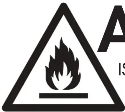
A2L
ISO 817
CAUTION: RISK OF FIRE FLAMMABLE MATERIALS
WARNING:
- This appliance is not intended for use by persons (including children) with reduced physical, sensory or mental capabilities or lack of experience and knowledge, unless they have been given supervision or instruction concerning use of the appliance by a person responsible for their safety.
• Children should be supervised to ensure that they do not play with the appliance.
- Care should be taken when using the appliance in a room with the following persons: infants, children, elderly people, and people not sensitive to humidity.
- Servicing shall only be performed as recommended by the equipment manufacturer. Maintenance and repair requiring the assistance of other skilled personnel shall be carried out under the supervision of a person competent in the use of flammable refrigerants. You should never try to take apart or repair the appliance by yourself.
- DO NOT modify the length of the power cord or use an extension cord to power the appliance.
- If the power supply cord is damaged, it must be replaced by the manufacturer, its service agent or similarly qualified persons in order to avoid a hazard. Do not operate the appliance with a damaged cord or plug. Discard the appliance or return it to an authorized service facility for examination and/or repair.
- DO NOT share a single outlet with other electrical appliances. Improper power supply can cause fire or electrical shock.
- Do not run the power cord under carpeting. Do not cover the power cord with throw rugs, runners, or similar coverings. Do not route the power cord under furniture or appliances. Arrange the power cord away from high traffic areas and where it will not be tripped over. Do not place heavy objects on the power cord and take care that the cord is not compressed.
- In a thunderstorm, the power must be cut to avoid damage to the appliance due to lightning.
- Do not insert or pull out the power cord with wet hands.
- Prior to cleaning or other maintenance, the appliance must be disconnected from the power supply.
- Disconnect the power if strange sounds, smells, or smoke comes from the appliance.
- The rating plate is located on the rear or side of the appliance and contains electrical and other technical data specific to this appliance. Do not exceed the rating of the power outlet or connection device.
- Flammable refrigerant R32 is used within this appliance.
- When maintaining or disposing the appliance, the refrigerant (R32) shall be recovered properly and shall not discharge to the air directly.
• Compliance with national gas regulations shall be observed.
- Any person who is involved with working on or breaking into a refrigerant circuit should hold a current valid certification from an industry-accredited assessment authority, which authorises their competence to handle refrigerants safely in accordance with an industry recognised assessment specification.
- Examples for such working procedures are: breaking into the refrigerant circuit, opening of sealed components, opening of ventilated enclosures.
- No open fire or device like switch that may generate a spark or arcing shall being near the appliance to avoid causing ignition of the flammable refrigerant used. Please follow the instructions carefully to store or maintain the appliance to prevent mechanical damage from occurring.
WARNING:
- The appliance shall be stored in a room without continuously operating ignition sources such as open flames or a operating gas heater, or ignition sources such as an operating electric heater close to the appliance. Do not place the appliance near a heat source.
- Do not install the appliance in a location that may be exposed to combustible gas. If combustible gas accumulates around the unit, it may cause fire. Do not use the unit near flammable gas or combustibles, such as gasoline, benzene, thinner, etc.
- Do not pierce or burn the refrigerant circuit. Be aware that refrigerants may not contain an odour.
- Do not use means to accelerate the defrosting process or to clean the appliance other than those recommended by the manufacturer.
- Keep ventilation openings clear of obstruction. Do not cover the intake or exhaust openings with cloths or towels.
- The appliance shall be stored so as to prevent mechanical damage from occurring.
- The appliance shall be stored in a well-ventilated area where the room size corresponds to the room area as specified for operation.
- Turn off the appliance when not in use.
- Do not drink or use the water drained from the appliance.
- Do not take the water bucket out during operation.
- Place the appliance on a level, sturdy floor.
- Never insert your finger or other foreign objects into grills or openings. Take special care to warn children of these dangers.
- Do not climb up on or sit on the unit.
• Always insert the filters securely. Clean filter once every two weeks. - If water enters the unit, turn the unit off and disconnect the power, contact a qualified service technician.
- Do not place flower vases or other water container on top of the unit.
- If the appliance is knocked over during use, turn off the unit and unplug it from the main power supply immediately. Visually inspect the unit to ensure there is no damage. If you suspect the unit has been damaged, contact a technician or customer service for assistance.
- To reduce the risk of fire or electric shock, do not use this appliance with any solid-state speed control device.
- The appliance shall be installed in accordance with national wiring regulations.
- Be sure the appliance is properly grounded. To minimize shock and fire hazards, proper grounding is important. The power cord is equipped with a three-prong grounding plug for protection against shock hazards. Your unit must be used in a properly grounded wall receptacle. If the wall receptacle you intend to use is not adequately grounded or protected by a time delay fuse or circuit breaker, have a qualified electrician install the proper receptacle. Please refer to the nameplate for the electrical data.
- Do not operate the appliance in a wet room such as a bathroom or laundry room. Do not operate in places where water may splash onto the appliance.
-
The circuit board (PCB) is designed with a fuse to provide overcurrent protection. Specifications of the fuse are printed on the circuit board, such as: T 3.15A/250V (or 350V), etc.
-
Transport of equipment containing flammable refrigerants: See transport regulations.
-
Marking of equipment using signs: See local regulations.
-
Disposal of equipment using flammable refrigerants: See national regulations.
-
Storage of equipment / appliances: The storage of equipment should be in accordance with the manufacturer's instructions.
-
Storage of packed (unsold) equipment: Storage package protection should be constructed such that the mechanical damage to the equipment inside the package will not cause a leak of the refrigerant charge. The maximum number of pieces of equipment permitted to be stored together will be determined by local regulations.
6. Information on servicing
1) Checks to the area: Prior to beginning work on systems containing flammable refrigerants, safety checks are necessary to ensure that the risk of ignition is minimized. For repair to the refrigerating system, the following precautions shall be complied with prior to conducting work on the system.
2) Work procedure: Work shall be undertaken under a controlled procedure so as to minimize the risk of a flammable gas or vapour being present while the work is being performed.
3) General work area: All maintenance staff and others working in the local area shall be instructed on the nature of work being carried out. Work in confined spaces shall be avoided. The area around the work space shall be sectioned off. Ensure that the conditions within the work area have been made safe by removing all flammable material.
4) Checking for the presence of refrigerant: The area shall be checked with an appropriate refrigerant detector prior to and during work to ensure the technician is aware of potentially flammable atmospheres. Ensure that the leak detection equipment being used is suitable for use with flammable refrigerants, i.e. non-sparking, adequately sealed or intrinsically safe.
5) Presence of fire extinguisher: If any hot work is to be conducted on the refrigeration equipment or any associated parts, appropriate fire extinguishing equipment shall be available to hand. Have a dry powder or CO_2 fire extinguisher adjacent to the work area.
6) No ignition sources: No person carrying out work in relation to a refrigeration system which involves exposing any pipe work that contains or has contained flammable refrigerant shall use any sources of ignition in such a manner that it may lead to risk of fire or explosion. All possible ignition sources including cigarette smoking, should be kept sufficiently far away from the site of installation, repairing, removing and disposal during which flammable refrigerant can possibly be released to the surrounding space. Prior to work taking place, the area around the equipment is to be surveyed to make sure there are no flammable hazards or ignition risks. No smoking signs shall be displayed.
7) Ventilated area: Ensure that the area is in the open or that it is adequately ventilated before breaking into the system or conducting any hot work. A degree of ventilation shall continue during the period that the work is carried out. The ventilation should safely disperse any released refrigerant and expel it externally into the atmosphere.
8) Checks to the refrigeration equipment: Where electrical components are being changed, they shall be fit for the purpose and to the correct specification. At all times the manufacturer's maintenance and service guidelines shall be followed. If in doubt, consult the manufacturer's technical department for assistance. The following checks shall be applied to installations using flammable refrigerants:
- The actual refrigerant charge size is in accordance with the room size within which the refrigerant containing parts are installed.
- The ventilation machinery and outlets are operating adequately and are not obstructed.
- If an indirect refrigerating circuit is being used, the secondary circuit shall be checked for the presence of refrigerant.
- Markings on the equipment continues to be visible and legible. Markings and signs that become illegible must be corrected.
- Refrigeration pipe or components are installed in a position where they are unlikely to be exposed to any substance which may corrode refrigerant containing components, unless the components are constructed of materials which are inherently resistant to being corroded or are suitable protected against being corroded.
9) Checks to electrical devices: Repair and maintenance to electrical components shall include initial safety checks and component inspection procedures. If a fault exists that could compromise safety, then no electrical supply shall be connected to the circuit until it is satisfactorily dealt with. If the fault cannot be corrected immediately but it is necessary to continue operation, an adequate temporary solution shall be used. This shall be reported to the owner of the equipment so all parties are advised. Initial safety checks shall include:
- That capacitors are discharged. This shall be done in a safe manner to avoid possibility of sparking.
- That no live electrical components and wiring are exposed while charging, recovering or purging the system.
- That there is continuity of earth bonding.
7. Repairs to sealed components
1) During repairs to sealed components, all electrical supplies shall be disconnected from the equipment being worked upon prior to any removal of sealed covers, etc. If it is absolutely necessary to have an electrical supply to equipment during servicing then a permanently operating form of leak detection shall be located at the most critical point to warn of a potentially hazardous situation.
2) Particular attention shall be paid to the following to ensure that by working on electrical components, the casing is not altered in such a way that the level of protection is affected. This shall include:
- Damage to cables, excessive number of connections, terminals not made to original specification, damage to seals, incorrect fitting of glands, etc.
- Ensure the apparatus is mounted securely.
- Ensure that seals or sealing materials have not degraded such that they no longer serve the purpose of preventing the ingress of flammable atmospheres. Replacement parts shall be in accordance with the manufacturer's specifications.
Note: The use of silicon sealant may inhibit the effectiveness of some types of leak detection equipment. Intrinsically safe components do not have to be isolated prior to working on them.
8. Repair to intrinsically safe components
Do not apply any permanent inductive or capacitance loads to the circuit without ensuring that this will not exceed the permissible voltage and current permitted for the equipment in use. Intrinsically safe components are the only types that can be worked on while live in the presence of a flammable atmosphere. The test apparatus shall be at the correct rating. Replace components only with parts specified by the manufacturer. Other parts may result in the ignition of refrigerant in the atmosphere from a leak.
9. Cabling
Check that cabling will not be subject to wear, corrosion, excessive pressure, vibration, sharp edges or any other adverse environmental effects. The check shall also take into account the effects of aging or continual vibration from sources such as compressors or fans.
10. Detection of flammable refrigerants
Under no circumstances shall potential sources of ignition be used in the searching for or detection of refrigerant leaks. A halide torch or any other detector using a naked flame shall not be used. The following leak detection methods are deemed acceptable for systems containing flammable refrigerants:
- Electronic leak detectors shall be used to detect flammable refrigerants but the sensitivity may not be adequate or may need recalibration. Detection equipment shall be calibrated in a refrigerant-free area. Ensure that the detector is not a potential source of ignition and is suitable for the refrigerant used.
- Leak detection equipment shall be set at a percentage of the LFL of the refrigerant and shall be calibrated to the refrigerant employed and the appropriate percentage of gas (25% maximum) is confirmed.
- Leak detection fluids are suitable for use with most refrigerants but the use of detergents containing chlorine shall be avoided as the chlorine may react with the refrigerant and corrode the copper or pipe-work.
- If a leak is suspected, all naked flames shall be removed or extinguished.
- If a leakage of refrigerant is found which requires brazing, all of the refrigerant shall be recovered from the system or isolated by means of shut off valves in a part of the system remote from the leak. Removal and evacuation shall be in according to the removal and evacuation section.
11. Removal and evacuation
When breaking into the refrigerant circuit to make repairs or for any other purpose conventional procedures shall be used. However, it is important that the best practice is followed since flammability is a consideration. The following procedures shall be adhered to:
• purge the circuit with inert gas;
• evacuate (optional for A2L);
• purge again with inert gas (optional for A2L);
- open the circuit by cutting or brazing.
- safely remove refrigerant following local and national regulations;
The refrigerant charge shall be recovered into the correct recovery cylinders. The system shall be flushed with OFN to render the unit safe. This process may need to be repeated several times. Compressed air or oxygen shall not be used for purging refrigerant systems. For appliances containing flammable refrigerants, refrigerants purging shall be achieved by breaking the vacuum in the system with oxygen-free nitrogen and continuing to fill until the working pressure is achieved, then venting to atmosphere, and finally pulling down to a vacuum (optional for A2L). This process shall be repeated until no refrigerant is within the system (optional for A2L). When the final oxygen-free nitrogen charge is used, the system shall be vented down to atmospheric pressure to enable work to take place. Ensure that the outlet for the vacuum pump is not close to any potential ignition sources and that ventilation is available.
12. Charging procedures
In addition to conventional charging procedures, the following requirements shall be followed:
- Ensure that contamination of different refrigerants does not occur when using charging equipment. Hoses or lines shall be as short as possible to minimize the amount of refrigerant contained in them.
- Cylinders shall be kept in an appropriate position according to the instructions.
- Ensure that the refrigeration system is earthed prior to charging the system with refrigerant.
- Label the system when charging is complete, if not already labeled.
- Extreme care shall be taken not to overfill the refrigeration system.
- Prior to recharging the system it shall be pressure tested with OFN. The system shall be leak tested on completion of charging but prior to commissioning. A follow up leak test shall be carried out prior to leaving the site.
13. Decommissioning
Before carrying out this procedure, it is essential that the technician is completely familiar with the equipment in all its detail. It is recommended good practice that all refrigerants are recovered safely. Prior to the task being carried out, an oil and refrigerant sample shall be taken in case analysis is required prior to re-use of reclaimed refrigerant. It is essential that electrical power is available before the task is commenced.
a) Become familiar with the equipment and its operation.
b) Isolate system electrically.
c) Before attempting the procedure ensure that:
- mechanical handling equipment is available if required for handling refrigerant cylinders;
- all personal protective equipment is available and being used correctly;
- the recovery process is supervised at all times by a competent person;
- recovery equipment and cylinders conform to the appropriate standards.
d) Pump down refrigerant system, if possible.
e) If a vacuum is not possible, make a manifold so that refrigerant can be removed from various parts of the system.
f) Make sure that cylinder is situated on the scales before recovery takes place.
g) Start the recovery machine and operate in accordance with instructions.
h) Do not overfill cylinders. (No more than 80% volume liquid charge).
i) Do not exceed the maximum working pressure of the cylinder, even temporarily.
j) When the cylinders have been filled correctly and the process completed, make sure that the cylinders and the equipment are removed from site promptly and all isolation valves on the equipment are closed off.
k) Recovered refrigerant shall not be charged into another refrigeration system unless it has been cleaned and checked.
14. Labeling
Equipment shall be labeled stating that it has been decommissioned and emptied of refrigerant. The label shall be dated and signed. Ensure that there are labels on the equipment stating the equipment contains flammable refrigerant.
15. Recovery
When removing refrigerant from a system, either for servicing or decommissioning, it is recommended good practice that all refrigerants are removed safely. When transferring refrigerant into cylinders, ensure that only appropriate refrigerant recovery cylinders are employed. Ensure that the correct number of cylinders for holding the total system charge is available. All cylinders to be used are designated for the recovered refrigerant and labelled for that refrigerant (i.e. special cylinders for the recovery of refrigerant). Cylinders shall be complete with pressure relief valve and associated shut-off valves in good working order. Empty recovery cylinders are evacuated and, if possible, cooled before recovery occurs.
The recovery equipment shall be in good working order with a set of instructions concerning the equipment that is at hand and shall be suitable for the recovery of flammable refrigerants. In addition, a set of calibrated weighing scales shall be available and in good working order. Hoses shall be complete with leak-free disconnect couplings and in good condition. Before using the recovery machine, check that it is in satisfactory working order, has been properly maintained and that any associated electrical components are sealed to prevent ignition in the event of a refrigerant release. Consult manufacturer if in doubt. The recovered refrigerant shall be returned to the refrigerant supplier in the correct recovery cylinder, and the relevant Waste Transfer Note arranged.
Do not mix refrigerants in recovery units and especially not in cylinders. If compressors or compressor oils are to be removed, ensure that they have been evacuated to an acceptable level to make certain that flammable refrigerant does not remain within the lubricant. The evacuation process shall be carried out prior to returning the compressor to the suppliers. Only electric heating to the compressor body shall be employed to accelerate this process. When oil is drained from a system, it shall be carried out safely.
Non-duct connected appliances containing A2L refrigerants with the supply and return air openings in the conditioned space may have the body of the appliance may be installed in open areas such as false ceilings not being used as return air plenums, as long as the conditioned air does not directly communicate with the air of the false ceiling.
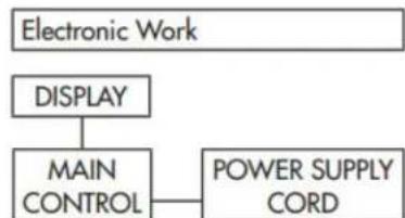
flowchart
graph TD
    A["Electronic Work"] --> B["DISPLAY"]
    B --> C["MAIN CONTROL"]
    C --> D["POWER SUPPLY CORD"]
OPERATING INSTRUCTIONS
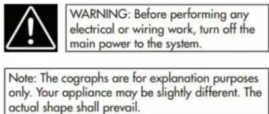
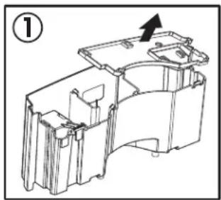
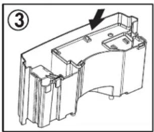
CASTER INSTALLATION
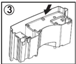
The casters and power cord can be found inside the water bucket.
- Remove the bucket from the appliance and remove the bucket cover.
- Remove the casters and power cord from the water bucket.
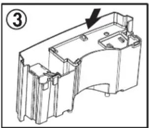
- Replace the bucket cover and replace the bucket inside the appliance.
- Tilt the appliance to a 45^ angle. Push the casters into the bottom of the appliance until they click. Ensure the ring around the caster is flush against the bottom of the appliance.
natural_image
Technical line drawing of a mechanical housing or enclosure with internal components and an arrow indicating direction (no text or symbols present)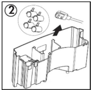
natural_image
Technical line drawing of a mechanical housing component with an arrow indicating a specific part (no text or symbols present)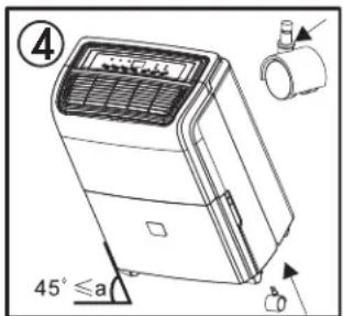
OPERATION
- Place the dehumidifier on a smooth, level floor that is strong enough to support the appliance with a full bucket of water.
- Do not place the dehumidifier on carpeting as this can block air flow around the appliance.
- Do not force casters to move over carpeting as the appliance can become unbalanced and spill water.
- To maintain efficiency, operate the appliance in an enclosed area. Keep nearby doors and windows closed.
- Any time the appliance is placed on its back or side, it must be allowed to stand upright for 6 hours before plugging in to avoid damage to internal components.
- Maintain a minimum clearance of 45 cm (18 inches) on all sides of the appliance to allow for proper air circulation.
- The recommended ambient operating temperature is between 5°C (41°F) and 32°C (90°F).
- The recommended ambient operating humidity is between 30 - 90%.
- The default humidity setting is 50% and low fan speed. Depending on humidity conditions the dehumidifier may not start automatically under the default setting. This means the humidity in the surrounding air is less than 50%. Press the down button to lower the set humidity until the set humidity is lower than the ambient humidity.
- For optimal performance, ensure that the humidity setting is 10% lower than the ambient humidity. It is normal for the ambient humidity to vary up to 5% above or below the set humidity.
- It is recommended in normal conditions to set the humidity between 40-45%.
- It is normal for the dehumidifier to exhaust warm air from the top.
OPERATING INSTRUCTIONS
CONTROL PANEL TIMER FUNCTION
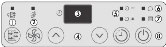
- Filter Button and Indicator Light: The filter light will illuminate when the filter needs to be cleaned, approximately every 250 hours of operation. Press the filter button once the filter has been cleaned to return to regular functioning.
- Fan Button and Indicator Light: Press to set the fan speed to low or high. The light will illuminate on high fan speed and will turn off on low fan speed.
- Display: Shows the actual room humidity to a ± 5% accuracy in a range of 35% to 80% relative humidity. Displays selection when programming humidity or timer.
- Up and Down Buttons: The humidity level can be set within a range of 35% to 80% relative humidity in 5% increments using these buttons. For drier air, press the down button and set to a lower percentage value. For more damp air, press the up button and set a higher percentage value.
- Timer Button and Indicator Lights: Press to initiate the auto-start and auto-stop feature. Set a start or stop time from 0.0 to 24 hours using the up and down buttons.
- Continuous Mode: To reach continuous mode, press the down button until CO shows on the display. This setting will disregard the ambient humidity and will run the compressor continuously to reach the driest conditions possible.
- Full Bucket Indicator Light: When the bucket is full or incorrectly positioned the full bucket light will turn on and remain on until the bucket is emptied or correctly re-positioned. The compressor and fan motor operation will stop. When the bucket is emptied or correctly repositioned the dehumidifier will resume operation automatically. It may take 2-3 minutes before operating conditions resume.
- Power Button: Use this button to turn the appliance on or off.
Auto Off Function
- When the appliance is turned on, press the timer button to activate the auto-stop timer. The auto-stop light will illuminate.
- Press the up and down buttons to change the set time in 0.5 hour increments up to 10 hours and then in 1 hour increments up to 24 hours.
- 5 seconds of after setting the time for the timer, the Timer symbol will illuminate to indicate the timer is now active.
Auto On Function
- When the appliance is turned off, press the timer button to activate the auto-start timer. Set the time as per the instructions above. 5 seconds of after setting the time for the timer, the Timer symbol will illuminate to indicate the timer is now active.
Turning the appliance on or off at any time or changing the timer setting to 0.0 will cancel the timer settings.
MEMORY AND AUTO RESTART SETTINGS
Each time the appliance is disconnected or reconnected or in the event of a power failure, the appliance will default to the last program setting that was used.
If the appliance shuts off unexpectedly due to a power failure, it will restart with the previous settings automatically once power resumes.
AUTOMATIC DEFROST
If the appliance is operating in an environment where the ambient temperature is very cold, frost may form on the evaporator coils. The compressor will cycle off but the fan will continue to run until the frost melts. An error code may show on the control panel display.
When the frost has melted, the compressor function will resume and the appliance will return to regular operation.
To ensure frost does not form on the evaporator coils, ensure the ambient temperature around the appliance is at a comfortable level. Higher ambient temperature will also help to remove humidity from the air.
OPERATING INSTRUCTIONS
WATER REMOVAL
There are two ways to remove collected water from the appliance.
1. Water Bucket
The dehumidifier will automatically collect condensed water in the water bucket. When the bucket is full or displaced inside the unit, the float actuator inside the bucket breaks contact with the safety switch. The compressor will shut down, preventing moisture from being condensed. The fan will continue to run for approximately 2-3 minutes. Water may drip onto the base of the appliance and onto the floor. Make sure to protect flooring when emptying the water bucket.
Never tamper with or attempt to defeat the water level float system. Proper installation of the water bucket is crucial in maintaining reliable operation.
To empty the bucket, gently remove it from the appliance by gripping both sides and pulling outward. Be cautious when removing the bucket, it will be full and can be heavy.
Do not place the water bucket directly on the floor. The bottom of the bucket is uneven and it will fall over and spill water.
Empty the bucket and replace it in the appliance. The dehumidifier will not function without the bucket installed.
The bucket should be cleaned every few weeks to prevent mold growth. Only use mild detergent to clean the bucket; do not use harsh chemicals or bleach.
2. Continuous Drain
Water can be removed from the appliance using the continuous drain and the provided drain hose.
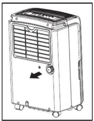
Before using any automatic drain functions, check that all drain ports are clean and free of debris. There are either one or two drain ports inside the bucket compartment of the appliance, remove the bucket to see them. There are one or two drain ports on the back of the appliance where the drain hoses attach. All drain ports should be cleaned with a pipe cleaner prior to use.
Note: Do not clean the drain ports with anything more rigid than a pipe cleaner as this can damage the appliance.
Note: If the drain ports are clogged or dirty it can cause water to leak from the bottom of the appliance.
Remove the cover from the continuous drain outlet and attach the provided continuous drain connector and the provided drain hose. Direct the other end of the hose to a bucket or floor drain.
Ensure that the hose is not bent and goes straight down from the back of the appliance. The continuous drain is only activated by gravity so any bends or upward motion in the hose will stop the water from draining.
Note: A garden hose can also be used as a continuous drain hose. The garden hose should be cut so that it is no more than 1.8 m (6 feet) long. If the drain hose is too long water may not drain completely which can lead to stagnant water and mildew build up inside the hose.
natural_image
Line drawing of a portable air conditioner unit with ventilation grilles and wheels (no text or symbols)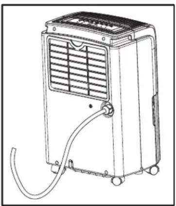
natural_image
Line drawing of a portable air conditioner unit with ventilation grilles and coiled tubing (no text or symbols)CARE & MAINTENANCE
AIR FILTER
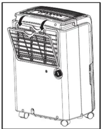
The filter indicator will illuminate after 250 hours of use, indicating that the filter should be cleaned.
Remove the filter from the back of the appliance. Use a vacuum to remove dust from the filter or wash with warm water and mild detergent. Ensure the filter is completely dry before replacing it in the appliance. Press the filter button to reset the filter indicator.
Note: Do not operate the appliance without the air filter installed.
natural_image
Line drawing of a portable air conditioner unit with cooling fins and wheels (no text or symbols)LONG TERM STORAGE
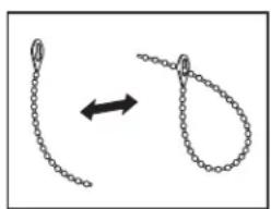
Ensure that the inside of the appliance is dry before storing for the off season to help avoid the growth of mold or mildew. Ensure the filter is clean and dry. Secure the power cord with the power cord strap as per the image below. Store the appliance upright and covered in a dry location.
natural_image
Diagram showing two connected chain loops with an arrow indicating direction (no text or symbols)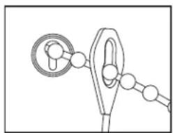
natural_image
Pure mechanical diagram showing a clamp or clamping device with no text, numbers, or symbols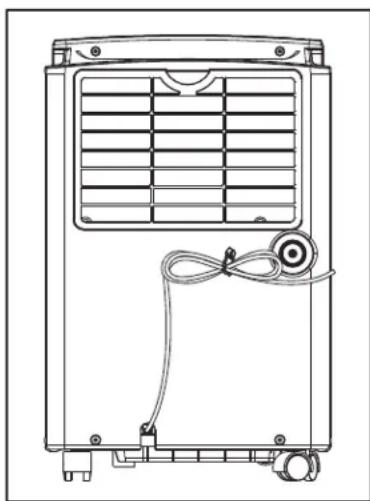
natural_image
Line drawing of a portable air conditioner unit with ventilation grilles and coiled cable (no text or symbols)CLEANING
To avoid possible electric shock, ensure that the appliance is unplugged before performing any cleaning or maintenance.
The outside of the appliance can be wiped clean with a soft cloth or with a lukewarm, damp cloth if necessary.
Do not use gasoline, benzene, thinner or any other chemicals to clean this appliance as these substances can cause damage to the finish and deformation of plastic parts.
Never pour water directly onto the appliance as this will cause deterioration of electrical components and wiring insulation.
Ensure that the drain ports on the interior of the appliance and the drain ports on the back of the appliance are free of dirt and calcium build up.
ERROR CODES
EH - humidity sensor fault
E1 or E2 - temperature sensor fault
E3 - Gas leakage
DISPOSAL
This appliance may not be treated as regular household waste, it should be taken to the appropriate waste collection point for recycling of electrical components. Check for local regulatory compliance regarding approved and safe disposal of this appliance.
TROUBLESHOOTING
Danby Consumer Care: 1-800-263-2629
Hours of operation:
Monday to Thursday 8:30 am - 6:00 pm Eastern Standard Time
Friday 8:30 am - 4:00 pm Eastern Standard Time
Information in this manual is subject to change without notice.
PROBLEM POSSIBLE CAUSE
| Appliance will not operate • Plug is not fully inserted into the wall outlet• Blown fuse or circuit breaker• Ambient humidity is lower than the set humidity• Bucket is full or is not in the proper position |
| Insufficient dehumidifying • Air filter is dirty• Blocked air flow• Appliance size is too small for application• Ambient humidity is lower than the set humidity |
| Noise • Air filter is dirty• Bucket is not in proper position• Floor surface is not level |
| Odors • Formation of mold or mildew on internal wet surfaces• Place an algaecide tablet in the water bucket |
| Water on floor • Hose connection is loose• Drain cover has been removed |
| Frost build up• When ambient temperature is below 5°C (41°F) frost may form• Switch the appliance to fan only mode until the frost melts |
LIMITED "CARRY IN" WARRANTY
This quality product is warranted to be free from manufacturer's defects in material and workmanship, provided that the unit is used under the normal operating conditions intended by the manufacturer.
This warranty is available only to the person to whom the unit was originally sold by Danby Products Limited (Canada) or Danby Products Inc. (U.S.A.) (hereafter "Danby") or by an authorized distributor of Danby, and is non-transferable.
TERMS OF WARRANTY
Plastic parts are warranted for thirty (30) days from the date of purchase, with no extensions provided.
First 24 months
During the first twenty four (24) months, any functional parts of this product found to be defective, will be repaired or replaced, at warrantor's option, at no charge to the original purchaser.
To obtain service
Contact the dealer where the unit was purchased, or contact the nearest authorized Danby service depot, where service must be performed by a qualified service technician. If service is performed on the unit by anyone other than an authorized service depot, all obligations of Danby under this warranty shall be void.
It is the responsibility of the purchaser to transport the appliance to the nearest authorized service depot.
Transportation charges to and from the service location are not protected by this warranty and are the responsibility of the purchaser.
Nothing within this warranty shall imply that Danby will be responsible or liable for any spoilage or damage to food or other contents of this appliance, whether due to any defect of the appliance, or its use, whether proper or improper.
EXCLUSIONS
Save as herein provided, by Danby, there are no other warranties, conditions, representations or guarantees, express or implied, made or intended by Danby or its authorized distributors and all other warranties, conditions, representations or guarantees, including any warranties, conditions, representations or guarantees under any Sale of Goods Act or like legislation or statute is hereby expressly excluded. Save as herein provided, Danby shall not be responsible for any damages to persons or property, including the unit itself, howsoever caused or any consequential damages arising from the malfunction of the unit and by the purchase of the unit, the purchaser does hereby agree to indemnify and hold harmless Danby from any claim for damages to persons or property caused by the unit.
GENERAL PROVISIONS
No warranty or insurance herein contained or set out shall apply when damage or repair is caused by any of the following:
1) Power failure.
2) Damage in transit or when moving the appliance.
3) Improper power supply such as low voltage, defective house wiring or inadequate fuses.
4) Accident, alteration, abuse or misuse of the appliance such as inadequate air circulation in the room or abnormal operating conditions (i.e. extremely high or low room temperature).
5) Use for commercial or industrial purposes (i.e. If the appliance is not installed in a domestic residence).
6) Fire, water damage, theft, war, riot, hostility, acts of God such as hurricanes, floods etc.
7) Service calls resulting in customer education
8) Improper Installation (ie. Building-in of a free standing appliance or using an appliance outdoors that is not approved for outdoor application, including but not limited to: garages, patios, porches or anywhere that is not properly insulated or climate controlled).
Proof of purchase date will be required for warranty claims; retain bills of sale. In the event that warranty service is required, present the proof of purchase to our authorized service depot.
Warranty Service
Carry In
Danby Products Limited
PO Box 1778, Guelph, Ontario, Canada N1H 6Z9
Telephone: |519| 837-0920 FAX: |519| 837-0449
1-800-263-2629
04/17
Danby Products Inc
PO Box 669, Findlay, Ohio, U.S.A. 45840
Telephone: (419) 425-8627 FAX: (419) 425-8629
Bienvenue
A2L
ISO 817
ATTENTION : RISQUE
D'INCENDIE
RÉFRIGÉRANT
INFLAMMABLE
AVERTISSEMENT:
natural_image
Technical line drawing of a mechanical housing or enclosure with an arrow indicating direction (no text or symbols present)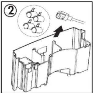
natural_image
Technical line drawing of a mechanical housing component with an arrow indicating a feature (no text or symbols present)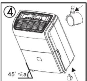
OPÉRATION
natural_image
Line drawing of a portable air conditioner unit with ventilation grilles and wheels (no text or symbols)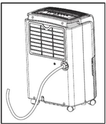
natural_image
Line drawing of a portable air conditioner unit with ventilation grille and coiled tubing (no text or symbols)SOINS ET MAINTENANCE
FILTRE À AIR
natural_image
Line drawing of a portable air conditioner unit with cooling fins and wheels (no text or symbols)natural_image
Diagram showing two coiled ropes with one pointing left and the other right (no text or symbols)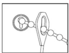
natural_image
Pure mechanical diagram showing a clamp or clamping device with no text, numbers, or symbols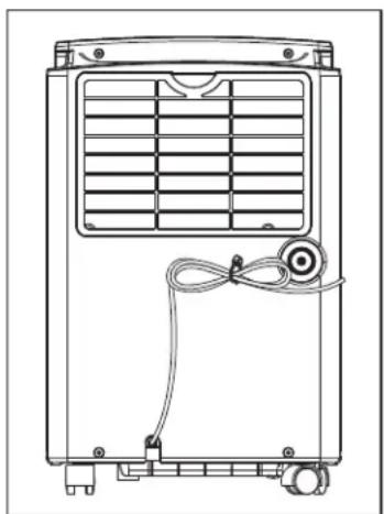
natural_image
Line drawing of a front view of an air conditioner unit with ventilation grilles and coiled cable (no text or symbols)NETTOYAGE
PROBLÈME CAUSE POSSIBLE
Danby Products Limited
PO Box 1778, Guelph, Ontario, Canada N1H 6Z9
natural_image
Technical line drawing of a mechanical housing component with an arrow indicating direction (no text or symbols present)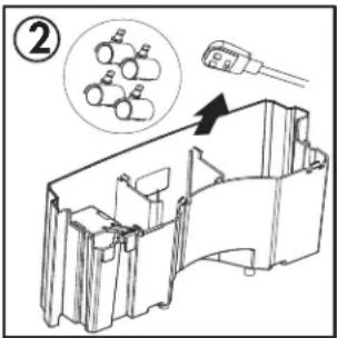
natural_image
Technical line drawing of a mechanical housing component with an arrow indicating direction (no text or symbols present)
OPERACIÓN
natural_image
Line drawing of an air conditioner unit with ventilation grilles and a directional arrow (no text or symbols)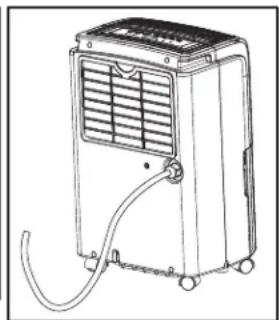
natural_image
Line drawing of a portable air conditioner unit with ventilation grille and coiled tubing (no text or symbols)natural_image
Line drawing of a portable air conditioner unit with ventilation grilles and wheels (no text or symbols)ALMACENAMIENTO A LARGO PLAZO
LIMPIEZA
PROBLEMA CAUSA POSIBLE
Danby Products Limited
PO Box 1778, Guelph, Ontario, Canada N1H 6Z9
Telephone: (519) 837-0920 FAX: (519) 837-0449
1-800-263-2629
04/17
Danby Products Inc.
PO Box 669, Findlay, Ohio, U.S.A. 45840
Telephone: (419) 425-8627 FAX: (419) 425-8629
NOTES / REMARQUES / NOTAS :
DDR040EB2WDB
Danby Products Limited, Guelph, Ontario, Canada N1H 6Z9
Danby Products Inc. Findlay, Ohio, U.S.A. 45840
www.danby.com