
MDT24H14ASTC - Dishwasher MIDEA - Free user manual and instructions
Find the device manual for free MDT24H14ASTC MIDEA in PDF.

| Product Type | Built-in Dishwasher 14 Place Settings |
| Brand | Midea |
| Model | MDT24H14ASTC |
| Electrical Supply | 120 V, 60 Hz, dedicated 15 or 20 A circuit |
| Capacity | 14 place settings |
| Required Opening Dimensions (W x H x D) | Min. width 24 in (61 cm), max. height 35 in (88.9 cm), min. depth 25 5/8 in (65.1 cm) in front of appliance |
| Water Supply Pressure | 20 to 120 psi (138 to 862 kPa) |
| Recommended Water Temperature | 49 °C to 65.5 °C (120 °F to 150 °F) |
| Electrical Connection | Direct wire or power cord with ground plug (3-prong) |
| Water Connection | 3/8 in diameter copper tube, 90° elbow with thread tape |
| Drain Connection | Drain hose provided, max length 10 ft (3.05 m), min drain loop 32 in (81.3 cm) |
| Leveling | Adjustable front and rear feet; level required for optimal performance |
| Securing | Mounting brackets for countertop or adjacent cabinets |
| Safety | Grounding mandatory; lockable door; anti-tip protection |
| Maintenance | Regular filter cleaning; pump seal lubricated at installation |
| Available Spare Parts | Power cord # BK500, drain hose, 90° elbow, mounting clips |
| Repairability | Possible removal of tub for service; access to terminal box |
| User Manual | Manual provided in multiple languages, available in PDF upon request |
Frequently Asked Questions - MDT24H14ASTC MIDEA
User questions about MDT24H14ASTC MIDEA
0 question about this device. Answer the ones you know or ask your own.
Ask a new question about this device
Download the instructions for your Dishwasher in PDF format for free! Find your manual MDT24H14ASTC - MIDEA and take your electronic device back in hand. On this page are published all the documents necessary for the use of your device. MDT24H14ASTC by MIDEA.
USER MANUAL MDT24H14ASTC MIDEA
Capacity: 14 Place Settings
Installer: Be sure to leave these instructions for the consumer's and local inspector's use.
Homeowner: Keep these instructions with your User Manual for future reference.
version A-11-2023
INSTALLATION INSTRUCTIONS
natural_image
Exterior view of a stainless steel kitchen appliance (no visible text or symbols)DISHWASHER SAFETY ....3
INSTALLATION REQUIREMENTS ....5
Tools and Parts ....5
Location Requirements ....7
Drain Requirements 9
Water Supply Requirements ....10
Electrical Requirements ....10
INSTALLATION INSTRUCTIONS ......11
Unpack Dishwasher 11
Check Door Balance 12
Remove Kick Plate 13
Adjust Leveling Legs 13
Install 90° Elbow ....14
Prepare Installation Opening 15
Verify Existing Utility Connections 16
When There Are No Existing Utility Connections 17
Install Mounting Brackets 19
Connect Drain Hose to Dishwasher 21
Slide Dishwasher Partially Into Opening 21
Level Dishwasher 22
Connect to Power Supply 23
Connect to Water Supply 26
Connect to House Drain System 27
Secure Dishwasher....31
Pre-Test Checklist 33
Test Dishwasher 34
Replace the Kick Plate.... 35
DISHWASHER SAFETY
YOUR SAFETY AND THE SAFETY OF OTHERS ARE VERY IMPORTANT
To prevent injury to the user or other people and property damage, the instructions shown here must be followed. Incorrect operation due to ignoring of instructions may cause harm or damage, including death.
The level of risk is shown by the following indications.

WARNINGWARNING
This symbol indicates the possibility of death or serious injury.

CAUTION
This symbol indicates the possibility of injury or damage to property.

WARNING
This symbol indicates the possibility of dangerous voltage constituting a risk of electrical shock is present that could result in death or serious injury

WARNING/GROUNDING INSTRUCTIONS
Improper connection of the equipment-grounding conductor can result in a risk of electric shock. Check with a qualified electrician or service representative if you are in doubt whether the appliance is properly grounded. Do not modify the plug provided with the appliance. If the plug will not fit the outlet, have a proper outlet installed by a qualified electrician.
For a grounded, cord-connected appliance:
This appliance must be grounded. In the event of a malfunction or breakdown, grounding will reduce the risk of electric shock by providing a path of least resistance for electric current. This appliance is equipped with a cord having an equipment-grounding conductor and a grounding plug. The plug must be plugged into an appropriate outlet that is installed and grounded in accordance with all local codes and ordinances.
For a permanently connected appliance:
This appliance must be connected to a grounded metal, permanent wiring system, or an equipment-grounding conductor must be run with the circuit conductors and connected to the equipment-grounding terminal or lead on the appliance.

WARNING

natural_image
Simple black-and-white illustration of a tilted book with a flat base (no text or symbols)Tip Over Hazard
- Do not use dishwasher until completely installed.
- Do not push down on open door.
- Doing so can result in serious injury or cuts.

WARNING
Suffocation Hazard
- Before you throw away your old appliance, remove the door or lid so that children cannot hide or get trapped inside your old appliance.
- Failure to follow these instructions can result in death or brain damage.

WARNING

Electrical Shock Hazard
To reduce the risk of electric shock, fire or injury to persons:
- The installer must ensure that the dishwasher is completely enclosed at the time of installation.
- Care shall be exercised when the dishwasher is installed or removed to reduce the likelihood of damage to the power cord.
State of California Proposition 65 Warnings:

WARNING: Cancer and Reproductive Harm
-www.P65Warnings.ca.gov.
INSTALLATION REQUIREMENTS
TOOLS AND PARTS
Gather the required tools and parts before starting installation.
PARTS SUPPLIED
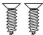
Flat-head Wood Screws (4)
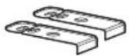
Top-mounting Clips (2)
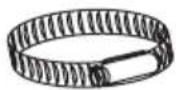
Screw-type Hose Clamp Drain Hose
PARTS NEEDED (NOT PROVIDED)

3/4" FHT × 3/8" OD
compression 90 ELbow (if not included in in hose kit)
Thread Seal Tape UL Listed Wire Nuts (3)
Power Supply Cord Kit
B K 500 or
Electric Cable (Optional)
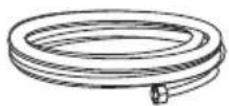
Copper Tubing Water Line ( ^3/_8 " min.)
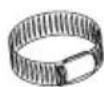
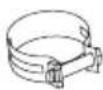
Hose Clamps
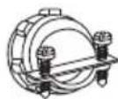
Strain Relief
TOOLS NEEDED
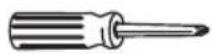
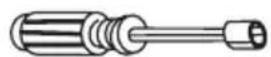
Phillips-head Screwdriver
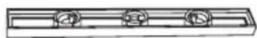
5/16'' and 1/4'' Nutdriver Level
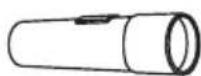
Flashlight 6" A
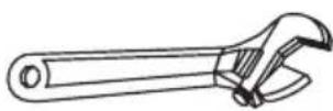
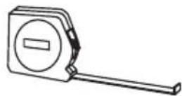
djustable Wrench Measuring Tape
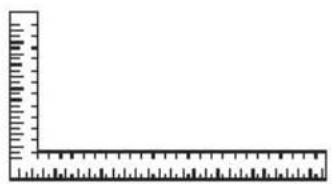
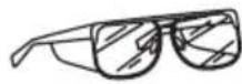
Carpenters Square Safety Glasses Bucket
Gloves
Flat-bladed Screwdriver
NEW INSTALLATIONS (ONLY)
Parts Needed
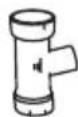
Hand Shut-off Valve Waste Tee
(house plumbing, if applicable)
Air Gap for drain hose (if required)
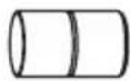
Coupler (extending drain line, if applicable)
Tools Needed
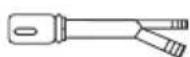
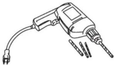
Tubing Cutter Hole Sa
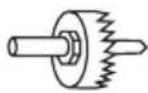
natural_image
Line drawing of a handheld electric drill with multiple drill bits (no text or symbols)w Set Drill and Bits
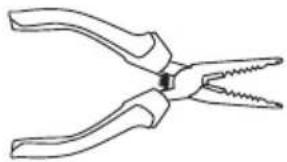
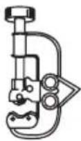
natural_image
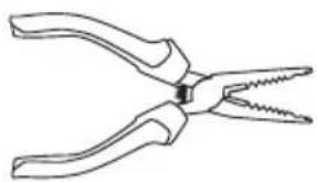
Line drawing of a pair of pliers with metal jaws (no text or symbols)Wire Stripper
LOCATION REQUIREMENTS
IMPORTANT:
- Do not run drain lines, water lines or electrical wiring where they can interfere with or contact dishwasher motors or legs.
- The location where the dishwasher will be installed must provide clearance between motors and flooring. Motors should not touch the floor.
- The opening must have a level floor. (If floor at front of opening is not level with floor at rear of opening, shims may be needed to level dishwasher).
- Do not install dishwasher over carpeted flooring.
- The dishwasher must be fully enclosed on the top, sides and back and must not support any part of the enclosure.
- The dishwasher must be installed so that the drain hose is no more than 10 ft in length for proper drainage.
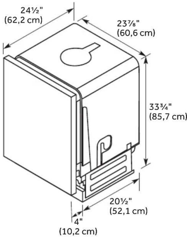
OPENING DIMENSIONS
- The rough cabinet opening must be at least 24" (61 cm) wide and a maximum of 35" (88.9 cm) in height, and provide easy access to water, electricity and a drain.
- When installed in a corner location, a 2" (5.1 cm) minimum clearance is required between the side of the dishwasher and the adjacent wall, cabinet or other appliance.
- There must be a minimum clearance of 25 ^5/8 " (65.1 cm) in front of the dishwasher to allow the door to fully open.
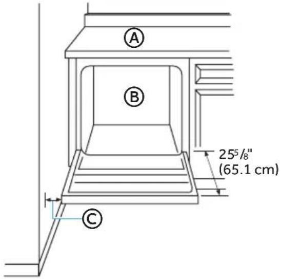
Ⓐ Countertop
B Dishwasher
© Clearance for Door Opening 2" Minimum
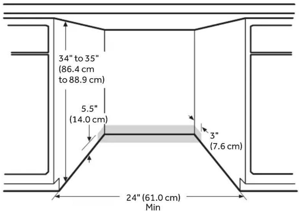
* Make sure water line, wires and drain hose are within the shaded area.
PRODUCT DIMENSIONS

DRAIN REQUIREMENTS
Follow local codes and ordinances.
DRAIN HOSE
Use the new drain hose supplied with your dishwasher. If the supplied hose is not long enough, use a new drain hose with a maximum length of 10 ft (3.05 m) that meets all current AHAM/IAPMO test standards.
The drain hose should:
- Be resistant to heat and detergent
- Have an inside diameter (I.D.) of 5 / 8'' (1.58 cm) or 7 / 8'' (2.2 cm)
- Include a coupler to connect the two hose ends (secure the connection with two clamps)
Do NOT connect drain hoses from other appliances to the dishwasher drain hose.
Drain Hose Routing
The drain hose may pass through the same hole as the wiring and hot water line, or you can cut an additional 1½ " (3.8 cm) diameter hole in the cabinet wall to admit the drain hose.
NOTE: The hole must be smooth with no sharp edges.
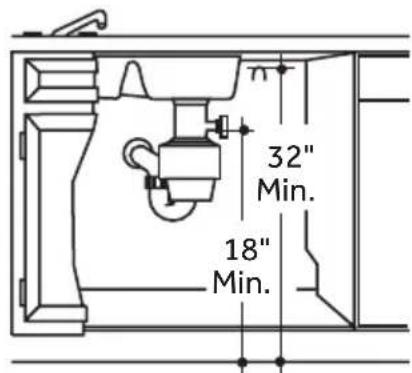
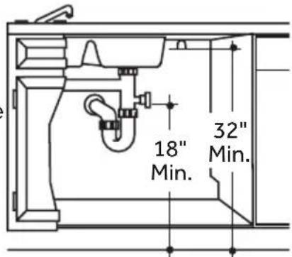
DRAIN CONNECTION HEIGHT
The drain connection method depends on the height of the drain hose connection.
IMPORTANT: Failure to connect the drain hose at a height of 18" with air gap (not provided) OR to create a drain loop with a minimum height of 32" (81.3 cm) will result in improper draining of the dishwasher.
WATER SUPPLY REQUIREMENTS
- Water pressure from the hot water supply line must be between 20-120 psi (138-862 kPa).
- Water heater that is adjusted to a water temperature of 120°F to 150°F (49°C to 65.5°C).
- A 90° elbow is required to be attached to the water valve, prior to the connection of the water line.
- A 38 " min. diameter copper tubing water line extending at least 24" (61 cm) from the rear wall, and routed to connect to the front left-hand side of the dishwasher.
- A hand shut-off valve in an accessible location, such as under the sink (optional, but strongly recommended).
ELECTRICAL REQUIREMENTS

WARNING

Electrical Shock Hazard
- Installation and service must be performed by a qualified installer or service agency.
- Always disconnect the power before servicing this unit.
- This appliance must be properly grounded.
- Failure to do so could result in death, fire, or electrical shock.
IMPORTANT:
- The dishwasher must be supplied with 120 volt, 60 Hz., and connected to a dedicated, properly grounded branch circuit, protected by a 15 or 20 ampere circuit breaker or time delay fuse.
- Maximum of two field wiring supply conductors (12 AWG Maximum) plus one grounding conductor are permitted in the terminal box.
- Use Only copper wire.
- Wiring must be 2-wire with ground.
- Use a UL Listed/CSA Approved metallic strain relief.
- Be sure that the electrical connection and wire size are adequate and in conformance with the National Electrical Code, ANSI/NFPA No. 70-latest edition and all local codes and ordinances.
- If the electrical supply does not meet the above requirements, call a licensed, qualified electrician before proceeding.
Grounding Instructions:
- The dishwasher must be connected to a grounded metal, permanent wiring system, or an equipment grounding conductor must be run with the circuit conductors and be connected to the equipment grounding terminal or lead on the dishwasher.
Power Cord Connections:
- Use a power cord with connections that comply with the National Electrical Code, Section 422 and/or local codes and ordinances.
- Recommended cord length is 54" min. and 64" max.
- A power cord kit #BK500 is available for purchase from an authorized parts dealer.
Direct Wire Connections:
- Use flexible, armored or nonmetallic sheathed, copper wire with grounding wire that meets the wiring requirements for your local codes and ordinances.
INSTALLATION INSTRUCTIONS
IMPORTANT:
- This appliance should be installed only by a qualified Installer, plumber or technician and in accordance with the manufacturer's installation instructions, electrical and plumbing national and local codes and ordinances.
- The dishwasher must be installed to allow for future removal from the enclosure if service is required.
- Each dishwasher is tested at the factory and may contain some residual water in the tub as a result of the test.
UNPACK DISHWASHER
IMPORTANT: If you received a damaged dishwasher, you should immediately contact Midea Customer Service.

WARNING

Suffocation Hazard
- To avoid danger of suffocation, keep plastic bag and other packing material away from babies and children. Do not use this bag in cribs, carriages and playpens. The plastic bag could block nose and mouth and prevent breathing. This bag is not a toy.
- Failure to follow these instructions can result in death or brain damage.

WARNING
Suffocation Hazard
- Before you throw away your old appliance, remove the door or lid so that children cannot hide or get trapped inside your old appliance.
-
Failure to follow these instructions can result in death or brain damage.
-
With the help of two or more people, open the dishwasher door slowly while one person presses down on the top of the dishwasher. Remove the drain hose, lower dish rack and all packing material.
- Locate the literature package, and read the User Manual for operating instructions.
- Close the dishwasher door until latched, and stand the dishwasher upright.
- Properly dispose of/recycle all packing material.
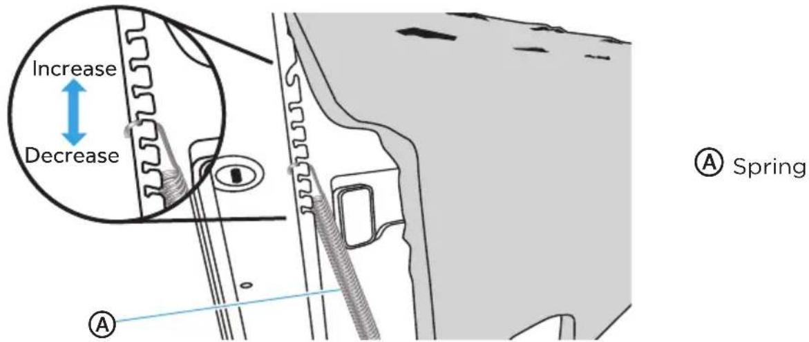
CHECK DOOR BALANCE
With another person holding the dishwasher to prevent it from tipping, open the door slowly.
- If the door drops when released, increase the spring tension.
- If the door closes when released, decrease the spring tension.
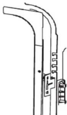
To adjust the spring tension:
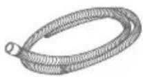
- Grasping the spring firmly, raise or lower the hook end to the next higher or lower slot, and then insert the hook into the slot.
NOTE: Adjust both springs (left-hand side and right-hand side) to the same tension. - Retest the door. Continue moving the spring hooks higher or lower until the door is balanced.
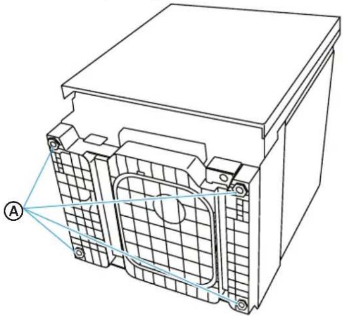
REMOVE KICK PLATE
- Using a screw driver, remove the two screws attaching the kick plate to the cabinet.
- Lift off the kick plate.
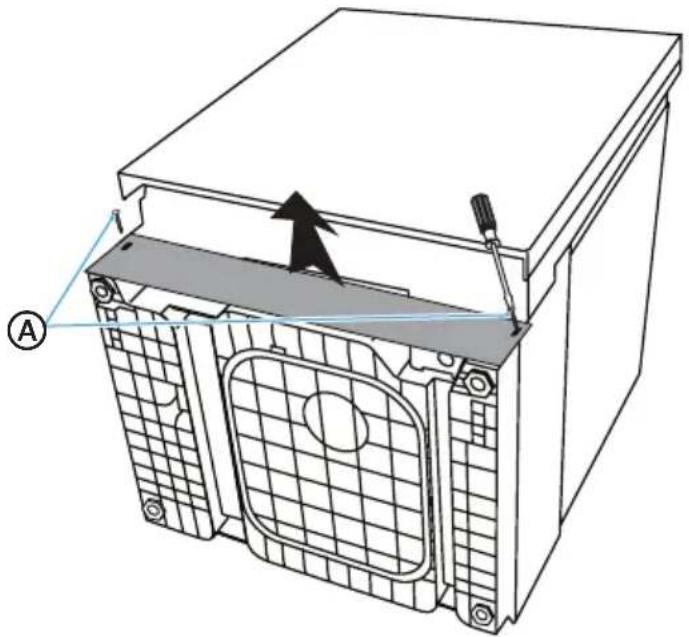
natural_image
Technical diagram of a mechanical housing with internal components and a tool, showing no text or symbols.Ⓐ Kick Plate Screws (2)
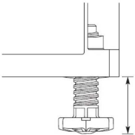
ADJUST LEVELING LEGS
- Move the dish washer close to the installation location and lay it on its back.
-
Measure the height of the opening from the underside of countertop to floor (lowest point).
-
Extend the lev eling legs from the base of the dishwasher by the length indicated in the following chart. Take into account any built-up flooring which may need to be added to the rear foot adjustment.
NOTES:
- If the floor was built up in for the front of the dishwasher, account for this difference when adjusting the rear leveling legs.
- Final leveling leg adjustments will be made following installation into the opening.
natural_image
Technical line drawing of a battery pack with internal components and labeled point A (no text or symbols beyond label)A
djust Leveling Legs to Installation Height
| Leveling Leg Adjustment | ||
| Opening Height Front L egs Back Legss | ||
| 34" 0 0 | ||
| 34 14 " 0 | 14 " | |
| 34 12 " | 14 " | 12 " |
| 34 34 " | 12 " | 34 " |
| 35" | 34 " 1" | |
natural_image
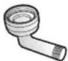
Technical line drawing of a mechanical assembly with a threaded bolt and vertical dimension line (no text or symbols)INSTALL 90° ELBOW
- Wrap the 90° elbo w with thread seal tape.
NOTES:
- Do not use plumber's putty.
-
To avoid damaging the water valve bracket and/or fitting, do not over tighten the elbow.
-
Position the end of the elbow so that it faces the bottom left of the dishwasher.
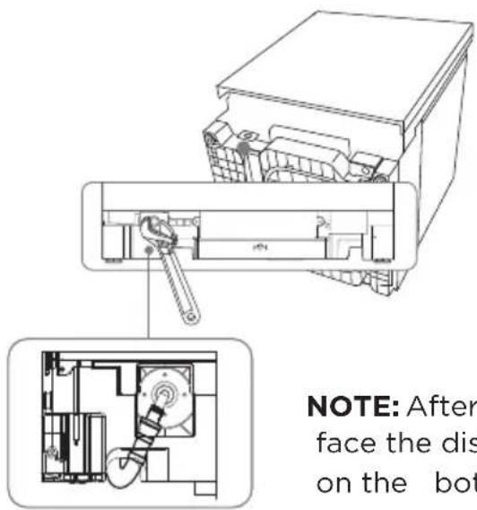
NOTE: After installation, the elbow should face the dishwasher card slot at the right on the bottom.
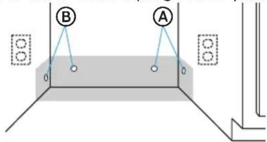
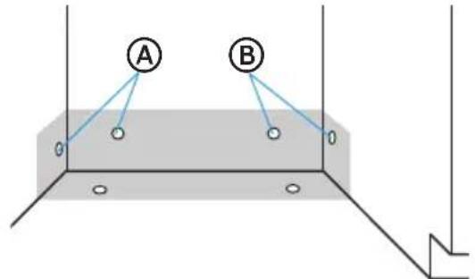
PREPARE INSTALLATION OPENING
- The wiring and plumbing may enter the opening from either the right-hand or left-hand side of the rear wall, the side cabinets, or the floor within the shaded area. See “Location Requirements” for dimensions.
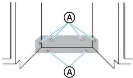
Ⓐ Possible Utility Hole Locations
NOTE: Connecting the dishwasher to utilities will be easier if you route the wiring into the installation opening from the right-hand side and the plumbing from the left-hand side.
IMPORTANT: Any plumbing or electrical line run outside of the shaded area can become pinched.
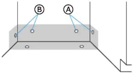
- The direct wire cable may enter the opening through either the same hole used for the drain hose and hot water line or through an additional 1½" (3.8 cm) diameter hole.
NOTE: The hole must be free of sharp edges. If the cabinet wall is metal, the edge of the hole must be covered with a bushing/grommet.
- Power cords with a plug MUST pass through a separate hole.
Ⓐ Preferred Electrical Locations
(B) Preferred Plumbing Locations
VERIFY EXISTING UTILITY CONNECTIONS
WATER CONNECTION
- Check that the water line reaches to the front, left-hand side of opening where the water connection will be made as shown in the following diagram.
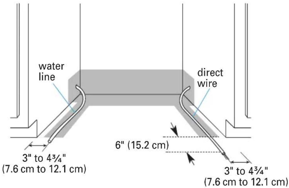
ELECTRICAL CONNECTION
Electrical Connection to Dishwasher
- Check that the direct wire cable extends a minimum of 6" beyond the front, right-hand side of the opening, and is routed as shown.
If the water line and the direct wire cable reach far enough to easily connect to the dishwasher, proceed to the next section "Install Mounting Brackets."
If the water line and the direct wire cable do NOT reach far enough, follow the instructions under "When There Are No Existing Utility Connections."
WHEN THERE ARE NO EXISTING UTILITY CONNECTIONS
PREPARE TO CONNECT POWER SUPPLY
Connect to the Power Supply using one of two Methods: Direct Wire Cable (Method 1) or Power Cord (Method 2). Follow the instructions specific to your installation.

WARNING

Electrical Shock Hazard
- Disconnect electrical power at the fuse box or circuit breaker box before installing dishwasher.
● Failure to do so can result in death or electrical shock.
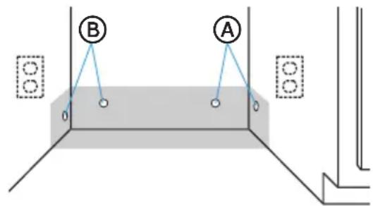
Method 1 - Direct Wire
- Drill a 34 " (1.9 cm) hole into the right-hand cabinet, or the right-hand side of the back wall or floor of the opening. See following graphic for preferred and optional locations.
NOTE: Wiring the dishwasher will be easier if the wire is routed into the opening from the right-hand side.

Preferred Locations

Optional Locations
- Smooth or c over rough edges of the hole that the wiring will pass through.
Wood Cabinet - Sand edge of hole until smooth.
Metal Cabinet - Cover edge of hole with grommet (not provided).
- Route the cable from the power supply through the hole (cable must extend to the front, right-hand side of the opening). Extend cable to 6" (15.2 cm) in front of unit and tape the cable to the floor to keep it from moving when dishwasher is moved into the cabinet opening.

Method 2 - Power Supply Cord
IMPORTANT:
- The power cord and connections must comply with the National Electrical Code, Section 422 and/or local codes and ordinances. Recommended cord length is 54" min. and 64" max.
- A mating 3 prong, ground-type wall receptacle is required in a cabinet next to the dishwasher opening.
-
A power cord kit part #BK500 is available for purchase from an authorized parts dealer.
-
Drill a 1 12 " (3.8 cm) hole in the cabinet rear or side. Preferred and Optional locations are shown in the following graphic.
-
Smooth edges of hole for power cord.
Wood Cabinet - Sand edges of hole until smooth.
Metal Cabinet - Cover edges of hole with grommet (not provided).
- Attach power cord to dishwasher before moving it into the opening. See "Connect Power Supply" section for proper installation technique.
Ⓐ Preferred Locations
B Optional Locations

WARNING

Electrical Shock Hazard
- Plug into a grounded 3 prong outlet.
- Do not remove the ground prong from the power cord plug.
- Do not use an adapter.
- Do not use an extension cord.
- Failure to do so can result in death, fire or electrical shock.
PREPARE TO CONNECT WATER LINE
NOTE: Routing the water line through the left side of cabinet opening will make water connection easier.
- Drill a 12 " (1.3 cm) hole in the cabinet side, rear or floor. Preferred and optional locations are shown in the following graphic.
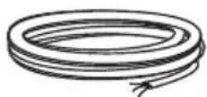
- Measure to determine the overall length of copper tubing required for the water line.
IMPORTANT: Slowly feed copper tubing through hole in cabinet. Copper tubing bends and kinks easily, so handle the tubing gently.
- Attach copper tubing to the manual shutoff valve.
A
Eferred Locations
B
Optional Locations
- Slowly feed the copper tubing through the hole into the opening. Continue feeding the tubing, until there is enough length to connect to the inlet (front, left-hand side of the dishwasher) yet remain within the required boundary.
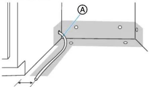
A
Copper Tubing
3" to 4 ^3/4 "
(7.6 cm to 12.1 cm)
- Slo wly turn water shutoff valve to "ON" position. Flush water into a shallow pan to get rid of particles that may clog the inlet valve.
- Turn shutoff valve to "OFF" position.
PREPARE TO CONNECT DRAIN HOSE
The drain hose will be connected to the house drain system after the dishwasher is installed in the opening.
- Drill a 1 12 " (3.8 cm) hole in cabinet wall or floor on the side of the opening closest to the sink.
natural_image
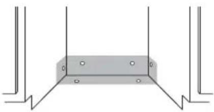
Pure structural diagram of a rectangular beam supported by vertical supports (no text or symbols)INSTALL MOUNTING BRACKETS
IMPORTANT: The dishwasher must be secured with mounting brackets to the countertop or adjacent cabinets to keep it from tipping when the door is opened.
Some countertop materials, such as granite, do not accept screws; and therefore, do not lend themselves to a countertop installation.
Follow the instructions to install mounting brackets in the manner required for your installation method. You will secure the dishwasher after it is connected to the utilities and moved into the opening.

WARNING
Excessive Weight Hazard
- Use two or more people to move and install dishwasher.
- Failure to do so can result in back or other injury.
Method 1 - Installation to Countertop
To enable you to secure the dishwasher to the countertop, install two mounting clips to the top of the dishwasher.
- With the help of two or more people, stand the dishwasher upright.
- Insert the mounting clips into the front, top slots of the dishwasher.
NOTE: The top mounting clips have a break off point, so a section of the clip can be removed, if necessary, to fit the depth of the cabinet.
Ⓐ Mounting Clips
(B) Break-off Point
© utb Flange
Method 2 - Installation to Adjacent Cabinets
- Remove the plastic tub caps from the inside of the dishwasher tub.
- Drive a wood screw through the hole in the side of the dishwasher into the cabinet frame.
IMPORTANT: Drive the screws straight and flush. Protruding screw heads will scratch the side of the dishwasher. This method is for attaching the dishwasher to the side of the cabinet, and it should be done when the countertop is made of granite or other breakable materials.
- Reinsert the plastic tub caps.
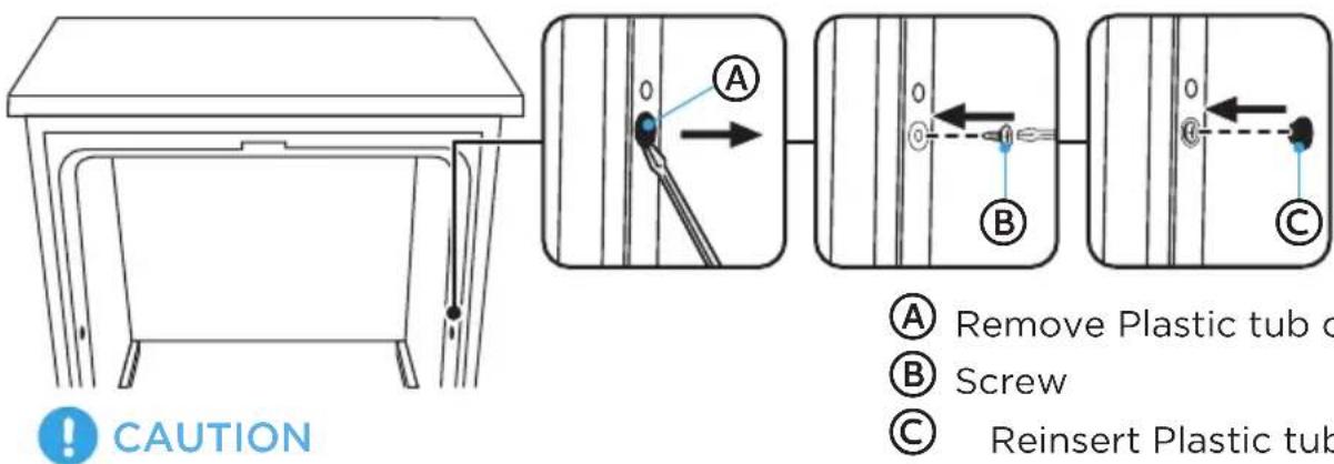
Do Not Overtighten Side Screws.
CONNECT DRAIN HOSE TO DISHWASHER
- Grasp the sides of the dishw asher at the edges of the door panel, and place the dishwasher in front of the opening.
- Insert the drain hose into the hole in the cabinet wall.
- Attach drain hose to the back of the dishwasher and secure with a hose clamp.
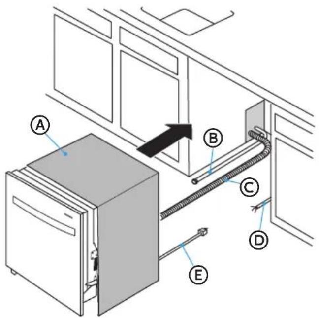
Ⓐ Insulation Blanket
⑧ Water Line
© Drain Hose (Maximum Length 10 ft [3.0 m])
House Wiring
E Power Cord (If Used)
SLIDE DISHWASHER PARTIALLY INTO OPENING

WARNING

natural_image
Simple black-and-white illustration of a tilted book with a flat base (no text or symbols)Tip Over Hazard
- Do not use dishwasher until completely installed.
- Do not push down on open door.
-
Doing so can result in serious injury or cuts.
-
Position power supply.
-
If dishwasher has a power supply cord, insert power supply cord into the hole cut into the cabinet.
-
If using a directwire connection, check that the wiring is on the right front side of opening.
-
Make sure the drain hose is not kinked under the dishwasher and there is no interference with the water line and wiring or any other component.
-
Slowly move the dishwasher into the opening a few inches at a time. As you proceed, pull the drain hose, water supply hose and cord through the opening under the sink or cabinet. Stop pushing when the dishwasher is a few inches in front of the adjacent cabinetry.
NOTE: Do not push against the front of the panel or on the console - they will dent.
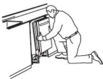
natural_image
Line drawing of a person kneeling beside a door with a cabinet (no text or symbols)Reposition dishwasher by grasping both sides with hands.
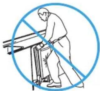
natural_image
Illustration of a person using a tool to cut through a blue circle (no text or symbols)Do not push against front door panel with knee. Damage to the door panel will occur.
- Push dishwasher completely into the opening so that the front corners of the dishwasher door are flush with the cabinet doors.
NOTE: It is all right if the dishwasher fits tightly into cabinet opening. Do not remove insulation blanket – the blanket reduces the sound level.
LEVEL DISHWASHER
IMPORTANT: Dishwasher must be level for proper dish rack operation and wash performance.
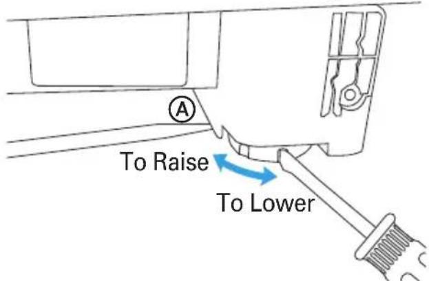
- Level the dishwasher so that its front panel is aligned with the adjacent cabinet doors.
NOTE: With some installations, it may be easier to adjust the front leg using a flat blade screwdriver.
• To Lower - Turn the leveling leg counterclockwise.
• To Raise - Turn the leveling leg clockwise.

Raise one side of the dishwasher
- Check that the leveling legs are firmly against the floor.
- Close and latch the door, and place level against the front panel. Check that dishwasher is plumb. If needed, adjust leveling leg or add shims until dishwasher is plumb.
NOTE: Shims must be securely attached to floor to prevent their movement when the dishwasher is operated.
-
Repeat for other side of dishwasher.
-
Place level on door and rack track inside the tub as shown. Check that dishwasher is level from side to side, and from back to front. If the dishwasher is not level, adjust front legs up or down until dishwasher is level.
Ⓐ Level Front to Back
(B) Level Side to Side
NOTE: Pull lower rack out about halfway. If the rack rolls forward or back into the dishwasher, the dishwasher must be leveled again.
CONNECT TO POWER SUPPLY
DIRECT WIRE CABLE

WARNING

Electrical Shock Hazard
• Electrically ground dishwasher.
- Connect ground wire to green ground connector in terminal box.
- Do not use an extension cord.
- Failure to follow these instructions can result in death, fire, or electrical shock.
IMPORTANT: Contact a qualified electrician. Be sure that the electrical connection and wire size are adequate and in conformance with the National Electrical Code, ANSI/NFPA No. 70-latest edition and all local codes and ordinances.
- Confirm that power is turned off at the source.
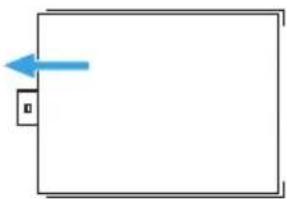
- Remove terminal box cover. Retain for later use.

natural_image
Simple diagram with a blue arrow pointing left and a small square inside, no text or symbols present.- Install a UL list ed/CSA approved strain relief.
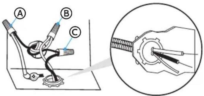
- Route the direct wire cable in the channel on the right-hand side of the dishwasher base. Make sure that the dishwasher is not resting on and/or pinching the wire.
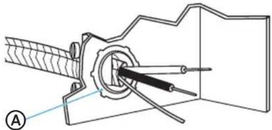
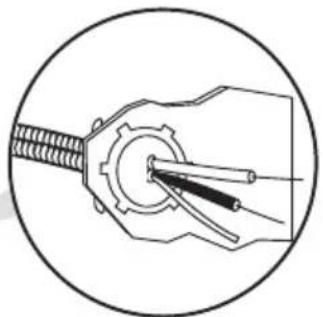
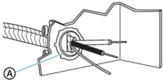
- Pull direct wire through strain relief in terminal box.
natural_image
Technical diagram of a mechanical assembly with labeled component (A), showing internal components and alignment lines (no text or symbols beyond label)
Strain Relief
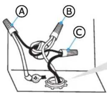
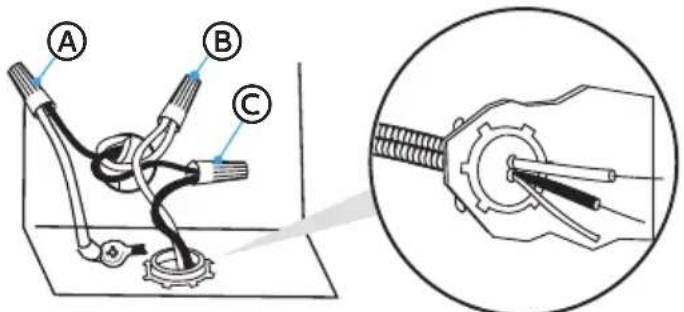
- Connect the wires as follows using UL listed wire nuts of the appropriate size to connect direct wire to 16-gauge dishwasher wire.
NOTES:
- Use UL listed wire nuts of the appropriate size to connect your household wiring to 16-gauge dishwasher wiring.
- Insert wire ends into twist on connector. Do not pre-twist bare wire.
- Twist connector.
- Gently tug on wires to be sure both wires are secured.
natural_image
Technical line drawing of a mechanical component with threaded shaft and central shaft (no text or symbols)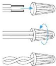
natural_image
Three diagrams showing twisted cable structures with arrows indicating deformation (no text or symbols)Ⓐ Ground
B White
© Black
- Tighten s train relief screws to secure cord.
- Reinstall terminal box cover with wire nuts inside terminal box.
- Make sure wires are not pinched by cover.
Ⓐ Ground
⑧ White
© Black
CONNECT POWER CORD

WARNING
Electrical Shock Hazard
- Plug into a grounded 3 prong outlet.
- Do not remove the ground prong from the power cord plug.
- Do not use an adapter.
- Do not use an extension cord.
- Failure to do so can result in death, fire or electrical shock.
IMPORTANT: The power cord and connections must comply with the National Electrical Code, Section 422 and/or local codes and ordinances. Recommended cord length is 54" min. and 64" max.
- Confirm that power is turned off at the source.
- Remove junction box cover. Retain for later use.
natural_image
Simple diagram with a blue arrow pointing to a small box on the left side of a rectangle (no text or symbols)- Install a UL listed/CSA approved strain relief.
- Route power cord in the channel on the right-hand side of the dishwasher base. Make sure that the dishwasher is not resting on and/or pinching the wire.
- Pull the power cord through the strain relief in the junction box.
natural_image
Technical diagram of a mechanical assembly with labeled component A (no text or symbols present)
Strain Relief
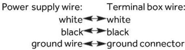
- Connect the wires as follows using UL listed wire nuts of the appropriate size to connect power cord to 16-gauge dishwasher wire.
Power supply wire: Terminal box wire:
white←→white
black←→black
ground wire↔ground connector
NOTES:
- Use cUL/UL listed wire nuts of the appropriate size to connect the power cord to 16-gauge dishwasher wiring.
- Insert wire ends in the wire nut. Do not pre-twist bare wire.
- Twist the wire nut.
- Gently tug on wires b be sure both wires are secured.

Ground

White

Black
- Tighten s train relief screws to secure the power cord.
- Gently guide the wire nuts into the junction box, and then replace the junction box cover making sure to not pinch the wires.
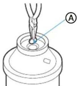
CONNECT TO WATER SUPPLY
IMPORTANT: Handle and reposition the copper tubing gently; it bends and kinks easily.
-
Connect the water supply line to the 90^ elbow.
-
Slide the nut onto copper tubing, approximately 1" (2.5 cm) from the end, and then slide the ferrule onto the tubing. Do not position the ferrule on the end of the tubing.
- Insert the copper tubing into the elbow as far as it will go.
- Slide the nut and ferrule forward, and then start threading the nut onto the elbow.
IMPORTANT: Do not solder within 6" (15.2 cm) of the water inlet valve.
Ⓐ Elbow
⑧ errule
© Compression Nut
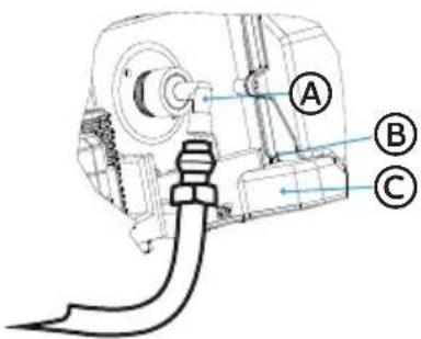
- Route the water supply line in the channel on the left-hand side of the base. To minimize the noise caused by vibration when using the dishwasher, make sure the supply line does not touch the dishwasher base, frame, or motor. Make sure the dishwasher is not resting on and/or pinching the supply line.
- Tighten the compression nut until snug. Do not overtighten.
- Place a paper towel under elbow, and then turn on the water supply to check for leaks.
-
Connect the drain hose to the waste tee or garbage disposal using one of the following methods.
-
Option 1 - Garbage Disposal - With Air Gap
- Option 2 - No Garbage Disposal- With Air Gap
- Option 3 - Garbage Disposal - No Air Gap*
- Option 4 - No Garbage Disposal - No Air Gap*
*an air gap is recommended
IMPORTANT:
• Always use a new drain hose when installing a new dishwasher.
- Total drain hose length must not exceed 10 ft (3.05 m), for proper drain operation.
- To minimize the noise caused by vibration when using the dishwasher, route the drain hose so that it avoids contact with the floor and the edge of the hole in the cabinet through which the hose passes.
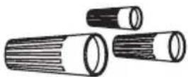
- The molded end of the drain hose will fit 58'' (1.6 cm), 34'' (1.9 cm) or 1" (2.5 cm) diameter connections on an air gap, waste tee or disposal. Cut on the marked line as required for your installation.
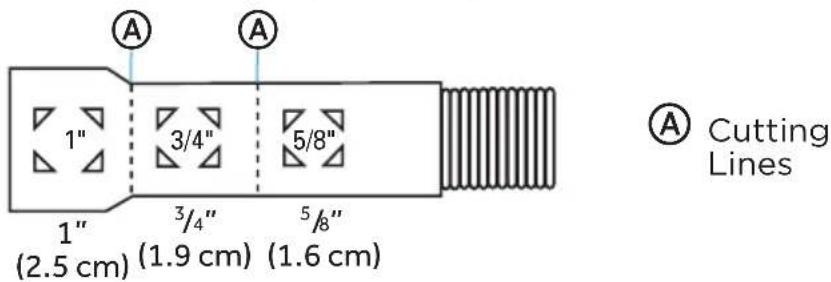
NOTE: Use 58 " or 78 " inside diameter hose and a coupler to connect the two hose ends. Secure the connection with hose clamps if an extension is required.
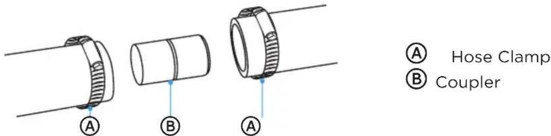
- Secure the drain hose to the air gap, waste tee or garbage disposal with clamps.
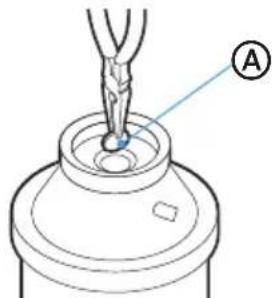
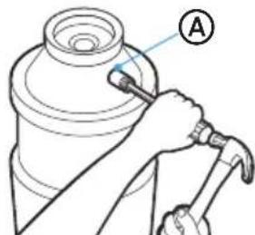
Option 1 - (Garbage Disposal - With Air Gap):
- Remove the knockout drain plug from the disposal inlet. Using a screwdriver and hammer, firmly tap the plug. The plug will separate and fall into the disposal.
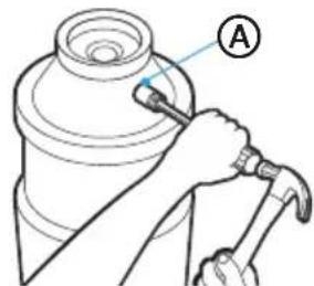
A
Disposal Inlet
- R emove the drain plug from the disposal.
A
Disposal Drain Plug
IMPORTANT: If you need to cut the drain hose to fit the diameter of the connection, cut only the rubber end of the hose, as shown earlier in this section (do not cut into the ridged section).
-
Using a screw-type clamp*, attach the drain hose to the air gap. Cut the rubber end of the hose, as needed.
-
Use a rubber hose connector * with a screw type clamp* to connect air gap to garbage disposal inlet.
NOTE: This connection must be located before the drain trap and at least 20" (50.8 cm) above the floor where dishwasher will be installed.
(A) Drain Hose - Cut Here if Needed
B Screw-Type Clamps
© Air Gap
(D) Screw-Type Clamp
E Drain Hose
⑤ Rubber Hose Connector
© Garbage Disposal Inlet
(H) Dain Trap
*Parts available from local plumbing supply store.
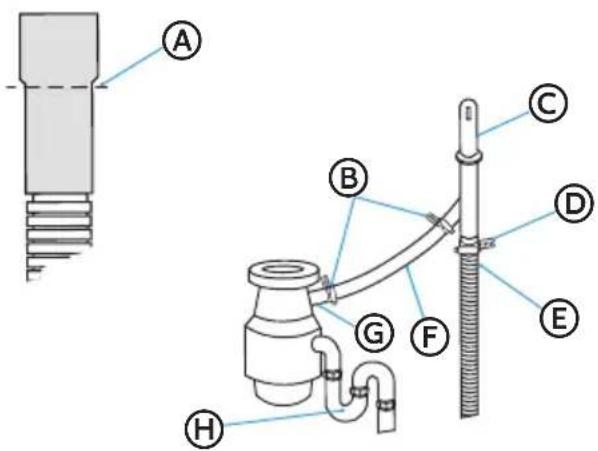
Option 2 - (No Garbage Disposal - With Air Gap):
IMPORTANT: If you need to cut the drain hose to fit the diameter of the connection, cut only the rubber end of the hose, as shown earlier in this section (do not cut into the ridged section).
- Attach drain hose to air gap with large screw-type clamp. Cut the rubber end of the drain hose, as needed.
- Use a rubber hose connector* with spring or screw type clamps* to connect air gap to garbage disposal inlet.
NOTE: This connection must be located before the drain trap and at least 20" (50.8 cm) above the floor where dishwasher will be installed.
(A) Drain Hose - Cut Here if Needed
B Screw-Type Clamps
© Air Gap
© Screw-Type Clamp
E Drain Hose
⑤ Rubber Hose Connector
© Waste Tee
H Drain ap
*Parts available from local plumbing supply store.
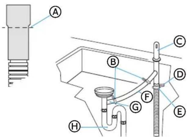
Option 3 - (Garbage Disposal - No Air Gap):
- Remove the knockout drain plug from the disposal inlet. Using a screwdriver and hammer, firmly tap the plug. The plug will separate and fall into the disposal.
A
Disposal Inlet
- R emove the drain plug from the disposal.
A
Disposal Drain Plug
IMPORTANT: If you need to cut the drain hose to fit the diameter of the connection, cut only the rubber end of the hose, as shown earlier in this section (do not cut into the ridged section).
- Using a screw-type clamp*, attach the drain hose to the garbage disposal inlet.
NOTES:
- This connection must be located before the drain trap and at least 20" (50.8 cm) above the floor where dishwasher will be installed.
- It is recommended that the drain hose be looped up and securely fastened to the underside of the counter at a minimum height of 32" (81.3 cm).
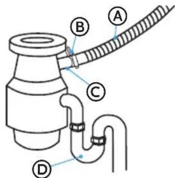
Ⓐ Drain Hose
⑧ Screw-Type Clamp
© Garbage Disposal Inlet
(D) Drain Trap
* Parts available from local plumbing supply store.
Option 4 - (No Garbage Disposal - No Air Gap):
IMPORTANT: If you need to cut the drain hose to fit the diameter of the connection, cut only the rubber end of the hose, as shown earlier in this section (do not cut into the ridged section).
- Attach drain hose to waste tee with 1 12 to 2 (3.8 to 5 ~cm ) screw-type clamp*.
NOTES:
- This connection must be located before the drain trap and at least 20" (50.8 cm) above the floor where dishwasher will be installed.
- It is recommended that the drain hose be looped up and securely fastened to the underside of the counter at a minimum height of 32" (81.3 cm).
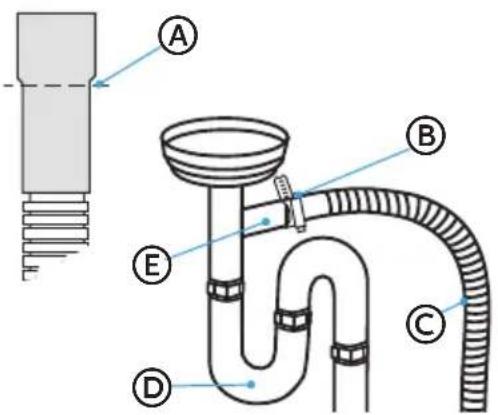
Ⓐ In Hose - Cut Here if Needed
(B) Screw-Type Clamps
© Drain Hose
(D) Drain Trap
E Waste Tee
*Parts available from local plumbing supply store.
SECURE DISHWASHER
To secure the dishwasher to either the Countertop (Method 1) or Cabinet (Method 2), follow the instructions for the method specific to your installation.
Method 1 - Installation to Countertop
Secure the dishwasher to the countertop using the two mounting clips installed to the top of the dishwasher.
- Open the dishwasher, remove the lower dish rack, and place a towel over the filters, located at the bottom of the tub, to prevent debris from falling into the pump system.
- Check that the dishwasher is level and centered side to side in the opening so there is no interference with adjacent cabinets when opening or closing the door.
-
Check that the tub flange aligns with the front face of the cabinet frame.
-
Using two Phillips-head screw (provided), fasten the two mounting clips on the top of the dishwasher to the underside of the countertop.
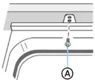
natural_image
Pure technical diagram of a pipe connection with no text, numbers, or symbolsⒶ #8 x 5/8" Phillips Flat-head Screw
-
Open the door about 3" (7.6 cm) and check that the space between the inner door and tub is equal on both sides.
-
If spacing is not equal, loosen the mounting clip screws and shift the tub. Retighten bracket screws.
-
Check that the top of the door does not contact the screws, mounting clips or countertop. If it does, the dishwasher must be lowered and leveled again. See "Level The Dishwasher."
NOTES
- Drive the screws straight and flush. Protruding screw heads will scratch the top of the control panel and can interfere with door closing.
-
If spacing is not equal, loosen the bracket screws and shift the tub. Retighten the bracket screws.
-
Remove towel from dishwasher.
-
Reinstall the lower dish rack.
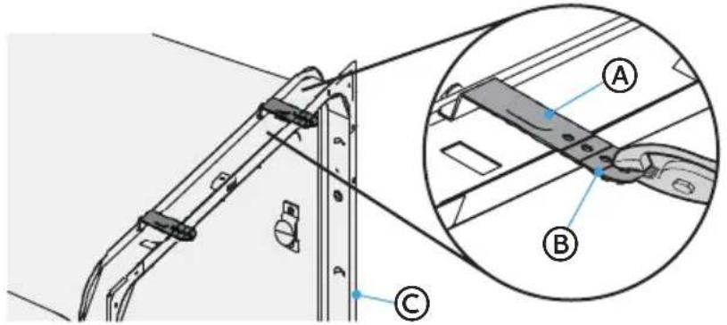
Method 2 - Installation to Adjacent Cabinets
Secure the dishwasher to the adjacent cabinets using the side mounting brackets.
-
Open the dishwasher, remove the lower dish rack, and place a towel over the filters, located at the bottom of the tub, to prevent debris from falling into the pump system.
-
Insert a mounting clip into the slot (one on each side) of the dishwasher.
natural_image
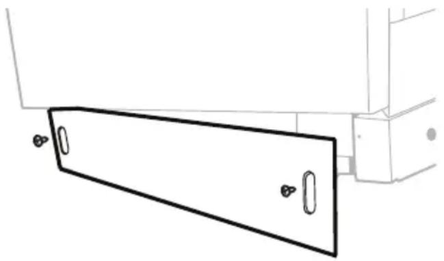
Pure technical line drawing of a mechanical bracket or lever assembly without any text, numbers, or symbols-
Open the dishwasher door. Using a flat-blade screwdriver or prying tool, remove the hole covers (one on each side).
-
Insert the screws through the dishwasher side-mount bracket and into the adjacent cabinet on each side.
-
Reinstall the hole covers.
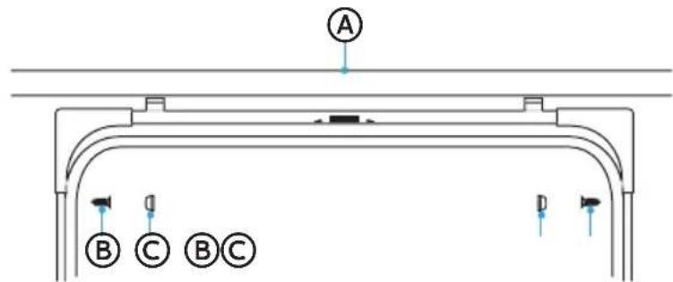
Ⓐ Granite Countertop
(B) Screw (C) Hole Cover
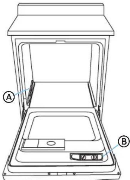
- Close dishwasher door and verify that gap between the countertop and the top of the dishwasher door is at least 14 " (0.64 cm).
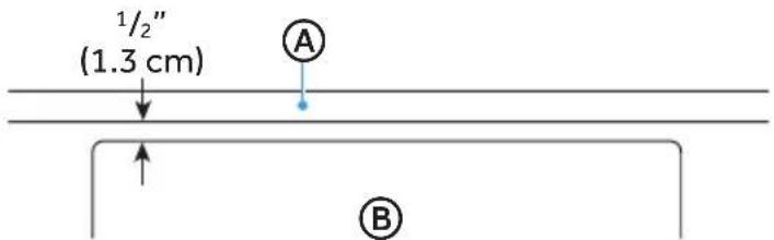
Ⓐ Countertop Ⓑ Dishwasher Door
-
R emove towel from dishwasher.
-
Reinstall the lower dish rack.
PRE-TEST CHECKLIST
- Check that the power is OFF.
- Check door opening and closing. If door does not open and close freely or tends to fall, check spring adjustments. See "Check Door Balance."
- Check that wiring is secure under the dishwasher, not pinched or in contact with door springs or other components. See "Position the Water Line and House Wiring."
- Check door alignment with tub. If door hits tub, level dishwasher. See "Level Dishwasher."
- Pull out the lower rack, about halfway. Check that the rack does not roll back into the dishwasher or forward onto the door. If the rack moves, adjust leveling legs. See "Level the Dishwasher."
- Check door alignment with cabinet. If door hits cabinet, reposition or level the dishwasher. See "Level the Dishwasher."
- Verify that the water supply and drain lines are not kinked or in contact with other components.
- Turn on the sink hot water faucet and verify water temperature. Incoming water temperature must be between 120^ F and 150^ F ( 49^ C and 65^ C). A minimum of 120^ F ( 49^ C) temperature is required for best wash performance.
- Add 2 quarts (1.9 L) of water to the bottom of the dishwasher to lubricate the pump seal.
- Turn on water supply. Check for leaks. Tighten connections if needed.
- Remove protective film, if present, from the control panel and door.
TEST DISHWASHER

WARNING

Electrical Shock Hazard
• Electrically ground dishwasher.
- Connect ground wire to green ground connector in terminal box.
If connecting with a power cord:
- Plug into a grounded 3-prong outlet.
- Do not use an adapter.
- Do not remove the ground prong from the power cord plug.
- Do not use an extension cord.
-
Failure to follow these instructions can result in death, fire, or electrical shock.
-
If using a direct wire cable, turn on power at source.
-
If using a power cord, plug cord into a grounded 3-prong outlet. Make sure the power cord does not touch the motor or the lower part of the dishwasher tub, and then turn on power at source.
-
Connect to power supply.
- On the Control Panel, press the controls needed to start the shortest cycle. See the User Manual for instructions.
- Firmly close the dishwasher door within 4 seconds of pressing START.
-
After the first 2 minutes, open the door. Check to see that there is water in the bottom of the dishwasher tub. If water has not entered the dishwasher, check that the water and power supplies are turned on.
-
Check for leaks under the dishw asher. If a leak is found, turn power and water supply off, then tighten connections. Restore power after leak is corrected.
- Check for leaks around the door. A leak around the door could be caused by door rubbing or hitting against adjacent cabinetry. Reposition the dishwasher, if necessary.
- When the dishwasher is draining, check the drain lines. If leaks are found, turn power off at the breaker and correct plumbing as necessary. Restore power after corrections are made.
- Open dishwasher door and make sure most of the water has drained. If not, check that disposal plug has been removed and/or air gap is not plugged. Also check drain line for kinking.
- Run the dishwasher through another fill and drain cycle. Check for leaks and correct, if needed.
REPLACE THE KICK PLATE
- Place the kick plat e against the legs of the dishwasher. The slots in the kick plate should align with the screw holes in the bracket. Allow the bottom edge of the kick plate to touch the floor.
- Using screws (provided), fasten the kickplate to the dishwasher.
natural_image
Pure technical line drawing of a mechanical component with no text or symbolsLave-vaisselle
natural_image
Exterior view of a stainless steel kitchen appliance (no visible text or symbols)SÉCURITÉ LIÉE AU LAVE-VAISSELLE ....3
CRITÈRES D'INSTALLATION ....5
Outils et pièces 5
natural_image
Simple black silhouette of a folded book or document with a bookmark, resting on a flat line (no text or symbols)natural_image
Line drawing of a handheld electric drill with multiple drill bits (no text or symbols)Perceuse et mèches
natural_image
Line drawing of a pair of pliers with no text or symbolsPince à dénuder
CONDITIONS D'EMPLACEMENT
IMPORTANT :
DIMENSION DU PRODUIT
CRITÈRE SUR LE DRAIN
natural_image
Technical diagram of a battery pack with internal components and a screwdriver, showing no text or symbolsnatural_image
Technical line drawing of a mechanical housing or enclosure with internal grid structure and labeled point A (no text or symbols beyond label)natural_image
Technical line drawing of a mechanical assembly with a spring and threaded component (no text or symbols)

Ⓐ Tube en cuivre
natural_image
Pure structural diagram of a rectangular frame with corner supports and mounting holes (no text or symbols)INSTALLER LES SUPPORTS DE MONTAGE
natural_image
Abstract black-and-white graphic of a folded paper or book with a diagonal line (no text or symbols)natural_image
Line drawing of a person kneeling beside a door handle, holding an open panel (no text or symbols)natural_image
Illustration of a person using a tool to avoid overpassing equipment, enclosed in a blue circle (no text or symbols)natural_image
Simple diagram with a blue arrow pointing to a small square (no text or symbols)natural_image
Technical diagram of a mechanical assembly with labeled component (A), showing internal components and no readable text or symbols.
Ⓐ Sol Ⓑ Blanc © Noir
Ⓐ Sol Ⓑ Blanc © Noir
CONNECTEZ LE CORDON D'ALIMENTATION

AVERTISSEMENT

natural_image
Simple diagram with a blue arrow pointing left and a small box labeled '0' at the bottom (no text or symbols within the diagram itself)natural_image
Technical diagram of a mechanical assembly with labeled component (A), showing internal components and alignment lines without any readable text or symbols.
Ⓐ Sol
B Blanc
© Noir
Ⓐ Elbow
B efrule
© Compression Nut

Lignes de coupe
natural_image
Pure technical diagram of a pipe connection with a labeled point A, no text or symbols present
natural_image
Pure technical line drawing of a mechanical component without any text, numbers, or symbolsnatural_image
Pure technical line drawing of a mechanical component with no text or symbolsLavavajillas
natural_image
Exterior view of a stainless steel multi-door厨柜 (no visible text or symbols)NÚMERO DE MODELO MDT24H14ASTC
www.midea.com
natural_image
Simple black-and-white icon of a folded book or notebook (no text or symbols)Peligro de vuelco
natural_image
Line drawing of a handheld electric drill with multiple drill bits (no text or symbols)natural_image
Line drawing of a pair of pliers with metal handles and jaw (no text or symbols)Alicate pelacables
DIMENSIONES DEL PRODUCTO

natural_image
Technical line drawing of a mechanical housing with internal components and a tool, no text or symbols presentⒶ Tornillos de la placa protectora (2)
natural_image
Technical line drawing of a mechanical housing or enclosure with internal grid structure and labeled point A (no text or symbols beyond label)natural_image
Technical line drawing of a mechanical assembly with a spring and threaded component (no text or symbols)Ⓐ Tubería de cobre
3" to 4 ^3/4 " (7.6 cm to 12.1 cm)
natural_image
Pure structural diagram of a rectangular beam supported by vertical supports (no text or symbols)natural_image
Simple black-and-white icon of a tilted book with a flat line underneath (no text or symbols)Peligro de vuelco
natural_image
Line drawing of a person kneeling beside a cabinet or enclosure (no text or symbols)natural_image
Illustration of a person using a laptop to stop a bicycle, no text or symbols presentnatural_image
Simple diagram with a blue arrow pointing left and a small box labeled '0' at the bottom (no text or symbols beyond basic labels)natural_image
Technical line drawing of a mechanical assembly with no visible text or symbols
Prensacable
Ⓐ Cable a tierra
B Blanco
© Negr
Ⓐ Cable a tierra
B Blanco
© Negro
natural_image
Simple diagram with a blue arrow pointing left and a black square labeled '0' at the bottom (no text or symbols beyond basic labels)natural_image
Technical diagram of a mechanical assembly with labeled component (A), showing internal components and alignment lines without any readable text or symbols.
Prensacable
natural_image
Three diagrams showing twisted cable structures with arrows indicating motion (no text or symbols)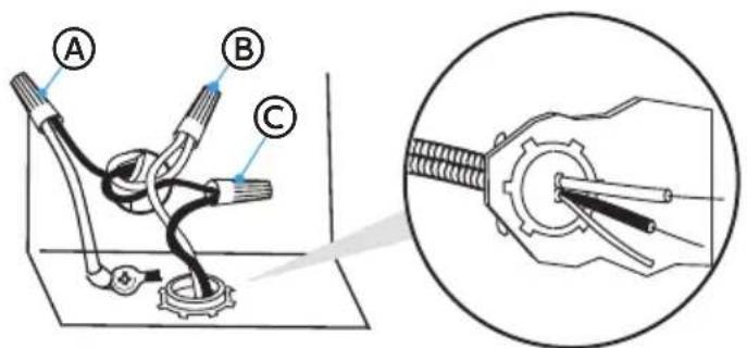
Ⓐ Cable a tierra
B Blanco
© Negro
Ⓐ Elbow
B efrule
© Compression Nut
natural_image
Technical line drawing of a mechanical assembly with no visible text or symbolsⒶ Líneas de corte
natural_image
Pure technical diagram of a pipe connection with a labeled point A, no text or symbols present(A) Destornillador plano Phillips nro. 8 x 5 / 8 in (1,6 cm)