GBC 64000 KB - Cooker TEKA - Free user manual and instructions
Find the device manual for free GBC 64000 KB TEKA in PDF.

User questions about GBC 64000 KB TEKA
0 question about this device. Answer the ones you know or ask your own.
Ask a new question about this device
Download the instructions for your Cooker in PDF format for free! Find your manual GBC 64000 KB - TEKA and take your electronic device back in hand. On this page are published all the documents necessary for the use of your device. GBC 64000 KB by TEKA.
USER MANUAL GBC 64000 KB TEKA
natural_image
Modern kitchen interior with dark wood cabinets and stainless steel ovens, featuring a 'TEKA' logo in the top right corner (no other text or symbols visible)User Manual
natural_image
Black gas stove with three burners and a central vent (no text or symbols visible)Resumen - Summary - Résumé - Περίληψη - Resumo

Pag 4 - 17 Installation, assembly, cleaning, maintenance and the various assembly phases. Technical data.
Pag. 29 Description, instructions for the installation and advice for the maintenance. Instructions Manual.

natural_image
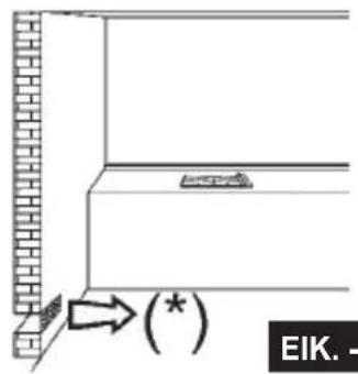
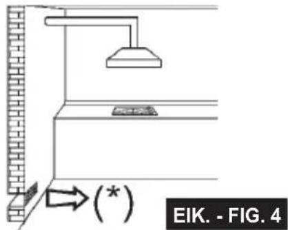
Line drawings of a two-wheeled cooking pot with a side-mounted heating element (no text or symbols)(*) entrada de aire: ver el capítulo de instalación (apartados 5 y 6)
(*) air inlet: see installation chapter (paragraphs 5 and 6)
(*) entree d'air: voir chapitre installation (paragraphes 5 et 6)
(*) εισοδος αερα: βλεπε κεφαλαιο τοποθετησης (παραγραφοι 5 και 6)
(*) entrada de ar de 100 cm2 de secção mínima (parágrafos 5 e 6)
text_image
EIK. -EIK. - FIG. 3
text_image
EIK. - FIG. 4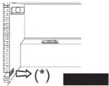
natural_image
Diagram showing a wall-mounted device with a brick wall and a rectangular component, connected to a wall-mounted unit (no text or symbols present)LIMPIEZA - CLEANING - NETTOYAGE ΚΑΘΑΡΙΣΜΑ - LIMPEZA
text_image
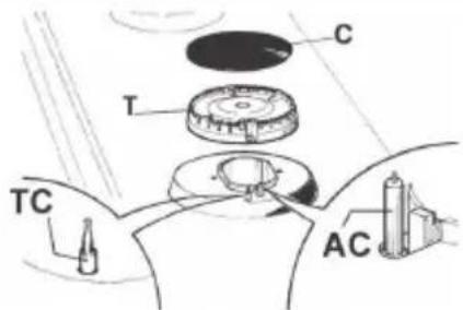
C T TC ACEIK. - FIG. 6
text_image
B A B A XFIG. 6/B
natural_image
Line drawing of a hand using a tool to clean or inspect a circular component (no text or symbols)
INSTALACIÓN - INSTALLATION - INSTALLATION ΕΓΚΑΤΑΣΤΑΣΗ - INSTALAÇÃO
text_image
C B D E A F Min. 70 mmEIK. - FIG. 7 EIK
text_image
Min. 650 mmFIG. 8/A
text_image
N C L
INSTALACIÓN - INSTALLATION - INSTALLATION ΕΓΚΑΤΑΣΤΑΣΗ - INSTALAÇÃO
| Modelos:Models:Modèles:Movtéλα:Modelos: | GBC 63010GBC 64000GBC 64001GBC 75030GBE 64000GBC 63110 | GBC 95030 | GBC 64002GBE 64002GBE 63012GBC 63012 | GBC 64003 GBC 32000 | |
| Referencia página | 6 - 8 7 - | 8 10 - 11 12 | - 13 14 | ||
| Reference page | 6 - 8 7 - | 8 10 - 11 12 | - 13 14 | ||
| Reference page | 6 - 8 7 - | 8 10 - 11 12 | - 13 14 | ||
| Avaφopá σελίδα | 6 - 8 7 - | 8 10 - 11 12 | - 13 14 | ||
| Referência página | 6 - 8 7 - | 8 10 - 11 12 | - 13 14 | ||
GBC 63010 - GBC 64000 - GBC 64001 - GBC 75030 GBE 64000 - GBC 63110
text_image
Technical diagram showing assembly of a device with labeled components and a magnified view of a bracket component.EIK. - FIG. 9
Ganchos Laterales cromada Hooks Lateral chrome Crochets Cote chrome γαντζουσ Πλευρικός χρώμιο Ganchos Lateral cromados
INSTALACIÓN - INSTALLATION - INSTALLATION ΕΓΚΑΤΑΣΤΑΣΗ - INSTALAÇÃO
GBC 95030
Ganchos Laterales cromada Hooks Lateral chrome Crochets Cote chrome γαντζουσ Πλευρικός χρώμιο Ganchos Lateral cromados
text_image
Technical diagram showing installation of a ceiling-mounted device with labeled components and an inset view of a bracket component.EIK. - FIG. 10/C
text_image
G F EIK. - FIG. 9/A EI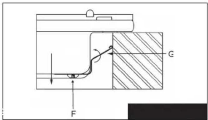
text_image
G FMONTAJ - INSTALLATION - INSTALARE INSTALACE - INŠTALÁCIA
text_image
Technical diagram showing a mechanical assembly with labeled components and directional arrows indicating motion or assembly.INSTALACIÓN -INSTALLATION - INSTALLATION ΕΓΚΑΤΑΣΤΑΣΗ - INSTALAÇÃO
GBE 64002
GBC 64002
GBE 63012
GBC 63012
text_image
G F G. 11EIK. - FIG. 11
INSTALACIÓN -INSTALLATION - INSTALLATION ΕΓΚΑΤΑΣΤΑΣΗ - INSTALAÇÃO
text_image
Technical diagram of an electronic device with labeled components and directional arrows indicating assembly or assembly.La instalación correcta de la placa de cocción Correct installation of the hob Installation correcte de la table de cuisson Σωστή εγκατάσταση της εστίας Instalação correta da placa
text_image
Technical diagram showing a heating or cooling system with labeled components and directional arrowstext_image
Technical diagram of a ceiling-mounted device with labeled components and directional arrows indicating assembly or installation.EIK. - FIG. 13
INSTALACIÓN -INSTALLATION - INSTALLATION ΕΓΚΑΤΑΣΤΑΣΗ - INSTALAÇÃO
natural_image
Isometric line drawing of a tray with four small objects inside, labeled with arrows 1 and 2 (no text or symbols on the objects)natural_image
Diagram of a mechanical device with labeled parts G and F (no text or symbols beyond labels)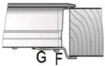
natural_image
Diagram of a wooden shelf with labeled parts G and F (no text or symbols beyond labels)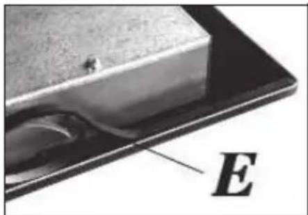
text_image
EEIK. - FIG. 15/A
natural_image
Close-up of a layered electronic component with labeled parts A and B, showing internal structure (no text or symbols beyond labels)EIK. - FIG. 15/B
EIK. - FIG. 15
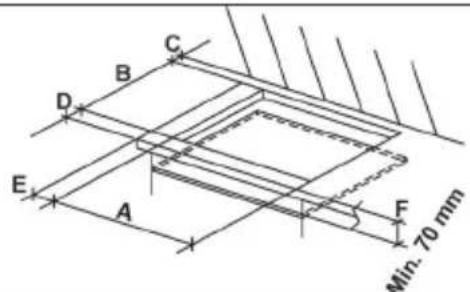
MEDIDAS QUE ES PRECISO RESPETAR (en mm) COMPLY WITH THE DIMENSIONS (in mm) DIMENSIONS A RESPECTER (en mm) MEΓΕΘΗ ΠΟΥ ΠΡΕΠΕΙ ΝΑ ΤΗΡΗΘΟΥΝ (σε mm) MEDIDAS A RESPEITAR (en mm)
| Mod: | TIPO/TYPE TYPNOΣ | A B C D E F | |||||
| GBE 64002GBC 63010GBC 64002GBC 64000GBC 64001GBC 75030GBE 64000GBE 63012GBC 63012GBC 63110 | A | 570 480 | 60 60 165 | 70 min. | |||
| GBC 64003 | A | 575 405 | 97,5 97,5 | 162,5 70 min. | |||
| GBC 32000 | B | 280 490 | 55 55 160 | 70 min. | |||
| GBC 95030 | A | 850 490 | 55 55 73.5 | 70 min. | |||
REGULACIONES - INSTALLATION - REGLAGES KANONIŠMOŠ - REGULAÇÕES
text_image
D C MEIK. - FIG. 16 EIK
text_image
D C M
TRANSFORMACIONES - CONVERSIONS - TRANSFORMATIONS METATPOΠΕΣ - TRANSFORMAÇÕES
text_image
Technical diagram showing a mechanical assembly with labeled parts A and B, likely illustrating a tool or component setup.EIK. - FIG. 17

natural_image
Close-up of a mechanical component with a central hub and internal structure (no visible text or symbols)EIK. - FIG. 17/A
natural_image
Simple line drawing of a curved pipe or tube with a base and a labeled point B (no text or symbols)EIK. - FIG. 18
DADOS TÉCNICOS RELATIVOS À REGULAÇÃO DE GÁS DO APARELHO
TECHNICAL DATA FOR THE APPLIANCE GAS REGULATION
DONNEES TECHNIQUES DE LA RÉGULATION GAZ DE L'APPAREIL
In case of adaptation of the hob to another type of gas, operate as described in the directions for the and installation use and replace the label on the bottom with the one provided in the spare bag.
natural_image
Pure electrical circuit lines without any symbolsnatural_image
Simple line drawing of a bag with a handle and decorative elements (no text or symbols)Children less than 8 years of age shall be kept away unless continuously supervised.
This appliance can be used by children aged from 8 years and above and persons with reduced physical, sensory or mental capabilities or lack of experience and knowledge if they have been given supervision or instruction concerning use of the appliance in a safe way and understand the hazards involved. Children shall not play with the appliance.
Cleaning and user maintenance shall not be made by children without supervision.
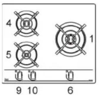
DESCRIPTION OF HOBS
1 Ultra rapid gas burner of 3500 W
2 Rapid gas burner of 2800 W
3 Semirapid gas burner reduced of 1400 W
4 Semirapid gas burner of 1750 W
5 Auxiliary gas burner of 1000 W
6 Burner n° 1 control kno
7 Burner n° 2 control knob
8 Burner n°3 control knob
9 Burner n° 4 control knob
10 Burner n° 5 control knob
Attention: this appliance has been manufactured for domestic use only and it employment by private person.
This cook top was designed to be used exclusively as a cooking appliance: any other use (such as heating rooms) is to be considered improper and dangerous.
text_image
4 5 1 9 10 6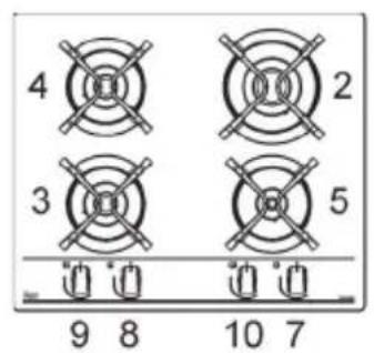
text_image
4 2 3 5 9 8 10 7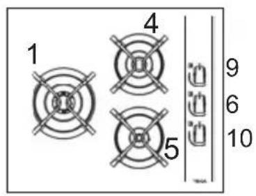
text_image
1 4 9 6 10 5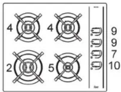
text_image
4 4 2 5 9 9 7 10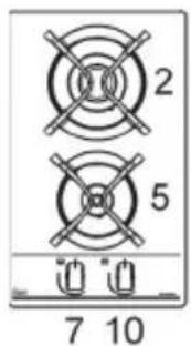
text_image
2 5 7 10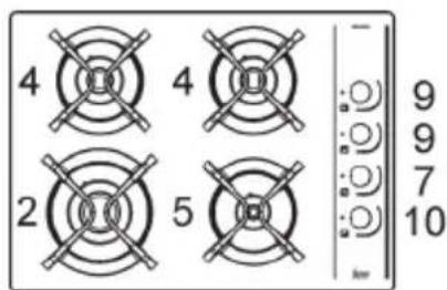
text_image
4 4 2 5 - 9 9 7 10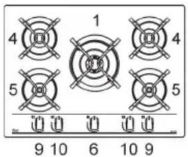
text_image
4 1 4 5 5 9 10 6 10 9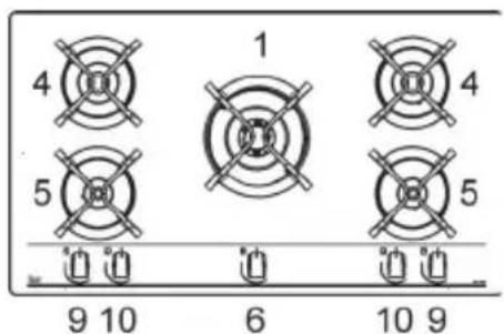
text_image
4 1 4 5 5 9 10 6 10 9IMPORTANT SAFETY WARNINGS

IMPORTANT WARNINGS FOR THE USER
During operation the work surfaces of the cooking area become very hot: keep children away!
CAUTION:
In case of hotplate glass breakage:
- shut immediately off all burners and any electrical heating element and isolate the appliance from the power supply;
- do not touch the appliance surface;
- do not use the appliance.
- IMPORTANT!
A perfect installation, adjustment or transformation of the cook top to use other gases requires a QUALIFIED INSTALLER: a failure to follow this rule will void the warranty.
- IMPORTANT: the appliance must be installed following the manufacturer's instructions. The manufacturer will not be liable for injury to persons or animals or property damage caused by an incorrect installation.
- If the installation requires modifications to the home's electrical system or if the socket is incompatible with the appliance's plug, have changes or replacements performed by professionally-qualified person. In particular, this person must also make sure that the section of the wires of the socket is suitable for the power absorbed by the appliance.
- Use of a gas cooking appliance produces heat and moisture in the room in which it is installed. The room must therefore be well ventilated by keeping the natural air vents clear (see fig. 3) and by activating the mechanical aeration device (suction hood or electric fan fig. 4 and fig. 5).
- Intensive and lengthy use of the appliance may require additional ventilation. This can be achieved by opening a window or by increasing the power of the mechanical exhausting system if installed.
- Do not attempt to change the technical characteristics of the product because it can be dangerous.
- If you should not to use this appliance any more (or replace an old model), before disposing of it, make it inoperative in conformity with current law on the protection of health and the prevention of environmental pollution by making its dangerous parts harmless, especially for children who might play on an abandoned appliance.
•CAUTION:
Do not touch the appliance with wet or damp hands or feet. Do not use the appliance barefoot
- The manufacturer will not be liable for any damage resulting from improper, incorrect or unreasonable use.
- During, and immediately after operation, some parts of the cook top are very hot: avoid touching them.
- After using the cook top, make sure that the knob is in the closed position and close the main tap of the gas supply or gas cylinder.
- If the gas taps are not operating correctly, call the Service Department.
- Keep the Warranty Certificate or the sheet of technical data with the Instructions Handbook during the appliance life. It contains important technical data.
IMPORTANT:
All our products are conform with the European Norms and relative amendments. The product is therefore conform with the requirements of the European Directivesin force relating to:
- compatibility electromagnetic (EMC);
- electrical security (LVD);
- restriction of use of certain hazardous substances (RoHS);
- EcoDesign (ERP).
The appliance complies with the provisions of the sub-regulations for European Directives:
- Regulation (EU) 2016/426.
USE
1) BURNERS
diagram is screen-printed above each knob on the front panel. This diagram indicates to which burner the knob in question corresponds. After having opened the gas mains or gas bottle tap, light the burners as described below:
- automatic electrical ignition
Push and turn the knob corresponding to the required burner in an anticlockwise direction until it reaches the full on position (large flame fig. 1), then depress the knob.
- Lighting burners equipped with flame failure device
The knobs of burners equipped with flame failure device must be turned in an anticlockwise direction until they reach the full on position (large flame fig. 1) and come to a stop. Now depress the knob in question and repeat the previously indicated operations.
Keep the knob depressed for about 10 seconds once the burner has ignited.
As far as the models equipped with the griddle are concerned, do not keep the ignition system activated for more than 15 seconds; if after 15 seconds the burner is not switched on jet, switch off the ignition and wait for at least 1 minute before trying again.
With regards to all the models, in case of accidental extinguishment of the flame, disengage the ignition by rotating the knob to the off position. Wait at least 1 minute before re-igniting the flame.
HOW TO USE THE BURNERS
Bear in mind the following indications in order to achieve maximum efficiency with the least possible gas consumption:
- use adequate pans for each burner (consult the following table and fig. 2).
- When the pan comes to the boil, set the knob to the reduced rate position (small flame fig. 1).
- Always place a lid on the pans.
- Use only pan with a flat bottom.
Burners Pan ∅ in cm
| Ultrarapid | 24 ÷ 26 |
| Rapid | 20 ÷ 22 |
| Semirapid reduced | 16 ÷ 18 |
| Semirapid | 16 ÷ 18 |
| Auxiliary | 10 ÷ 14 |
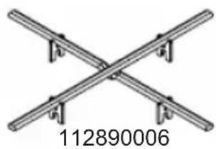
To accommodate large pans, such as paella pans or soup pots with a bottom diameter of 260mm, simply place the cross-shaped accessory onto the grid of your gas hob.
natural_image
Pure electrical circuit lines without any symbolsFor wok cast iron grid.
WARNINGS:
- burners with flame failure device may only be ignited when the relative knob has been set to the Full on position (fig. 1).
- Matches can be used to ignite the burners in a blackout.
- Never leave the appliance unattended when the burners are being used. Make sure there are no children in the near vicinity. Particularly make sure that the pan handles are correctly positioned and keep a check on foods requiring oil and grease to cook since these products can easily catch fire.
- Never use aerosols near the appliance when it is operating.
- Containers wider than the unit are not recommended.
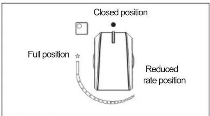
text_image
Closed position Full position Reduced rate positionFIG. 1
IMPORTANT:
always disconnect the appliance from the gas and electricity mains before carrying out any cleaning operation.
2) HOT PLATE
It is very important to clean the surface soon after every use, when the glass is still tepid.
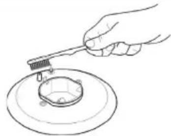
Periodically wash the hot plate, the enamelled stell pan support, the enamelled burner caps "A", "B" and "C" and the burner heads "T" (see fig. 6 - 6/A) with lukewarm soapy water. They should also be cleaned plugs "AC" and flame detection "TC" (see fig. 6). Clean them gently with a small nylon brush as shown (see fig. 6/B) and allow to dry fully.
Do not wash in the dishwasher.
Do not allow vinegar, coffee, milk, salted water, lemon or tomato juice from remaining in contact with the enamelled surfaces for long periods of time.
Do not use metallic sponges, powder abrasives or corrosive sprays.
WARNINGS:
comply with the following instructions, before remounting the parts:
- check that burner heads slots (see fig. 6-6/A) have not become clogged by foreign bodies.
- Check that enamelled burner cap "A - B - C" (fig. 6 - 6/A) have correctly positioned on the burner head. It must be steady.
- For an exact stability of the pan supports, verify that they are inserted in their specific centering niches situated on flanges.
- Do not force the taps if they are difficult open or close. Contact the technical assistance service for repairs.
- Don't use steam jets for the equipment cleaning.
- Do not wash enamel parts in dishwasher. Put them inside hot water for a while, clean with a soft cleaner and dry with a soft cloth or towel.
TECHNICAL INFORMATION FOR THE INSTALLER
Installation, adjustments of controls and maintenance must only be carried out by a qualified engineer.
The appliance must be correctly installed in conformity with current law and the manufacturer's instructions.
Incorrect installation may cause damage to persons, animals or property for which the Manufacturer shall not be considered responsible.
During the life of the system, the automatic safety or regulating devices on the appliance may only be modified by the manufacturer or by his duly authorized dealer.
3) INSTALLING THE HOT PLATE
Check that the appliance is in a good condition after having removed the outer packaging and internal wrappings from around the various loose parts. In case of doubt, do not use the appliance and contact qualified personnel.
Never leave the packaging materials (cardboard, bags, polystyrene foam, nails, etc.) within children's reach since they could become potential sources of danger.
The measurements of the opening made in the top of the modular cabinet and into which the hot plate will be installed are indicated in either fig. 7. Always comply with the measurements given for the hole into which the appliance will be recessed (see fig. 7 and 8).
The appliance belongs to class 3 and is therefore subject to all the provisions established by the provisions governing such appliances.
Note: continuous use could cause the burners to change colour due to the high temperature.
INSTALLATION
4) FIXING THE HOT PLATE
The hot plate has a special seal which prevents liquid from infiltrating into the cabinet. Strictly comply with the following instructions in order to correctly apply this seal:
- take off all the movable parts of the hob.
- Cut the seal in 4 parts of the necessary lenght to positioning it on the 4 edges of the crystal.
- Overturn the hot plate and correctly position seal "E" (fig. 15/A) under the edge of the hot plate itself, so that the outer side of the seal perfectly matches the outer perimetral edge of the crystal. The ends of the strips must fit together without overlapping.
- Evenly and securely fix the seal to the crystal, pressing it in place with the fingers.
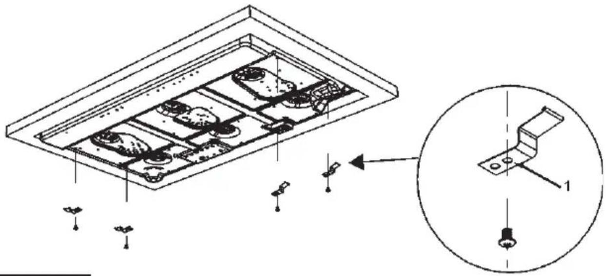
FIXING HOOKS
Phase 1
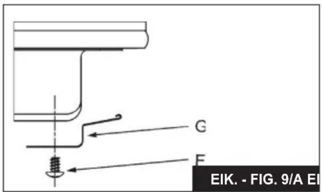
- Place the hooks chrome in their respective positions, use the hole no. 1 as reference for position lateral (fig. 9 - 10/C - 11 - 13), depending on the model;
- secure hooks "G" by means of screws "F" (fig. 9/A for lateral).
Phase 2
- Place the hooks black use the hole no. 2 for positions rear (fig. 10 - 10/D - 12 - 14), depending on the model.
- Secure hooks "G" by means of screws "F" (fig. 10/A for rear).
Phase 3
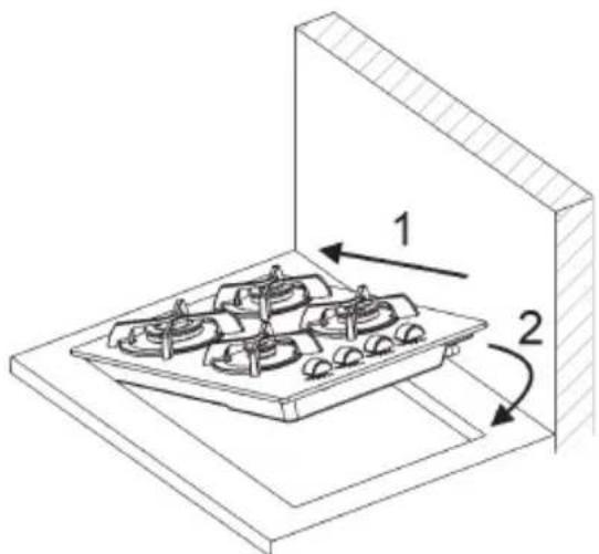
- Insert the cooking hob in the hole of the kitchen cabinet (direction 1), exerting a slight downward pressure (2) by exercising a certain level of force in order to get over the resistance of the hooks (fig. 9/B for lateral and fig. 10/B for rear).
- In order to avoid accidental touch with the overheating bottom of the hob, during the working, is necessary to put a wooden insert, fixed by screws, at a minimum distance of 70 mm from the top (see fig. 7).
Model: GBC 32000
- Position the hob in the hole in the unit and fasten it in place using the appropriate screws "F" of the fastening hooks "G" (see fig. 15).
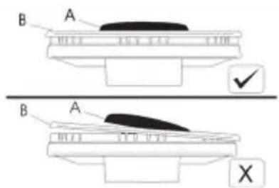
CAUTION: do not place the glass directly on the unit. The bottom of the hob must rest on the unit.
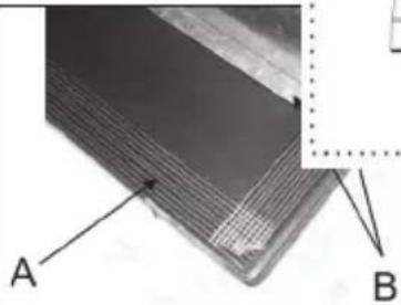
Caution: Do not allow the glass (A) lay directly on the work top. it is the metal bottom "carter" (B) that has to be in touch with the work top (see fig. 15/B).
INSTALLATION
IMPORTANT INSTALLATION INSTRUCTIONS
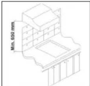
The installer should note that the appliance that side walls should be no higher than the hot plate itself. Furthermore, the rear wall, the surfaces surrounding and adjacent to the appliance must be able to withstand an temperature of 90 °C.
The adhesive used to stick the plastic laminate to the cabinet must be able to withstand a temperature of not less than 150 °C otherwise the laminate could come unstuck.
The appliance must be installed in compliance with BS 6172 1990, BS 5440 part. 2 1989 and BS 6891 1988.
This appliance is not connected to a device able to dispose of the combustion fumes. It must therefore be connected in compliance with the above mentioned installation standards. Particular care should be paid to the following provisions governing ventilation and aeration.
5) ROOM VENTILATION
To ensure correct operation of the appliance, it is important to ensure that the room where the hot plate is installed has sufficient ventilation, as set out in BS 5440 part 2. 1989. See table below.
| Type of appliance | Volume of room cubic metres | Min. size of vent sq. cm. | Openable window or alternative method of venting to the outside |
| Domestic ovens hotplates or any combinations | 5 | 100 | yes |
| 5 to 10 | 50 | yes | |
| 11 to 20 | nil | yes | |
| 20 and above | nil | yes |
Natural air flow must enter directly through permanent openings in the walls of the room in question. These must open towards the outside and possess a minimum section of 100 cm^2 see fig. 3). It must be impossible to obstruct these openings.
Indirect ventilation with air drawn from adjacent rooms is permitted in strict compliance with the provisions in force.
6) LOCATION AND AERATION
Gas cooking appliances must always dispose of their combustion fumes through hoods. These must be connected to flues, chimneys or straight outside (see fig. 4). If it is not possible to install a hood, an electric fan can be installed on a window or on a wall facing
outside (see fig. 5). This must be activated at the same time as the appliance, so long as the specifications in the provisions in force are strictly complied with.
7) GAS CONNECTION
Before connecting the appliance, check that the values on the data label affixed to the underside of the hot plate correspond to those of the gas mains in the home.
A label on the appliance indicates the regulating conditions: type of gas and working pressure.
WARNING:
a gas hot plate can only be connected by a CORGI Registered engineer.
Installations should be carried out in accordance with BS 6891 1988 and must comply with the Gas Safety Regulations.
All hot plate installations must include an isolation tap.
GAS PRESSURE TEST
Some hot plates models have a test point fitted under the control panel, to conduct a gas pressure test proceed as follows:
- turn off the gas supply.
- Remove screw in the pressure test point, place test gauge connecting tube on test point.
- Fit a burner ring and cap onto burner assembly, replace control knob onto corresponding control tap for the burner.
- Turn on gas and ascertain working pressure.
After test, turn off control tap, turn off gas supply, disconnect test gauge connecting tube.
Replace the test point screw, turn gas back on and test for soundness. Reassemble the hotplate.
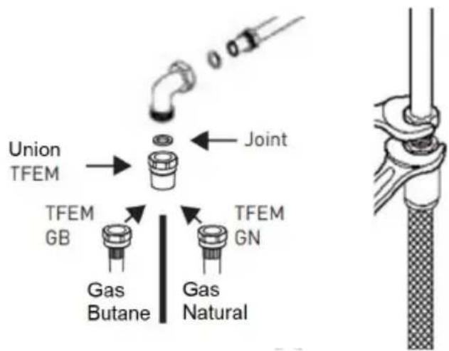
text_image
Union TFEM Joint TFEM GB Gas Butane Gas Natural TFEM GNINSTALLATION
The electrical connections of the appliance must be carried out in compliance with the provisions and standards in force.
Before connecting the appliance, check that:
- the voltage matches the value shown on the specification plate and the section of the wires of the electrical system can support the load, which is also indicated on the specification plate.
- The electrical capacity of the mains supply and current sockets suit the maximum power rating of the appliance (consult the data label applied to the underside of the hot plate).
- The socket or system has an efficient earth connection in compliance with the provisions and standards in force. The manufacturer declines all responsibility for failing to comply with these provisions.
When the appliance is connected to the electricity main by a socket:
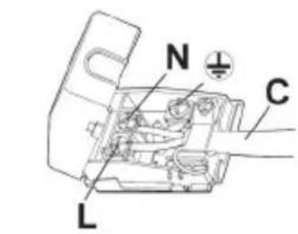
- fit a standard plug "C" suited to the load indicated on the data label to the cable. Fit the wires following figure 8/A, taking care of respecting the following correspondences:
Letter L (live) = brown wire;
Letter N (neutral) = blue wire;
earth symbol = green - yellow wire.
- The power supply cable must be positioned so that no part of it is able to reach an temperature of 90^ C.
- Never use reductions, adapters of shunts for connection since these could create false contacts and lead to dangerous overheating.
- The outlet must be accessible after the built-in.
When the appliance is connected straight to the electricity main:
- install an omnipolar circuit-breaker between the appliance and the electricity main. This circuit-breaker should be sized, in compliance with current installation regulations.
- Remember that the earth wire must not be interrupted by the circuit-breaker.
- For optimum safety, the electrical connection may also be protected by a high sensitivity differential circuit-breaker.
You are strongly advised to fix the relative yellow-green earth wire to an efficient earthing system.
Before performing any service on the electrical part of the appliance, it must absolutely be disconnected from the electrical network.
TEKA will not be liable for any damage caused by the alteration or modification of the product or its components during the installation. The installer will be liable for any damages or faults occurred for the incorrect assembly or installation. For any damages resulting from the installation of the product, please contact the authorized installer.
REGULATION
Always disconnect the appliance from the electricity main before making any adjustments. All seals must be replaced by the technician at the end of any adjustments or regulations.
Our burners do not require primary air adjustment.
9) TAPS
"Reduced rate" adjustment
- Switch on the burner and turn the relative knob to the "Reduced rate" position (small flame fig. 1).
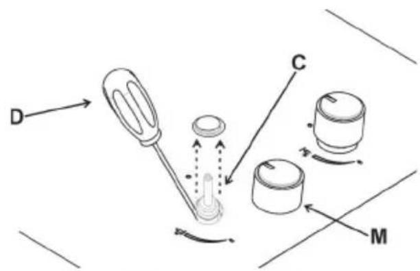
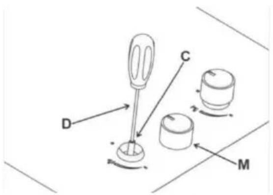
- Remove knob "M" (fig. 16 and 16/A) of the tap, which is simply pressed on to its rod. The by-pass for minimal rate regulation can be: beside the tap (fig. 16) or inside the shaft. In any case, to access to regulation, it can be done trough the insertion of a small screwdriver "D" beside the tap (fig. 16) or in the hole "C" inside the shaft of the tap (fig 16/A). Turn the throttle screw to the right or left until the burner flame has been adequately regulated to the "Reduced rate" position.
The flame should not be too low: the lowest small flame should be continuous and steady. Re-assemble the several components.
It is understood that only burners operating with G20 gas should be subjected to the above mentioned adjustments. The screw must be fully locked when the burners operate with G30 or G31 (turn clockwise).
TAPS LUBRIFICATION
Should a tap being blocked, do not force and ask for Technical Assistance.
CONVERSIONS
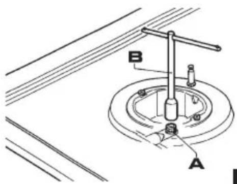
10) REPLACING THE INJECTORS
The burners can be adapted to different types of gas by mounting injectors suited to the type of gas in question. To do this, first remove the burner tops using a an appropriate tool. Now unscrew injector (see fig. 17 - 17/A) and fit a injector corresponding to the utilized type of gas in its place.
It is advisable to strongly tighten the injector in place.
After the injectors have been replaced, the burners must be regulated as explained in paragraphs 9. The technician must reset any seals on the regulating or pre-regulating devices.
The envelope with the injectors and the labels can be included in the kit, or at disposal to the authorized customer Service Centre.
For the sake of convenience, the nominal rate table also lists the heat inputs of the burners, the diameter of the injectors and the working pressures of the various types of gas.
TABLE
| BURNERS | GAS | NORMAL PRESSURE mbar | NORMAL RATE | INJECTOR DIAMETER MAX10Emm | NOMINAL HEAT INPUT (W) | ||||
| N° | DESCRIPTION | gr/h | l/h Min. | Gas Bumer* | |||||
| 1 | ULTRA RAPID (Version 3.5 kW) | G30 - BUTANG31 - PROPANG20 - NATURAL | 28 - 303720 | 254250 | 333 | 96 S496 S4145 H3 | 180018001800 | 350035003500 | 59,4 % |
| 2 | RAPID | G30 - BUTANG31 - PROPANG20 - NATURAL | 28 - 303720 | 204200 | 267 | 8383117 S | 900900900 | 280028002800 | 62,5 % |
| 3 | SEMIRAPID REDUCED | G30 - BUTANG31 - PROPANG20 - NATURAL | 28 - 303720 | 102100 | 133 | 606088 Z | 550550550 | 140014001400 | 64,7 % |
| 4 | SEMIRAPID | G30 - BUTANG31 - PROPANG20 - NATURAL | 28 - 303720 | 127125 | 167 | 656597 Z | 550550550 | 175017501750 | 61,1 % |
| 5 | AUXILIARY | G30 - BUTANG31 - PROPANG20 - NATURAL | 28 - 303720 | 7371 | 95 | 505072 X | 450450450 | 100010001000 | N.A. |
*In accordance with Regulation No. 66/2014 EU measures for the implementation of Directive 2009/125/EC, the performance (EEgas burner) was calculated according to EN 30-2-1 last review with the G20.
SERVICING
CABLE TYPES AND SECTIONS
| TYPE OF TYPE OF SINGLE - PHASE HOT PLATE CABLE POWER SUPPLY | |
| Gas hot plate H05 RR-F Section 3 x 0.75 mm | 2 |
ATTENTION!!!
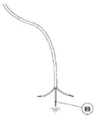
If the power supply cable is replaced, the installer should leave the ground wire (B) longer than the phase conductors (fig. 18) and comply with the recommendations given in paragraph 8.
WARNING: MAINTENANCE MUST ONLY BE PERFORMED BY AUTHORISED PERSONS.

In case of failure or cut in the cable, please move away from the cable and do not touch it. Moreover the device must be unplugged and not switched on. Call the nearest authorized service center to fix the problem.
TROUBLESHOOTING TABLE
FOR USERS
| ProblemsCausesSolutions | ||
| The gas ring burns unevenly | Burner crown maybe occluded by dirtyWrong gas regulation | Clean the burner crown with metal cleaning agentCall the assistance |
| Burner flame suddenly changes Incorrect burner components assembly | Assembly the burner components correctly | |
| Ignition of burners takes excessively long Incorrect burner components assembly | Assembly the burner components correctly | |
| The flame goes off after ignition | Early release of knob. Knob is not pushed in firmlyUncorrect pan dimensionThermocouple problems | Keep the knob pressed longer. Before releasing the knob, give it one final solid pushIf the flame goes out with a pan larger than those indicated in the booklet, the user must use the appropriate "paellero" gridMove the thermocoupleCall the assistance |
| The colour of the pan support has changed | Normal situation, caused by the high temperature | Clean the pan support with metal cleaning agents |
| The burner fails to ignite after pressing the knob (the spark-plug emit the spark) | Lack of gas or dirty on spark-plug Clean the spark-plug like described in the cleaning chapter on instruction manual | |
| The burner fails to ignite after pressing the knob (the spark-plug do not emit the spark) | Spark-plug or ignition generator problems | Call the assistance |
| The ignition generator does not work | Lack of electricityIncorrect ignition generator assembly or break | Check that the plug is inserted. Verify that the counter is turned on.Call the assistance |
| The spark-plug emit continuously the spark | HumidityIncorrect micro-switch assembly or break | Remove the power for 24 hours and allow the top to dry; verify that all the bushings are mounted correctlyCall the assistance |
TECHNICAL ASSISTANCE AND SPARE PARTS
Before leaving the factory, this appliance will have been tested and regulated by expert and specialized personnel in order to guarantee the best performances.
Any repairs or adjustments which may be subsequently required may only be carried out by qualified personnel with the utmost care and attention.
For this reason, always contact your Dealer or our nearest After Sales Service Center whenever repairs or adjustments are required, specifying the type of fault and the model of the appliance in your possession.
Please also note that genuine spare parts are only available from our After Sales Service Centers and authorized retail outlets.
The above data are printed on the data label put on the inferior part of the appliance and on the packing label.
The above informations give to the technical assistant the possibility to get fit spare parts and a heaven-sent intervention. We suggest to fill the table below.
MARK:
MODEL:
SERIES:
Keep the Warranty Certificate or the sheet of technical data with the Instructions Handbook during the appliance life. It contains important technical data.
This appliance is marked according to the European directive 2002/96/EC on Waste Electrical and Electronic Equipment (WEEE).
This guideline is the frame of a European-wide validity of return and recycling on Waste Electrical and Electronic Equipment.
MATIERES:
Pag. 41 DESCRIPTION DE TABLE DE CUISSON
Pag. 42 AVERTISSEMENTS DE SÉCURITÉ IMPORTANTS
Pag. 43 UTILISATION
Pag. 44 NETTOYAGE - INSTALLATION
Pag. 45 INSTALLATION, FIXATION DE LA TABLE DE CUISSON
Pag. 46 INSTALLATION
Pag. 47 INSTALLATION, BRANCHEMENT ELETRIQUE, REGLAGE ROBINETS
Pag. 48 TRANSFORMATION
Pag. 49 ENTRETIEN
Pag. 50 SERVICE APRES-VENTE
AVERTISSEMENT:
text_image
Union TFEM → Joint TFEM GB Gas Butane Gas Natural TFEM GNINSTALLATION
ROBINETS LUBRIFICATION
10) REMPLACEMENT DES BUSES
natural_image
Simple line drawing of a trash bin with two crossed x-axes (no text or symbols)FR
natural_image
Pure electrical circuit lines without any symbolsnatural_image
Pure electrical circuit lines without any symbolsPara grade de ferro fundido wok.
ADVERTÊNCIAS:
Country Subsidiary Address City Phone
| AustriaKüppersbusch Austria | Eitnergasse, 13 | 1231 Wien | +43 18 668 022 |
| BelgiumKüppersbusch Belgium S.P.R.L. | Doomveld Industrie, Asse 3, No. 11 - Boite 7 | 1731 Zellik | +32 24 668 740 |
| BulgariaTeka Bulgaria EOOD | Blvd. “Tsarigradsko Shosse” 135 | 1784 Sofia | +359 29 768 330 |
| ChileTeka Chi le S.A. | Avd El Retiro Parque los Maitenes, 1237. Parque Enea | Pudahuel, Santiago de Chile | + 56 24 386 000 |
| ChinaTeka International Trading (Shanghai) Co. Ltd. | No.1506, Shengyuan Henghua Bldg. No.200 Wending Rd. | Xuhui, Dist. 200030 Shanghai | +86 2 153 076 996 |
| Czech RepublicTeka CZ S.R.O. | V Holesovickách, 593 | 182 00 Praha 8 - Liben | +420 284 691 940 |
| EcuadorTeka Ecuador S.A. | Parque Ind. California 2, Via a Daule Km 12 | Guayaquil | +593 42 100 311 |
| FranceTeka France | 30 rue Maubec 33000 | Bordeaux | + 05 57 80 60 03 |
| GreeceTeka Hellas A.E. | Thesi Roupaki - Aspropyrgos | 193 00 Athens | +30 2 109 760 283 |
| HungaryTeka Magyarország Zrt. | Terv u. 92 | 9200 Mosonmagyaróvár | +36 96 574 500 |
| IndonesiaPT Teka Buana | Jalan Menteng Raya, Kantor Taman A9 Unit A3 | 12950 Jakarta | +62 215 762 272 |
| MalaysiaTeka Küchentechnik (Malaysia) Sdn Bhd | 10 Jalan Kartunis U1/47, Temasya Park, Off Glenmarie | 40150 Shah Alam, Selangor Darul Ehsan | +60 376 201 600 |
| MexicoTeka Mexicana S.A. de C.V. | Blvd Manuel A. Camacho 126, Piso 3 Col. Chapultepec | 11000 Mexico D.F. | +52 5 551 330 493 |
| MoroccoTeka Maro c S.A. | 73, Bd. Slimane, Depôt 33, Route de Ain Sebaa | Casablanca | +212 22 674 462 |
| PeruTeka Küchentechnik Perú S.A. | Av. El Polo 670 local A 201, CC El polo, Surco | Lima | +51 14 363 078 |
| PolandTeka Polska Sp. ZO.O. | ul. 3-go Maja 8 / A2 | 05-800 Pruszkow | +48 227 383 270 |
| PortugalTeka Portugal S.A. | Estrada da Mota - Apdo 533 | 3834-909 Ilhavo, Aveiro | +35 1 234 329 500 |
| RomaniaS.C. Teka Küchentechnik Romania S.R.L. | Sevastopol str., no 24, 5th floor, of. 15 | 010992 Bucharest Sector 1 | +40 212 334 450 |
| Russia/PocciaTeka Rus LLC/OOO "Teka Pyc" | Neverovskogo 9, Office 417, 121170, Moscow, Russia | 121087 Россия, Москва | +7 4 956 450 064 |
| SingaporeTeka Singapore PTE Ltd | Clemenceau Avenue, 83, 01-33/34 UE Square | 239920 Singapore | +65 67 342 415 |
| SpainTeka Industrial, S.A. | C/ Cajo,17 | 39011 Santander | +34 942 355 050 |
| ThailandTeka (Thailand) Co. Ltd. | 364/8 Sri-Ayuttaya Road, Phayathai, Ratchatavee | 10400 Bangkok | +66 -26 424 888 |
| TurkeyTeka Teknik Mutfak Aletleri Sanayi Ve Tic A.S. | Levent Mah. Comert Sk. Yapı Kredi Bloklari Sit. C Blok Apt. No.1 C/32 | 34330 Besiktas, Istanbul | +90 2 122 883 134 |
| UkraineTeka Ukraine LLC | 86-e, Bozhenko Str .2nd floor,4th entrance | 03150 Kyiv | +380 444 960 680 |
| United Arab EmiratesTeka Middle East Fze | Building LOB 16, Office 417 | P.O. Box 18251 Dubai | +971 48 872 912 |
| United Arab EmiratesTeka Küchentechnik U.A.E LLC | Bin Khedia Centre | P.O. Box 35142 Dubai | +971 42 833 047 |
| VenezuelaTeka Andina S.A. | Ctra. Petare-Santa Lucia, km 3 (El Limoncito) | 1070 Caracas | +58 2 122 912 821 |
| VietnamTEKA Vietnam Co., Ltd. | 803, FI 8th, Daiminh Convention Center, 77, Hoang Van | Thai, Tan Phu Ward, District 7, Ho Chi Minh | +84 854 160 646 |
text_image
FR FRTEKA