
CompVT 43CVT122 - Subwoofer KICKER - Free user manual and instructions
Find the device manual for free CompVT 43CVT122 KICKER in PDF.

| Brand | KICKER |
| Model | CompVT 43CVT122 (CVT12) |
| Product type | Subwoofer |
| Speaker dimensions (diameter) | 30.5 cm (12 in) |
| Mounting depth | 11.1 cm (4-3/8 in) |
| Cutout diameter | 28.1 cm (11 in) |
| Nominal impedance | 2 or 4 Ω |
| RMS continuous power | 350 W |
| Sensitivity | 87.2 dB (1W/1m) |
| Frequency response | 25 - 500 Hz |
| Recommended enclosure type | Sealed or ported (with provided plans) |
| Cone material | Not specified (probably polypropylene or composite) |
| Power | External amplifier (not included) |
| Main features | Reproduction of extreme lows, series/parallel wiring, custom enclosure construction |
| Care and cleaning | Wipe with a soft, dry cloth. Do not use abrasive products. |
| Safety | High sound levels can damage hearing. Listen at reasonable volume. |
| Spare parts and repairability | Contact an authorized KICKER dealer for any repairs. |
| General information | A 2-week break-in period is recommended for optimal performance. |
Frequently Asked Questions - CompVT 43CVT122 KICKER
User questions about CompVT 43CVT122 KICKER
0 question about this device. Answer the ones you know or ask your own.
Ask a new question about this device
Download the instructions for your Subwoofer in PDF format for free! Find your manual CompVT 43CVT122 - KICKER and take your electronic device back in hand. On this page are published all the documents necessary for the use of your device. CompVT 43CVT122 by KICKER.
USER MANUAL CompVT 43CVT122 KICKER
| Model CVT10 | CVT12 | |
| Rated Impedance [Ω] 2 or 4 2 or 4 | ||
| Fs [Hz] 32.7 32.7 | ||
| Continuous Power Handling [Watts RMS] 350 350 | ||
| Sensitivity [1W, 1m] 87.2 87.1 | ||
| Qls | .440 | .518 |
| Qms | 9.56 | 10.16 |
| Qes | .461 | .546 |
| Re [Ω] 2.13 2.16 | ||
| Vas [ft3, L] 1.30 [37.14] 2.15 [61] | ||
| Xmax (Linear Excursion) [mm] 10.5 10.5 | ||
| Outer Frame Dimension [in, cm] | 10-11/16 [27.1] | 12-5/8 [32] |
| Mounting Depth [in, cm] | 4-1/4 [10.8] | 4-3/8 [11.1] |
| Mounting Cutout [in, cm] | 9-3/16 [23.3] | 11 [28.1] |
| Frequency Response [Hz] | 25–500 | 25–500 |
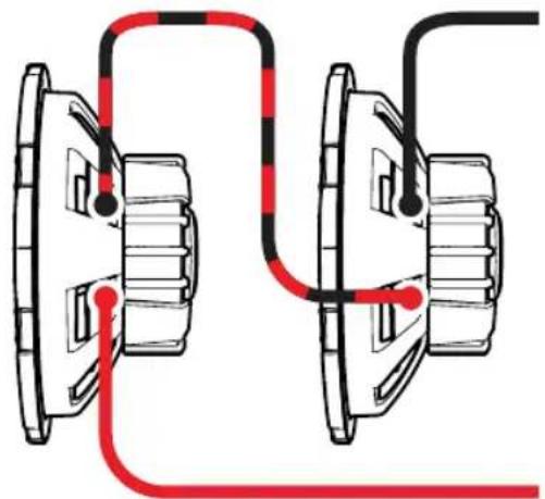
WIRING
Series Wiring
Two 2Ω Woofers = 4Ω Load
Two 4Ω Woolers = 8Ω Load
Parallel Wiring
Figure 1
Two 2Ω Woofers = 1Ω Load
Two 4Ω Woofers = 2Ω Load
natural_image
Pure mechanical diagram showing two gear assemblies connected by red and black lines (no text or symbols)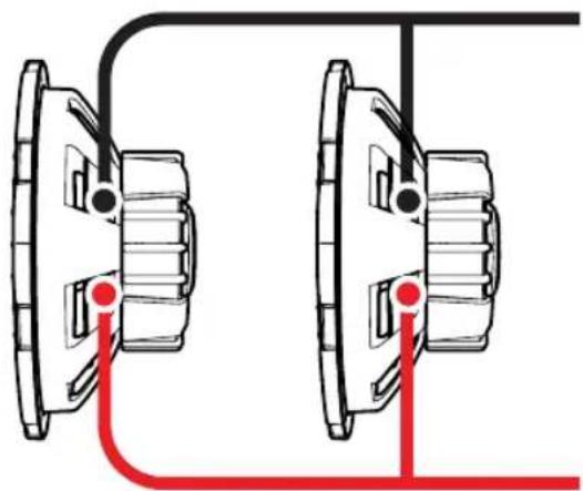
natural_image
Diagram of two mechanical components connected by a cable, with red lines indicating connection points (no text or symbols present)2
SEALED ENCLOSURE APPLICATIONS
CompVT woofers perform well in any size sealed enclosure between the minimum and maximum volume recommendations. These systems will exhibit benefits of both designs: Minimum produces high-impact bass, and maximum generates low bass frequency protraction. Overall, the system will sound more like the recommended enclosure design it is closest to in enclosure volume. These enclosure recommendations have been calculated with the airspace inside the enclosure and include the displacement of the woofer. All sealed-enclosure airspace should be filled to 50% loose poly-fi I (polyester fiberfill) stuffing. Do not make the airspace greater than the maximum enclosure volume recommendation.
Sealed Minimum
| Model | Volume ft ^2 [L] | Power | Handling |
| CVT10 | .8 [22.7] | 350W RMS | |
| CVT12 | 1 [28.3] | 350W RMS | |
Sealed Maximum
| Model | Volume ft ^5 [L] | Power | Handling |
| CVT10 | 3 [85] | 300W RMS | |
| CVT12 | 4.6 [130] | 300W RMS | |
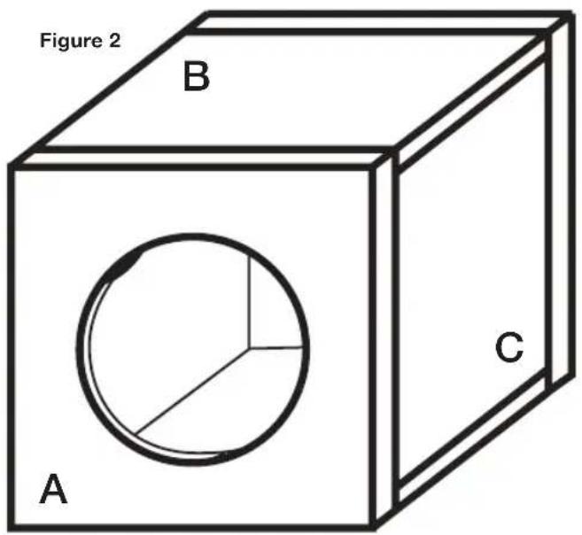
Panel Dimensions for Sealed Minimum enclosures using 3/4" (1.9cm) thick MDF (See Figure 2)
| Model | Volume | ft[L] | Panel A in. [cm] | Panel B in. [cm] | Panel C in. [cm] |
| CVT10 | .8 [22.7] | 18x30.5 [45.7x77.5] | 3x30.5 [7.6x77.5] | 3x16.5 [7.6x41.9] | |
| CVT12 | 1 [28.32] | 18x36 [45.7x91.4] | 3.125x36 [7.9x91.4] | 3.125x16.5 [7.9x41.9] |
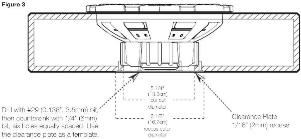
To make the most efficient use of space when building the Sealed Minimum enclosure for your CompVT subwoofer, you must use the included clearance plate. The clearance plate allows the CompVT subwoofer to sit recessed within the back panel of the subwoofer box to minimize the enclosure's depth. The clearance plate must seal tightly. First, use a plunging router, straight-cut bit, and a circle jig to create a 1/16" (2mm) deep recess with an outer diameter of 6 1/2" (16.7cm) and an inner diameter of approximately 5" (12.7cm). Center the recess behind the subwoofer on the back panel. Then, cut a 5 1/4" (13.3cm) diameter hole in the center of the recess all the way through the back panel. Using the clearance plate as a reference, drill the six screw holes with a #29 (0.136", 3.5mm) drill bit. Next, countersink each screw hole using a 1/4" (6mm) drill or countersinking bit so the clearance plate will fit tightly against the back panel. Remove the paper backing from the foam gasket and adhere it to the inside of the clearance plate. Then, fasten the clearance plate to the box with six #8 screws. See Figure 3.
VENTED ENCLOSURE APPLICATIONS
The smaller enclosures are best for use in limited-space applications. The larger recommended enclosures will yield slightly more bass at the lowest frequencies.
| Vented Minimum | CompVT10 | CompVT12 |
| Box Volume, ft3[L] 1.25 [35.4] 1.75 [49.6] | ||
| Port Opening, in x in [cm x cm] 2x10.5 [5.1x26.7] 2.5x12.5 [6.4x31.8] | ||
| Port Length, in [cm] 20 [50.8] 20 [50.8] | ||
| Power Handling, RMS 200 300 | ||
| Vented Maximum | CompVT10 | CompVT12 |
| Box Volume, ft3[L] 1.75 [49.6] 2.25 [63.7] | ||
| Port Opening, in x in [cm x cm] 2.5x10.5 [6.4x26.7] 3x12.5 [7.6x31.8] | ||
| Port Length, in [cm] 20 [50.8] 20.5 [52.1] | ||
| Power Handling, RMS 200 300 |
The vented minimum design increases bass efficiency and fits in many space-limited applications. Although it is the smallest recommended vented enclosure, the output from 30Hz–80Hz will be considerably higher than that of a sealed box. The maximum vented design has even more output in this frequency band. The maximum vented enclosure is the largest and most efficient design.
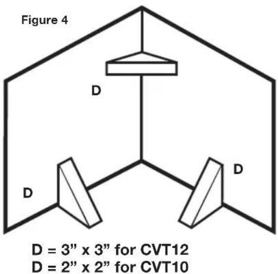
BOX BUILDING NOTES
Use 3/4" (1.9cm) or thicker MDF (medium density fi berboard) and seal the joints with silicone. Use the "template" inside your CompVT's shipping carton to mark the mounting hole, then cut directly on the line. These designs need internal bracing. Add triangular bracing between each of the larger unsupported panels. See
Figure 4.
4
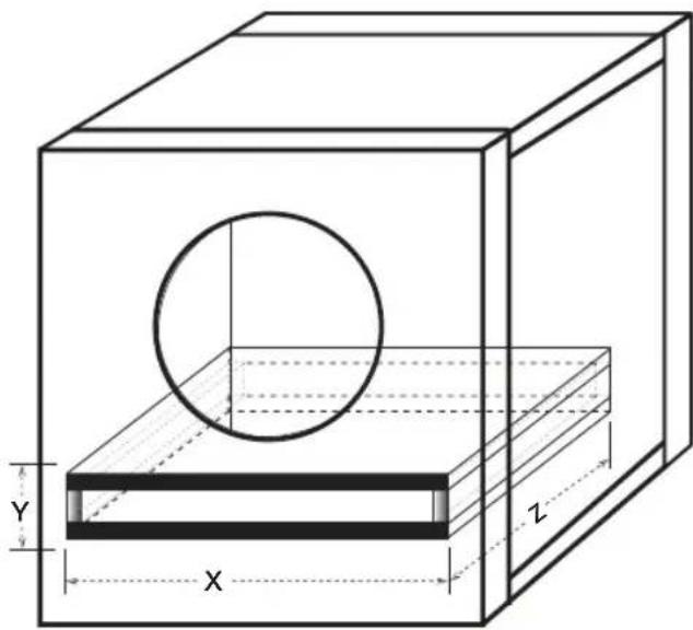
All the cubic feet (L) measurements in this manual include the displacement of the woofer. For the vented enclosures the displacement of the port must be calculated and added to the internal volume of the final design.
Use the outer dimensions of the port and multiply "X X Y X Z", then convert to cubic feet. For example, the CVT12 Vented Minimum design's external port dimensions are, using 3/4" (1.9cm) MDF:
(12.5" + 1.5" total MDF wall thickness) x
(2.5" + 1.5" total MDF wall thickness) x
(20") x (1 ft³ / 1728 in³) = .65 ft³,
Then, add this number to the internal volume of the enclosure. 1.75 ft^3 + .65 ft^3 = 2.4 ft^3 . See
Figure 5.
Due to the necessary length of these ports, you may want to fold the port along the bottom and back walls. It will be impractical to use round ports for these designs.
Do not install a port opening against a solid surface, such as an internal brace, back-panel or trunk wall, seat or interior panel of your vehicle. The port opening must remain unobstructed. Use the smallest dimension of the rectangular port as the minimum amount of space between the port opening and any solid surface to insure unrestricted airflow.
Figure 5
natural_image
3D diagram of a rectangular box with internal circular cutout and labeled dimensions X, Y, Z (no text or symbols beyond labels)If you prefer an ultra-smooth bass response, you should loosely fi ll your CompVT enclosure with poly-fi I stuffi ng. Vented designs will require covering the end of the port (located inside the box) with grill cloth, chicken wire, or expanded metal to prevent the poly-fi I from exiting the port. The use of poly-fi I will slightly decrease eff ciency, but will deepen and extend the low frequency output.
For more advice on box building, refer to your Authorized KICKER Dealer, or click on the Support tab on the KICKER homepage, www.kicker.com. Please e-mail support@kicker.com or call Technical Support at (405) 624-8583 for specific or unanswered questions.
Sound Check: Poor bass response? Check the system phasing by reversing the positive and negative speaker connections on the subwoofer. If the bass improves, then the subwoofer was out of phase in reference to the rest of the audio system.
Note: All specifications and performance figures are subject to change. Please visit www.kicker.com for the most current information. To get the best performance from your new KICKER Subwoofer, we recommend using genuine KICKER Accessories and Wiring. Please allow two weeks of break-in time for the subwoofer to reach optimum performance.
If mounting in trunk space or other compartments of the vehicle, pay attention to cable lines, trunk springs, hinges and seat mechanisms that could cause problems with the operation of the vehicle or stereo system. Carefully lay the stereo system cables; pay attention to seat fasteners and other items that could harm the cables.
WARNING: KICKER products are capable of producing sound levels that can permanently damage your hearing! Turning up a system to a level that has audible distortion is more damaging to your ears than listening to an undistorted system at the same volume level. The threshold of pain is always an indicator that the sound level is too loud and may permanently damage your hearing. Please use common sense when controlling volume.
KKICKER®
natural_image
Diagram of two mechanical gears connected by red and black wiring (no text or symbols)natural_image
Diagram of two mechanical components connected by a wire, showing shafts and housing (no text or symbols)6

natural_image
Pure mechanical diagram showing two gear assemblies connected by red and black lines (no text or symbols)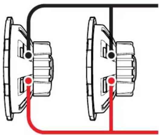
natural_image
Diagram of two mechanical gears connected by wires, with red lines indicating connection points (no text or symbols)BASSBOXEN MIT GESCHLOSSENEM GEHÄUSE
natural_image
Diagram of two mechanical components connected by red and black lines, no text or symbols present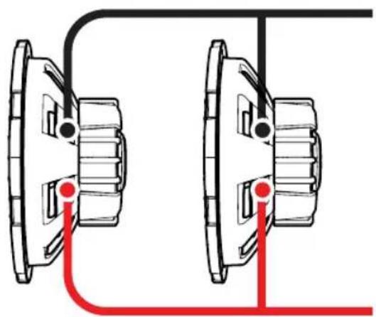
natural_image
Diagram of two mechanical gears connected by a string, with red lines indicating connection points (no text or symbols)ENCEINTES CLOSES
natural_image
Technical diagram of a rectangular box with internal circular cutout and labeled dimensions X, Y, Z (no text or symbols beyond labels)When purchased from an Authorized KICKER Dealer, KICKER warrants this product to be free from defects in material and workmanship under normal use for a period of ONE (1) YEAR from date of original purchase. If this product is identified as "Refurbished" or "B Goods", the warranty is limited to a period of THREE (3) MONTHS from date of original purchase. In all cases you must have the original receipt. Should service be necessary under this warranty for any reason due to manufacturing defect or malfunction during the warranty period, KICKER will repair or replace (at its discretion) the defective merchandise with equivalent merchandise. Warranty replacements may have cosmetic scratches and blemishes. Discontinued products may be replaced with more current equivalent products. This warranty is valid only for the original purchaser and is not extended to owners of the product subsequent to the original purchaser. Any applicable implied warranties are limited in duration to a period of the express warranty as provided herein beginning with the date of the original purchase at retail, and no warranties, whether express or implied, shall apply to this product thereafter. Some states do not allow limitations on implied warranties; therefore, these exclusions may not apply to you. This warranty gives you specific legal rights; however you may have other rights that vary from state to state.
WHAT TO DO IF YOU NEED WARRANTY OR SERVICE:
Defective merchandise should be returned to your local Authorized Stillwater Designs (KICKER) Dealer for warranty service. Assistance in locating an Authorized Dealer can be found at www.kicker.com or by contacting Stillwater Designs directly. You can confirm that a dealer is authorized by asking to see a current authorized dealer window decal.
If it becomes necessary for you to return defective merchandise directly to Stillwater Designs (KICKER), call the KICKER Customer Service Department at (405) 624-8510 for a Return Merchandise Authorization (RMA) number. Package only the defective items in a package that will prevent shipping damage, and return to:
Stillwater Designs, 3100 North Husband St, Stillwater, OK 74075
The RMA number must be clearly marked on the outside of the package. Please return only defective component systems. The return of functioning items increases your return freight charges. Non-defective items will be returned freightcollect to you. For example, if a subwoofer is defective, only return the defective subwoofer, not the entire enclosure. Include a copy of the original receipt with the purchase date clearly visible, and a "proof-of-purchase" statement listing the Customer's name, Dealer's name and invoice number, and product purchased. Warranty expiration on items without proof-of-purchase will be determined from the type of sale and manufacturing date code. Freight must be prepaid; items sent freight-collect, or COD, will be refused.
WHAT IS NOT COVERED?
This warranty is valid only if the product is used for the purpose for which it was designed. It does not cover:
o Damage due to improper installation
o Subsequent damage to other components
o Damage caused by exposure to moisture, excessive heat, chemical cleaners, and/or UV radiation
o Damage through negligence, misuse, accident or abuse. Repeated returns for the same damage may be considered abuse
o Any cost or expense related to the removal or reinstallation of product
o Speakers damaged due to amplifier clipping or distortion
o Items previously repaired or modified by any unauthorized repair facility
o Return shipping on non-defective items
o Products with tampered or missing barcode labels
o Products with tampered or missing serial numbers
o Products returned without a Return Merchandise Authorization (RMA) number
o Products purchased from an UNAUTHORIZED dealer
o Freight Damage
o The cost of shipping product to KICKER
o Service performed by anyone other than KICKER
HOW LONG WILL IT TAKE?
NOTE: All specifications and performance figures are subject to change. Please visit the www.kicker.com for the most current information.
KICKER strives to maintain a goal of one-week service for all acoustics (subwoofers, midrange drivers, tweeters, crossovers, etc) returns. Delays may be incurred if lack of replacement inventory or parts is encountered. Failure to follow these steps may void your warranty. Any questions can be directed to the KICKER Customer Service Department at (405) 624-8510. Contact your International KICKER dealer or distributor concerning specific procedures for your country's warranty policies.
INTERNATIONAL WARRANTY
Contact your International KICKER dealer or distributor concerning specific procedures for your country's warranty policies.
Our goods come with guarantees that cannot be excluded under the Australian Consumer Law. You are entitled to a replacement or refund for a major failure and for compensation for any other reasonably foreseeable loss or damage. You are also entitled to have the goods repaired or replaced if the goods fail to be of acceptable quality and the failure does not amount to a major failure.
©2015 Stillwater Designs
- WIRING
- SEALED ENCLOSURE APPLICATIONS
- VENTED ENCLOSURE APPLICATIONS
- BOX BUILDING NOTES
- Figure 4.
- Figure 5.
- KKICKER®
- BASSBOXEN MIT GESCHLOSSENEM GEHÄUSE
- ENCEINTES CLOSES
- WHAT TO DO IF YOU NEED WARRANTY OR SERVICE:
- Stillwater Designs, 3100 North Husband St, Stillwater, OK 74075
- WHAT IS NOT COVERED?
- HOW LONG WILL IT TAKE?
- INTERNATIONAL WARRANTY
Brand : KICKER
Model : CompVT 43CVT122
Category : Subwoofer