
JEHSCU0750CL3 - Fridge DAIKIN - Free user manual and instructions
Find the device manual for free JEHSCU0750CL3 DAIKIN in PDF.

| Product Type | Scroll refrigeration unit for low temperature application |
| Brand | Daikin |
| Model | JEHSCU0750CL3 |
| Series | 4 |
| Compressor | ZF25K5E-TFD (scroll) |
| Compatible refrigerants | R404A, R407A, R407F, R448A, R449A |
| COP (R404A) | 1.82 |
| Compressor displacement | 21.4 m³/h |
| Oil charge | 1.9 L (polyester oil) |
| Electrical supply | 400 V / 3 phases / 50 Hz |
| Power input (R404A) | 9.15 kW |
| Nominal current (R404A) | 8.75 A |
| Maximum fuse current (MFA) | 16 A |
| Condenser air flow | 5750 m³/h |
| Liquid receiver volume | 13.6 L |
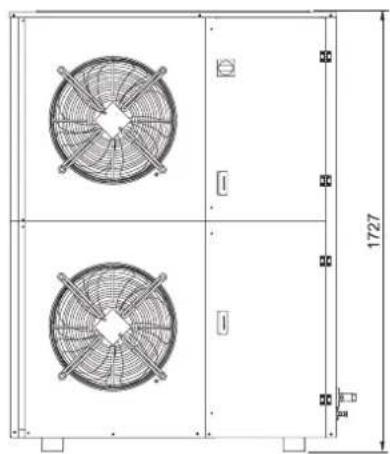
| Dimensions (L × W × H) | 1348 × 605 × 1727 mm |
| Net weight | 203 kg |
| Sound pressure level | 41 dB(A) at 10 m |
| Suction connection | 1-1/8" |
| Liquid connection | 1/2" |
| Temperature range | Low temperature (evaporation -35°C typical) |
| Installation | Outdoor, adequate ventilation, service space |
| Maintenance | Condenser coil cleaning every 3 months, check oil level |
Frequently Asked Questions - JEHSCU0750CL3 DAIKIN
User questions about JEHSCU0750CL3 DAIKIN
0 question about this device. Answer the ones you know or ask your own.
Ask a new question about this device
Download the instructions for your Fridge in PDF format for free! Find your manual JEHSCU0750CL3 - DAIKIN and take your electronic device back in hand. On this page are published all the documents necessary for the use of your device. JEHSCU0750CL3 by DAIKIN.
USER MANUAL JEHSCU0750CL3 DAIKIN
Installation Manual
Operation Manual
(Original Instruction)
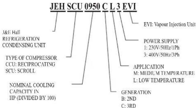
Reciprocating condensing unit for medium temperature application
| Series 1 |
| JEHCCU0040CM1 |
| JEHCCU0050CM1 |
| JEHCCU0051CM1 |
| JEHCCU0063CM1 |
| JEHCCU0067CM1 |
| JEHCCU0077CM1 |
| JEHCCU0095CM1 |
| JEHCCU0100CM1 |
| JEHCCU0113CM1 |
| Series 2 |
| JEHCCU0140CM1 |
| JEHCCU0140CM3 |
| JEHCCU0150CM1 |
| JEHCCU0150CM3 |
| JEHCCU0225CM1 |
| JEHCCU0225CM3 |
| JEHCCU0300CM1 |
| JEHCCU0300CM3 |
Reciprocating condensing unit for low temperature application
Series 1 JEHCCU0115CL1
Scroll condensing unit for medium temperature application
| Series 2 |
| JEHSCU0200CM1 |
| JEHSCU0200CM3 |
| JEHSCU0250CM1 |
| JEHSCU0250CM3 |
| JEHSCU0300CM1 |
| JEHSCU0300CM3 |
| JEHSCU0350CM3 |
| Series 3 |
| JEHSCU0400CM3 |
| JEHSCU0500CM3 |
| JEHSCU0600CM3 |
| JEHSCU0680CM3 |
| Series 4 |
| JEHSCU0800CM3 |
| JEHSCU1000CM3 |
Scroll condensing unit for low temperature application
Series 2 JEHSCU0200CL3 JEHSCU0300CL3
Series 3 JEHSCU0400CL3 JEHSCU0500CL3 JEHSCU0600CL3
Series 4 JEHSCU0750CL3 JEHSCU0950CL3 EVI
Contents
- Nomenclature 2
- Safety and Health 2
- Installation & commissioning 2
- Decommissioning & Disposal 9
- Checklist 9
- Service and Maintenance 9
- F gas Regulations 10
- Trouble Shooting 10
- Specifications 11
- Outline Drawings 13
- Electrical Data 16
- Appendix 23
1. Nomenclature
2. Safety and Health
General Information
Important Note
Only a qualified refrigeration engineer who is familiar with refrigeration systems and components, including all controls should perform the installation and start-up of the system. To avoid potential injury, use care when working around coil surfaces or sharp edges of metal cabinets. All piping and electrical wiring should be installed in accordance with all applicable codes, ordinances and local by-laws.
This appliances is not intended for use by persons (including children) with reduced physical, sensory or mental capabilities, or lack of experience and knowledge, unless they have been given supervision or instruction concerning use of the appliance by a person responsible for their safety. Children should be supervised to ensure that they do not play with the appliance.
- Ensure the unit received is the correct model for the intended application.
- Ensure refrigerant, voltage, are suitable for the proposed application and environment.
-
Installation and maintenance are to be performed only by qualified personnel who are familiar with local codes and regulations, and experienced with this type of equipment.
• The condensing unit is delivered with a nitrogen holding charge. -
The condensing unit contains moving machinery and electrical power hazards. May cause severe injury or death. Disconnect and shut off power before installation or service of the equipment.
- Refrigerant release into the atmosphere is illegal. Proper evacuation, handling and leak testing procedures must be observed at all times.
- Condensing unit must be earthed Improper earthing may result in electric or fire.
- Be sure to switch off the unit before touching any electrical parts. Touching a live part may result in electric shocks or fire.
- The electrical covers and condenser fan guard must remain fitted at all times.
- Use of the condensing unit outside of design conditions and application for which units were intended may be unsafe and be detrimental to the unit, regardless short or long term operation.
- The condensing units are not designed to withstand loads or stresses from other equipment or personnel. Such extraneous loads or stress may cause failure / leak / injury. In some circumstances, a suction accumulator (not supplied) component may be required, it offers protection against refrigerant flood back during operation. It helps protect against off-cycle migration by adding internal free volume to the low side of the system.
- Test must be conducted to ensure the amount of off-cycle migration to the compressor does not exceed the compressor's charge limit.
- Wherever possible the system should be installed to utilize a pump down configuration. For unit Series 1 JEHCCU040CM1 and JEHCCU0050CM1, it is advisable to connect with thermostat cut off configuration using the reserved terminal in control box.
- After installation, the system should be allowed to run for 3 – 4 hours. The oil level should be checked after 3 – 4 hours run time and topped up as necessary. The oil level should not be lower than quarter of the compressor oil sight glass.
3. Installation & Commissioning
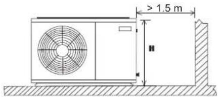
3.1 Unit site location
- In order to achieve maximum cooling capacity, the installation location for condensing unit should be carefully selected.
- Install the condensing unit in such a way so that hot air distributed by the condensing unit cannot be drawn in again (as in the case of short circuit of hot discharge air). Allow sufficient space for maintenance around the unit.
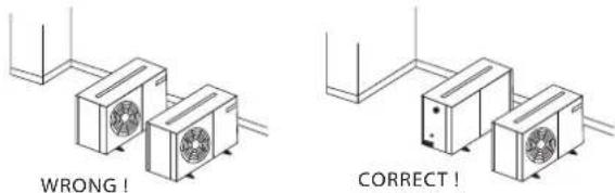
- Ensure that there is no obstruction of air flow into or out of the unit. Remove obstacles which block air intake or discharge.
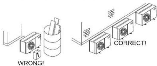
- The location must be well ventilated, so the unit can draw in and distribute plenty of air thus lowering the condensing temperature.
- To optimize the unit running conditions, the condenser coil must be cleaned at regular intervals.
3.2 Installation Clearance
- The installation location should allow sufficient space for air flow and maintenance around the unit.
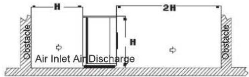
- To allow sufficient space for doing service or installation.
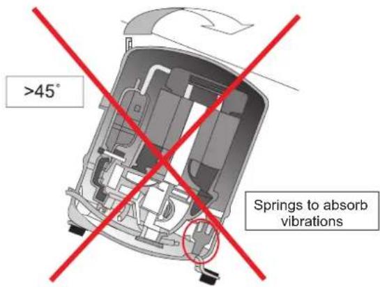
3.3 Compressor handling
To ensure compressor reliability, the condensing unit and the compressor must not be tilt greater than an angle of 45^ . Otherwise, the compressor can fall from its 3 compressor housing spring, which results in noisyvibrations during operation and possible to breakdown.
3.4 Field Piping
To
ensure
Important Note Line sizing should only be determined by qualified personnel. All local codes of practice must be observed in the installation of refrigerant piping.
satisfactory operation and performance, the following points should be noted for field piping arrangements,
- Couples one indoor unit with one outdoor condensing unit only.
- Release all the pre-charged nitrogenbefore pipework connection.
- Connecting pipe size for suction and liquid line must same as attaches to the condensing unit. Correct line sizing will minimize the pressure drop and maintain sufficient gas velocity for proper oil return.
- Pipework routes must be as simple and as short as possible. Avoid low points on pipework where oil can accumulate.
- Use only clean, dehydrated refrigeration grade copper tube with large radius elbows. The piping shall be kept with enough bending radius.
- Braze without over filling to ensure there is no excess solder into the tube.
- To prevent oxidation, blow nitrogen through pipework when brazing.
• Install insulation on all suction lines after pressure test. - Adequately support all pipe work at a maximum of 2 meter intervals.
- For the condition where the outdoor condensing unit is above the indoor unit, the height difference between units shall be less than 25 m and install oil trap on suction pipe every 4 m height. The suction pipe must always be fitted with U-trap at the bottom.
- For the condition where the outdoor condensing unit is below the indoor unit, the height difference between units shall be less than 4 m. Pipe trap shall be installed upward on outlet of indoor unit (suction pipe).
• The recommended piping length is 25 m or less. - Additional oil might be required in case field piping is long or with many oil traps. Check the oil level of the compressor to decide to add the oil after minimum 2 hours operation.
- It is recommended as well to install the MOP (Maximum Operation Pressure), expansion valve for medium evaporating temperature units, if the working suction pressure during start procedure especially after defrost cycle, is out of the limit, as refer to the table provided.
Recommend compressor working pressure range:
Medium Temperature
| Compressor Model | AE/AJ ZBMTZ | ||||||
| Refrigerant | R404A | R134a | R404A | R134a | R407C | R404A | R134a |
| Working Pressure Range High Side, (barg) | 13.2-27.7 | 6.7-15.8 | 13.2-27.7 | 7.9-15.8 | 12.5-29.4 | 7.14-27.6 | 6.6-15.8 |
| Working Pressure Range Low Side, (barg) | 1.5-8.3 | 0.1-3.9 | 1.0-7.2 | 0.6-4.7 | 1.4-6.6 | 1.98-7.14 | 0.6-3.8 |
Low Temperature
| Compressor Model | AJ | NTZ | ZF |
| Refrigerant | R404A | R404A | R404A |
| Working Pressure Range High Side, (barg) | 13.2-27.7 | 13.2-27.7 | 13.2-27.7 |
| Working Pressure Range Low Side, (barg) | 0.1-3.3 | 0.1-3.3 | 0.1-3.3 |
3.5 Pressure testing
- Make sure unit are isolated when pressure test on field piping, always use an inert, dry gas such as Nitrogen. Check for leak if there is reduction in holding pressure.
- The pressure differential between the high and low side of system shall not exceed below value.
| Compressor | Pressure differential |
| AE/AJ | 19 barg(275 psig) |
| MTZ/ZB/ZF | 30 barg(435 psig) |
- Test pressures used in factory as shown follows.
| Test pressure | |
| High side | Low side |
| 28 barg(405 psig) | 19 barg(275 psig) |
3.6 Leak detection
• Make sure that all isolation valves are open.
- Perform a leak test of the system using nitrogen mixed with the approved refrigerant for the unit.
- Do not use CFC for leak testing the condensing unit which intended for used with HFC refrigerants.
- The use of leak testing fluids is not recommended as this may interact with the lubricants own additives.
3.7 Vacuum - moisture removal
Important Note
Moisture prevents proper functioning of the compressor and the refrigeration system.
Air and moisture reduce service life and increase condensing pressure causing abnormally high discharge temperatures likely to destroy the oil's lubricating properties. The risk of acid formation is also increased by air and moisture and copper plating can be generated in this way. All these phenomena can cause mechanical and electrical failure.
Important Note
Ensure that a good quality vacuum pump is used to pull a minimum vacuum of -0.1 barg (250 microns) or less. Ensure that no pressure increase during 1 hour or more after stop vacuuming. If pressure increase, there is moisture or leakage along the pipeline.
3.8 Safety pressure switch settings
The pressure switch fitted to condensing units with auto reset for low pressure and manual reset for high pressure are NOT factory preset.
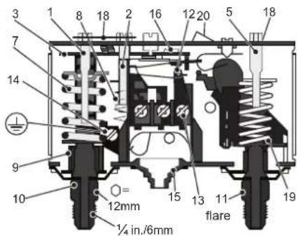
- Low pressure (LP) setting spindle
- Differential setting spindle, LP
- Main arm
- High pressure (HP) setting spindle
- Main spring
- Differential spring
- Bellows
- LP connection
-
HP connection
-
Switch
- Terminals
- Earth terminal
- Cable entry
- Tumbler
- Locking plate
- Arm
- Manual reset button
High pressure safety (Manual reset)
The high pressure safety switch is required to protect the compressor from working out of its envelope. The high pressure switch shall set equal or lower than below values depending on the type of refrigerant, application and the ambient condition.
| Model | AE/CAJ/TAJ MTZ/ZB/ZF | |||
| Refrigerant | R404A | R134a | R404A | R134a |
| Cut Out (barg) | 27.7 | 18 | 27.7 | 18 |
| Cut Out (psig) | 402 | 261 | 402 | 261 |
Low pressure safety (Auto reset)
The low pressure safety switch is used to avoid compressor operate at too low suction pressure or a vacuum condition. The low pressure safety cut out should never be set lower than value shown in following table. If pump down is used, the electrical circuitry should be arranged so that compressor restart is triggered by demand from thermostat rather than a reset low pressure switch.
* M: Medium temperature; L: Low temperature
| Model | AE/CAJ/TAJ MTZ | ZB/ZF | |||||||
| Refrigerant | R134a | R404AR | 404A R | 34a R40 | 7C R404A R134a | ||||
| Application | M* | L* | M* | M* | M* | M* | M* | L* | M* |
| Cut out (barg) | 1.5 | 0.1 | 0.5 | 1.0 | 0.6 | 1.4 | 2.0 | 0.1 | 0.6 |
| Cut out (psig) | 21.8 | 1.5 | 7.3 | 14.5 | 8.7 | 20.3 | 29.0 | 1.5 | 8.7 |
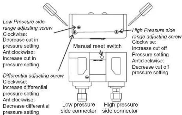
The low pressure cut off pressure is the setting of cut in minus the differential.
Important Note
There must be no more than 10 compressor starts per hour. A higher number reduces the service life of the compressor. If necessary, use an anti-short-cycle timer in the control circuit. Minimum a 2 minutes runtime after each start of compressor and a 3 minute idle time after each stop & start are recommended. Only during the pump down cycle may the compressor run for much shorter intervals.
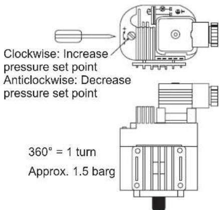
3.9 Fan speed controller setting
The fan speed controller control the condensing head pressure via speed regulating according to the ambient temperature. The setting for fan cut off should be set higher than the recommended value in table below, to maintain enough liquid sub cooling ahead of TXV for low ambient application.
The fan speed controller is factory set to 19 bar for operation with R4*** series refrigerant to ensure compressor always operates within envelope at all declared working condition.
Higher energy efficiency as shown in eco design sheet can be obtained with the setting shown in below table:
For model in Series 1:
| Refrigerant | R404A | R134a |
| Setting (bar) Cut in | 16* | 10 |
| Setting (bar) Differential | 7* | 7 |
*Factory default setting
For model in Series 2, 3 and 4:
| Application | Medium Temp Low Temp | ||
| Refrigerant | R404A/R407F/R407A/R448A/R449A | R134a | R404A/R407F/R407A/R448A/R449A |
| Setting (barg) | 19*(Series 2) | 13(Series 2 &3) | 13(except EVI unit) |
| 10(Series 3 & 4) | 10(Series 4) | 17(JEHSCU0950CL3 EVI) | |
*Factory default setting
Cut off: Fan motor stops when the pressure decreases below the value Pmin.
Note:
F.V.S. = Full Voltage Set Point (pressure setting for maximum speed)
E.P.B. = Effective Proportional Band (6 bar)
Pmin = (F.V.S. - 6)
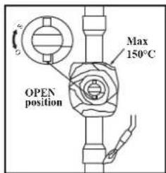
3.10 Commissioning of the Condensing Unit
Please make sure that all manual service valves are fully opened before starting the system for the first time. This includes external and internal shut off valves as well as liquid receiver valve in the unit. The ball valve open position is shown as below:
3.11 Compressor electrical wiring
Verification of proper rotation direction is made by observing that suction pressure drops and discharge pressure rises when the compressor is energized. Reverse rotation of a scroll compressor also results in substantially reduced current draw. Suction temperature will be high, discharge temperature will be low and the compressor may generate abnormal noise.
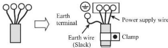
3.12 Earthing of Condensing Unit
Installation of earth wire must be made to grounding screw (labelled with earth label) before connecting the live wires. The earth wire shall be slack as shown in below diagram.
3.13 Tightening torque - rotolock connection
| Unit Model | Series | Compressor Model | Rotolock (Suction) Thread: Tightening Torque (N.m) | Rotolock (Discharge) Thread: Tightening Torque (N.m) | |
| Medium TemperatureLow Temperature | JEHCCU0050CM1 | 1 | AE4460Z-FZ1C | NOT APPLICABLE(BRAZED - CONNECTION) | |
| JEHCCU0067CM1 | CAJ9480Z | ||||
| JEHCCU0100CM1 | CAJ9510Z | ||||
| JEHCCU0113CM1 | CAJ9513Z | ||||
| JEHCCU0040CM1 | AE4440Y-FZ1A | ||||
| JEHCCU0051CM1 | CAJ4461Y | ||||
| JEHCCU0063CM1 | CAJ4476Y | ||||
| JEHCCU0077CM1 | CAJ4492Y | ||||
| JEHCCU0095CM1 | CAJ4511Y | ||||
| JEHCCU0140CM1 | 2 | CAJ4517Z | |||
| JEHCCU0140CM3 | TAJ4517Z | ||||
| JEHCCU0150CM1 | MTZ18-5VM | NOT APPLICABLE(BRAZED - CONNECTION) | 1"-14 UNS(70-80N.m) | ||
| JEHCCU0150CM3 | MTZ18-4VM | ||||
| JEHCCU0225CM1 | MTZ28-5VM | ||||
| JEHCCU0225CM3 | MTZ28-4VM | ||||
| JEHCCU0300CM1 | MTZ36-5VM | ||||
| JEHCCU0300CM3 | MTZ36-4VM | ||||
| JEHSCU0200CM1 | ZB15KQE-PFJ | NOT APPLICABLE(BRAZED - CONNECTION) | |||
| JEHSCU0200CM3 | ZB15KQE-TFD | ||||
| JEHSCU0250CM1 | ZB19KQE-PFJ | ||||
| JEHSCU0250CM3 | ZB19KQE-TFD | ||||
| JEHSCU0300CM1 | ZB21KQE-PFJ | ||||
| JEHSCU0300CM3 | ZB21KQE-TFD | ||||
| JEHSCU0350CM3 | ZB26KQE-TFD | ||||
| JEHSCU0400CM3 | 3 | ZB29KQE-TFD | |||
| JEHSCU0500CM3 | ZB38KQE-TFD | ||||
| JEHSCU0600CM3 | ZB45KQE-TFD | ||||
| JEHSCU0680CM3 | ZB48KQE-TFD | ||||
| JEHSCU0800CM3 | 4 | ZB58KCE-TFD | 1-3/4"-12UNF(135-160 N.m) | 1-1/4"-12UNF(110-135 N.m) | |
| JEHSCU1000CM3 | ZB76KCE-TFD | ||||
| JEHCCU0115CL1 | 1 | CAJ2446Z | NOT APPLICABLE(BRAZED - CONNECTION) | ||
| JEHSCU0200CL3 | 2 | ZF06K4E-TFD | 1-1/4"-12UNF(110-135 N.m) | 1"-14 UNS(70-80N.m) | |
| JEHSCU0300CL3 | ZF09K4E-TFD | ||||
| JEHSCU0400CL3 | 3 | ZF13K4E-TFD | |||
| JEHSCU0500CL3 | ZF15K4E-TFD | ||||
| JEHSCU0600CL3 | ZF18K4E-TFD | ||||
| JEHSCU0750CL3 | 4 | ZF25K5E-TFD | 1-1/4"-12UNF(110-135 N.m) | ||
| JEHSCU0950CL3 EVI | ZF18KVE-TFD-EVI | 1"-14 UNS(70-80N.m) | |||
3.14 Series 4 EVI Unit
3.14.1 Piping Size Selection
Sizing of liquid and suction lines for EVI model will be different from standard scroll models. Piping sizes of this model need to follow the recommended correction coefficient of cooling capacity. This is vital as if the pipework selected is oversized, especially for the suction pipe, the gas velocity will be decreased at low mass flow rate / low evaporating temperature, causing oil return problems. Undersized suction lines will also cause decreased capacity due to increased pressure drop.
The correction factor of refrigerant R404A is shown as below table:
| Ta\Te | (Watts) | -40 | -35 | -30 | -25 | -20 |
| 27 | CF | 0.64 | 0.66 | 0.68 | 0.70 | 0.72 |
| 32 | CF | 0.61 | 0.63 | 0.65 | 0.67 | 0.69 |
| 35 | CF | 0.59 | 0.61 | 0.63 | 0.65 | 0.67 |
| 38 | CF | 0.57 | 0.59 | 0.61 | 0.63 | 0.65 |
| 43 | CF | 0.54 | 0.55 | 0.57 | 0.58 | 0.60 |
For instance,
At condition of Te -35°C, Ta +32°C
Refrigerant R404A
Published cooling capacity = 5.9kW.
Cooling capacity = Correction factor x Published cooling capacity
$$ = 0. 6 3 \times 5. 9 \mathrm{kW} $$
$$ = 3. 7 0 7 \mathrm{kW} $$
Therefore, the pipe sizes should be selected against the corrected capacity of 3.71kW.
The correction factor of refrigerant R407A is shown as below table:
| Ta\Te | (Watts) | -40 | -35 | -30 | -25 | -20 |
| 27 | CF | 0.73 | 0.73 | 0.73 | 0.73 | 0.73 |
| 32 | CF | 0.68 | 0.69 | 0.69 | 0.70 | 0.70 |
| 35 | CF | 0.65 | 0.66 | 0.67 | 0.67 | 0.68 |
| 38 | CF | 0.62 | 0.63 | 0.64 | 0.65 | 0.66 |
| 43 | CF | 0.57 | 0.58 | 0.60 | 0.61 | 0.63 |
The correction factor of refrigerant R407F is shown as below table:
| Ta\Te | (Watts) | -40 | -35 | -30 | -25 | -20 |
| 27 | CF | 0.72 | 0.73 | 0.73 | 0.73 | 0.72 |
| 32 | CF | 0.68 | 0.68 | 0.69 | 0.69 | 0.69 |
| 35 | CF | 0.65 | 0.66 | 0.66 | 0.67 | 0.67 |
| 38 | CF | 0.62 | 0.63 | 0.64 | 0.65 | 0.65 |
| 43 | CF | 0.57 | 0.58 | 0.60 | 0.61 | 0.62 |
The correction factor of refrigerant R448A/R449A is shown as below table:
| Ta\Te | (Watts) | -40 | -35 | -30 | -25 | -20 |
| 27 | CF | 0.71 | 0.72 | 0.71 | 0.72 | 0.72 |
| 32 | CF | 0.67 | 0.68 | 0.68 | 0.68 | 0.69 |
| 35 | CF | 0.65 | 0.65 | 0.65 | 0.66 | 0.67 |
| 38 | CF | 0.62 | 0.63 | 0.63 | 0.64 | 0.65 |
| 43 | CF | 0.58 | 0.59 | 0.59 | 0.60 | 0.61 |
3.14.2 Insulation Selection
The liquid pipe connecting CCU service valve to the evaporator must be well insulated with recommended wall thickness of minimum 34 .
3.14.2 Expansion Valve Selection
The lower liquid temperature of the EVI unit can increase evaporator expansion valve capacities. Selection of the expansion valve needs to be done based on the expected amount of sub-cooling shown in below tables:
(A.) R404A
| Amount of Sub-cooling (K) | |||||
| Ta\Te | -40 | -35 | -30 | -25 | -20 |
| 27 | 39.9 | 36.9 | 33.9 | 30.9 | 27.9 |
| 32 | 40.9 | 37.9 | 34.9 | 31.9 | 28.9 |
| 35 | 41.5 | 38.5 | 35.5 | 32.5 | 29.5 |
| 38 | 42.1 | 39.1 | 36.1 | 33.1 | 30.1 |
| 43 | 43.1 | 40.1 | 37.1 | 34.1 | 31.1 |
(B.) R407A
| Amount of Sub-cooling (K) | |||||
| Ta\Te | -40 | -35 | -30 | -25 | -20 |
| 27 | 33.1 | 32.8 | 32.4 | 32.1 | 31.8 |
| 32 | 38.0 | 37.0 | 35.9 | 34.9 | 33.8 |
| 35 | 41.0 | 39.5 | 38.0 | 36.5 | 35.0 |
| 38 | 43.9 | 42.0 | 40.1 | 38.1 | 36.2 |
| 43 | 48.9 | 46.2 | 43.5 | 40.9 | 38.2 |
(C.) R407F
| Amount of Sub-cooling (K) | |||||
| Ta\Te | -40 | -35 | -30 | -25 | -20 |
| 27 | 33.8 | 33.5 | 33.1 | 32.8 | 32.5 |
| 32 | 38.8 | 37.8 | 36.7 | 35.7 | 34.6 |
| 35 | 41.9 | 40.4 | 38.8 | 37.3 | 35.8 |
| 38 | 44.9 | 42.9 | 41.0 | 38.9 | 37.0 |
| 43 | 50.0 | 47.2 | 44.5 | 41.8 | 39.0 |
(D.) R448A/R449A
| Amount of Sub-cooling (K) | |||||
| Ta\Te | -40 | -35 | -30 | -25 | -20 |
| 27 | 33.1 | 32.8 | 32.4 | 32.1 | 31.8 |
| 32 | 37.9 | 36.9 | 35.8 | 34.8 | 33.8 |
| 35 | 40.9 | 39.4 | 37.9 | 36.4 | 34.9 |
| 38 | 43.8 | 41.9 | 40.0 | 38.0 | 36.1 |
| 43 | 48.8 | 46.1 | 43.4 | 40.8 | 38.1 |
3.14.3 Controller EXD-HP1
The controller EXD-HP1 used in the Series 4 EVI unit operates as an economizer control. The setting of controller is preset by the factory and is password protected. Users are not allowed to change any settings in the controller.

Safety Instructions:
- Read installation instruction carefully. Failure to comply can result in device failure, system damage or personal injury.
- Only person having appropriate knowledge and skill are allowed to manipulate the controller.
- Disconnect all voltages from system before installation.
3.14.2 Electrical Installation
- Do not operate system before all cable connections are completed.
• Refer to wiring diagram for electrical connections. - Class II category transformer is required for 24VAC power supply
- Do not connect any EXD-HP1 input to main voltage as it will permanently damage the controller.
-
When connecting wires of expansion valve and pressure sensor, consider color coding as follow:
-
EXM : BR: BROWN; BL: BLUE, OR: ORANGE; YE: YELLOW; WH: WHITE
-
PT5 : BN: BROWN; WH: WHITE
3.14.3 Display / keypad unit (LEDs and button functions)
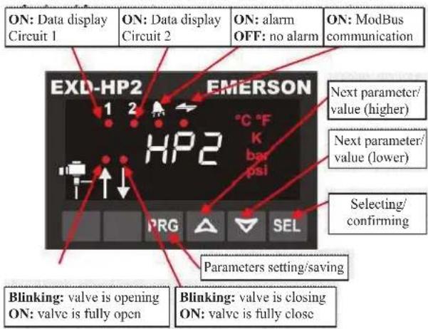
- In standard mode the superheat is shown at the display. In case of liquid injection and economizer function this changes to discharge temperature.
- To display other data of EXD-HP1 press "SEL" button for 1 second until index number according to below table appears. Release "SEL" button and the next variable data will appear. By repeating the procedure variable data can be displayed in sequence as measured superheat (K) → Measured suction pressure (bar) → valve position (%) → Measured suction gas temperature (°C) → Calculated saturated temperature (°C) → Measured discharge temperature (°C) (if economizer function is selected) → REPEATING
| Variable data | Controller EXD-HP1 |
| Default Superheat, K | 1 1 |
| Suction pressure, bar | 1 0 |
| Valve position, % | 1 0 |
| Suction gas temperature, °C | 1 0 |
| Saturation temperature, °C | 1 0 |
| Discharge temperature, °C | 1 0 |
3.14.4 Digital Input Di1/Di2
- The digital input Di1 is the interface between controller EXD-HP1 and system controller if Modbus communication has not been used.
- The digital status is dependent to operation of system's compressor or demand.
| Operating Condition | Digital input status |
| Compressor starts | Closed (Start) |
| Compressor stops | Open (Stop) |
3.14.5 Manual mode operation
Warning: All alarms are disabled during manual control. We do not recommend unattended operation of system during manual control.
- Press PRG and ▼ together for 5 seconds to access to manual mode operation.
- List of parameters in scrolling sequence by pressing button
| Code | Parameter description and choices | Min | Max | Factory setting | Field setting |
| 1Ho | Manual mode operation; circuit 1 00 = disabled; 1 = Enabled | 1 | 0 | ||
| 1HP | Valve opening (%) | 0 | 100 | 0 | |
| 2Ho | Manual mode operation; circuit 20 = disabled; 1 = Enabled | 0 | 1 | 0 | |
| 2HP | Valve opening (%) | 0 | 100 | 0 |
Manual alarm reset clearing functional alarms (except hardware error)
- Press PRG and together for 5 seconds. When the clearing is done, "CL" message appears for 2 seconds.

3.14.6 EXD-HP1 Error/Alarm handling
| Alarm code | Description | Related parameter | Valve W | What to do? | Requires manual reset after resolving alarm |
| 1E0/2E0 | Pressure sensor 1/2 error | - | Fully close | Check wiring connection and measure the signal 4 to 20 mA No | |
| 1E1/2E0 | Temperature sensor 1/2 error | - | Fully close | Check wiring connection and measure the resistance of sensor | No |
| 1Ed | Discharge hot gas temperature sensor 3 error | - | Operating | Check wiring connection and measure the resistance of sensor | No |
| 1AII/2AII | EXM/EXL electrical connection error | - | - | Check wiring connection and measure the resistance of winding | No |
| 1Ad | Discharge hot gas temperature above limit | Operating | Check valve opening/ check liquid flow for flash gas free/check discharge hot gas temperature sensor | No | |
| AF | Freeze protection | 1P4/2P4: 1 | Fully close | Check the system for cause of low pressure such as insufficient load on evaporator | No |
| AF blinking | 1P4/2P4: 2 | Fully close | Yes | ||
| AL | Low superheat (<0.5K) | 1uL/2uL: 1 | Fully close | Check wiring connection and operation of valve | No |
| AL blinking | 1uL/2uL: 2 | Fully close | Yes | ||
| AH | High superheat | 1uII/2uII: 1 | Operating | Check the system | No |
| AP | Low pressure | 1P9/2P9: 1 | Operating | Check the system for cause of low pressure such as refrigerant loss | No |
| AP blinking | 1P9/2P9: 2 | Operating | Yes |
Note: When multiple alarms occur, the highest priority alarm is displayed until being cleared.
Then the next highest alarm is displayed until all alarms are cleared.
Only then will parameters will be shown again
O-CU06-AUG17-3
All specifications are subjected to change by the manufacturer without prior notice. The English text is the original instruction. Other languages are the translations of the original instructions.
ENGLISH
4 Decommissioning & Disposal
At the end of the unit's useful life, a suitably qualified engineer should decommission it. The refrigerant and compressor oil are classed as hazardous waste and as such must be reclaimed and disposed of in the correct manner, including completion of waste transfer paperwork. The unit components must be disposed of or recycled as appropriate in the correct manner.
5. Checklist
- Ensure the high low pressure controls are configured properly.
- Ensure crankcase heater is energized minimum 12 hours prior to start up and permanently energized.
- Check the refrigerant is correct for intended use.
- Check all electrical connections.
- Check all electrical termination and circuits are correct.
- Check compressor oil level via compressor sight glass, the oil level should not be lower than quarter of sight glass.
- Check the TXV capacity sizing based on indoor unit capacity. Check TXV applicable refrigerant. Check position and condition of the sensing bulb fixing
- Observed the system pressures during the charging and initial operation process.
- Ensure that suction pressure will decrease, discharge pressure will increase. No abnormal noise from the compressor.
- Continue to charge the system until sight glass is clear. Make sure that high pressure is > 14 barg for R404A and > 8 barg for R134a when doing this charge adjustment operation. Continuous flow of clear refrigerant through the sight glass, with perhaps an occasional bubble at very high temperature indicates the refrigerant is at optimum.
- Check the compressor's discharge and suction pressure, to ensure it is within operating range. Discharge temperature should be within 50 to 90 °C and pressure should be around 15 to 26 barg (for system charged with R404A) and 8 to 16 barg (for system charged with R134a).
- Check the current of condensing unit and ensure it is below the motor circuit breaker setting value.
- Check condenser fan, ensure warm air blowing off the condenser coil.
- Check evaporator blower, ensure it's discharging cool air.
- Check suction superheat and adjust expansion valve to prevent liquid flood back to the compressor. Recommended 5 to 20 K of suction superheat.
- Do not leave the system unattended until the system has reached its normal operating condition and the oil charge has properly adjusted itself to maintain the proper level in the sight glass.
- Check periodically the compressor performance and all the moving components during the first day of operation.
- Check the liquid line sight glass and expansion valve operation. If there is an indication that the system is low on refrigerant, thoroughly check the system for leaks before adding refrigerant.
6. Service and Maintaintenance
Important Note
Warning! – Disconnect the mains electrical supply before servicing or opening the unit
Warning! – Ensure there is no refrigerant in refrigerant circuit before dismantle it
Warning! - If the supply cord is damaged, it must be replaced by the qualified service agent in order to avoid a hazard.
The condensing units are designed to give long life operation with minimum maintenance. However, they should be routinely checked and the following service schedule is recommended under normal circumstances:
Important Note
For scroll compressor: wiring for 3 phases must be controlled. Supply phase sequence L1, L2 and L3 will affect the rotating direction of scroll compressor and damage the compressor.
Service technician should be present at initial start-up to verify that the supply power is properly phased and that compressor is rotating in the correct direction.
The removal of the top, side and front panels ensures that all parts are accessible.
- Compressor – Inspect at regular intervals
- Check for refrigerant leaks on all joints and fittings.
- Ensure that no abnormal noise or vibration is detected during test run.
- Check the compressor oil levels and top up if required. The oil level should not be lower than quarter of the compressor oil sight glass. Not applicable to AE/AJ compressor.
- Condenser Coil – Clean and inspect at regular intervals
- Remove surface dirt, leaves, fibers, etc. with a vacuum cleaner (preferably with a brush or other soft attachment rather than a metal tube), compressed air blown from the inside out, and/or a soft bristle (not wire!) brush. Do not impact or scrape the coil with the vacuum tube, air nozzle, etc. It may be beneficial to blow or vacuum out the rinse water from MCHE to speed drying and prevent pooling.
- Power Supply – Inspect at regular intervals
- Check the running current and voltage for the condensing unit.
- Check the electrical wiring and tighten the wires onto the terminal blocks if necessary.
Under normal circumstances:
- Clean condenser coil every three months
• To assure no leakage
- Check and verify operation of all safety devices every three months, ensure crankcase heater is operational
- Check sight glass and operating conditions
- Check security of compressor mountings and the bolts that hold down the unit each year
- Compact Brazed Heat Exchanger (BPHE)
** For JEHSCU0950CL3 EVI Unit ONLY
- Any soldering process done on the heat exchanger needs to be brazed with minimum 45% silver solder at maximum 450°C (840°F) when soft soldering and 450-800°C (840-1470°F) when hard soldering.
- Do not direct flame at BPHE and use wet rag to avoid overheating of BPHE.
7. F-Gas Information
- From 1/1/2015, a new F-Gas Regulation (EU) No 517/2014 comes into force repealing Regulation (EC) No 842/2006. This will affect system labelling, information supplied within documentation and also the way in which thresholds for frequency of leak testing.
- For systems with a charge below 3kg, the changes to the leak checking regime will not apply until 2017. Currently, there is no requirement for regular leak testing of systems with a total charge below 3kg.
• Changes to leak testing requirements are as follows:
| OLD LEGISLATION | NEW LEGISLATION | LEAK CHECKING FREQUENCY |
| 5-50 TCO_2Eq 3-30Every 12 months but can be increased to 24 months if fitted with a fixed leak detection system. | ||
| 30-300 kgs | 50-500 TCO_2Eq | Every 6 months but can be increased to 12 months if fitted with a fixed leak detection system. |
| 500+ TCO_2Eq 300Every 6 months - however automatic leak detection system is mandatory which requires servicing every 12 months. | ||
Important information regarding the refrigerant used

Its functioning relies on fluorinated greenhouse gases
• This product is factory charged with N2.
- The refrigerant system will be charged with fluorinated greenhouse gases. Do not vent gases into the atmosphere.
The GWP (Global Warming Potential) values of refrigerants which are specified for use in this equipment along with the three new thresholds for leak testing requirements based on TCO_2Eq (Tonnes CO_2 Equivalent) are as follows:
| Refrigerant | GWP (1) | Refrigerant Charge - kg | ||
| 5T | 50T | 500T | ||
| CO_2Eq | CO_2Eq | CO_2Eq | ||
| R404A | 3921.6 | 1.3 | 12.7 | 127 |
| R407A | 2107 | 2.4 | 23.7 | 237 |
| R407F | 1824.5 | 2.7 | 27.4 | 274 |
| R134a | 1430 | 3.5 | 35.0 | 350 |
| R448A | 1387 | 3.6 | 36.0 | 360 |
| R449A | 1397 | 3.6 | 35.8 | 358 |
Please fill in with indelible ink, on the refrigerant charge label supplied with the product.

total refrigerant charge & the TCO charged refrigerant.
_2 equivalent for
The filled out label must be adhered in the proximity of the product charging port.

Contains Fluorinated Greenhouse Gases
| Ref. | GWP | Charge (kg) | CO2Eq. |
| R404A | 3922 | ||
| R407A | 2107 | ||
| R407F | 1825 | ||
| R448A | 1387 | ||
| R449A | 1397 | ||
| R134a | 1430 |

8. Trouble Shooting
This troubleshooting guide describes some common condensing unit failure. Consult qualified personnel before any corrective actions are taken.
| Failure Possible Causes | |
| Fan does not work | Improper wiring |
| Compressor does not start | Improper wiringSystem stopped because of tripped of safety device. |
| Insufficient cooling | Incorrect TXV size and SH settingMiss matching of indoLow refrigerant chargeCondenser coil dirtyObstacle blocking air inlet/outletImproper thermostat settingCompressor rotating direction is incorrect |
Important Note Warning! – Immediately shut off power of the unit if there is any event of accident or breakdown.

9. Specifications
Medium Temperature
| Model | Series | COP/SEPR | Compressor | Oil type | Electrical Data | Airflow (m3/h) | Receptor | Connection Dimensions | Weight (kg) | Sound pressure dB( A) ^2 at 10 meter | |||||||||||||||||||
| R404A | R407A | R407F | R448A | R449A | RL346 | Type | Displacement (m3/h) | Oil Charge (Liber) | Power Input | Nominal Current* (A) R404A | Nominal Current* (A) R407A | Nominal Current* (A) R407F | Nominal Current* (A) RL34a | Lock Rotor current (A) RL34a | MFA ^3 (A) | Volume (Liter) | Suction (Inch) | Liquid (Inch) | Width (mm) | Depth (mm) | Height (mm) | ||||||||
| Median temperature | JEHCCU0050CM1 | 1 | 1,45 | 1,33 | 1,47 | N/A | 1,44 | N/A | AE4460Z-FZ1C | 1,80 | 0,28 | 230W/- Oil A' | 230V/1~50Hz | 3,79 | 3,74 | 3,78 | N/A | 19,4 | 10 | 1300 | 2,4 | 3/8" | 1/4" | 876 | 420 | 807 | 47 | 29 | |
| JEHCCU0087CM1 | 1 | 1,51 | 1,37 | 1,49 | N/A | 1,45 | N/A | CAJ8460Z | 2,64 | 0,475 | 230V/1~50Hz | 3,53 | 3,32 | 3,53 | N/A | 24,1 | 10 | 1300 | 2,4 | 1/2" | 3/8" | 876 | 420 | 807 | 54 | 28 | |||
| JEHCCU0100CM1 | 1 | 1,51 | 1,43 | 1,51 | N/A | 1,45 | N/A | CAJ8510Z | 3,18 | 0,475 | 230V/1~50Hz | 4,26 | 4,60 | 4,21 | N/A | 29,5 | 10 | 1300 | 2,4 | 1/2" | 3/8" | 876 | 420 | 607 | 55 | 28 | |||
| JEHCCU0113CM1 | 1 | 1,60 | 1,52 | 1,58 | N/A | 1,53 | N/A | CAJ8513Z | 4,21 | 0,475 | 230V/1~50Hz | 5,27 | 4,88 | 5,11 | N/A | 33,5 | 12 | 1300 | 2,4 | 1/2" | 3/8" | 876 | 420 | 607 | 56 | 28 | |||
| JEHCCU0400CM1 | 1 | N/A | N/A | N/A | N/A | N/A | 1,28 | AE4440Y-FZ1A | 1,8 | 0,26 | 230V/1~50Hz | N/A | N/A | N/A | 2,55 | 13,2 | 10 | 1300 | 2,4 | 3/8" | 1/4" | 876 | 420 | 607 | 47 | 29 | |||
| JEHCCU0051CM1 | 1 | N/A | N/A | N/A | N/A | N/A | 1,53 | CAJ961Y | 3,18 | 0,475 | 230V/1~50Hz | N/A | N/A | N/A | 3,65 | 19 | 10 | 1300 | 2,4 | 3/8" | 1/4" | 876 | 420 | 807 | 55 | 29 | |||
| JEHCCU0083CM1 | 1 | N/A | N/A | N/A | N/A | N/A | 1,55 | CAJ1470Y | 3,79 | 0,475 | 230V/1~50Hz | N/A | N/A | N/A | 4,65 | 24 | 10 | 1300 | 2,4 | 3/8" | 1/4" | 876 | 420 | 607 | 54 | 29 | |||
| JEHCCU0077CM1 | 1 | N/A | N/A | N/A | N/A | N/A | 1,63 | CAJ1492Y | 4,51 | 0,475 | 230V/1~50Hz | N/A | N/A | N/A | 5,25 | 28 | 10 | 1300 | 2,4 | 1/2" | 3/8" | 876 | 420 | 807 | 56 | 29 | |||
| JEHCCU0095CM1 | 1 | N/A | N/A | N/A | N/A | N/A | 1,65 | CAJ4511Y | 5,69 | 0,475 | 230V/1~50Hz | N/A | N/A | N/A | 4,17 | 29,5 | 10 | 1300 | 2,4 | 1/2" | 3/8" | 876 | 420 | 807 | 55 | 29 | |||
| JEHCCU0140CM1 | 2 | 1,68 | 1,57 | 1,75 | N/A | 1,96 | N/A | CAJ4517Z | 4,52 | 0,475 | 230V/1~50Hz | 5,50 | 5,19 | 6,97 | N/A | 38,5 | 16 | 2700 | 4,5 | 5/8" | 3/8" | 1101 | 444 | 662 | 67 | 34 | |||
| JEHCCU0140CM3 | 2 | 1,80 | 1,50 | 1,67 | N/A | 1,88 | N/A | TAJ4517Z | 4,52 | 0,475 | 400V/3~50Hz | 2,94 | 2,37 | 2,96 | N/A | 18 | 10 | 2700 | 4,5 | 5/8" | 3/8" | 1101 | 444 | 662 | 67 | 34 | |||
| JEHCCU0150CM1 | 2 | 1,78 | 1,77 | 1,78 | N/A | N/A | 1,57 | MTZ18-5VM | 5,26 | 0,95 | Oil B' | 230V/1~50Hz | 7,08 | 6,89 | 7,03 | 5,23 | 40 | 12 | 2700 | 4,5 | 5/8" | 3/8" | 1101 | 444 | 662 | 68 | 37 | ||
| JEHCCU0150CM3 | 2 | 1,81 | 1,83 | 1,85 | N/A | N/A | 1,71 | MTZ18-4VM | 5,26 | 0,95 | 400V/3~50Hz | 3,23 | 2,99 | 3,06 | 2,47 | 20 | 10 | 2700 | 4,5 | 5/8" | 3/8" | 1101 | 444 | 662 | 68 | 37 | |||
| JEHCCU0225CM1 | 2 | 1,86 | 1,85 | 1,86 | N/A | N/A | 1,81 | MTZ28-5VM | 8,36 | 0,95 | 230V/1~50Hz | 11,40 | 9,94 | 10,45 | 8,28 | 51 | 20 | 2700 | 4,5 | 5/8" | 3/8" | 1101 | 444 | 662 | 70 | 38 | |||
| JEHCCU0225CM3 | 2 | 1,90 | 1,92 | 1,93 | N/A | N/A | 1,82 | MTZ28-4VM | 8,36 | 0,95 | 400V/3~50Hz | 4,52 | 4,15 | 4,28 | 3,35 | 23 | 10 | 2700 | 4,5 | 5/8" | 3/8" | 1101 | 444 | 662 | 70 | 38 | |||
| JEHCCU0300CM1 | 2 | 1,90 | 1,80 | 1,80 | N/A | N/A | 1,91 | MTZ36-5VM | 10,52 | 0,95 | 230V/1~50Hz | 15,66 | 12,14 | 12,60 | 10,68 | 60 | 25 | 2700 | 4,5 | 3/4" | 3/8" | 1101 | 444 | 662 | 72 | 39 | |||
| JEHCCU0300CM3 | 2 | 1,94 | 1,87 | 1,87 | N/A | N/A | 1,95 | MTZ36-4VM | 10,52 | 0,95 | 400V/3~50Hz | 5,46 | 4,99 | 5,17 | 3,64 | 30 | 10 | 2700 | 4,5 | 3/4" | 3/8" | 1101 | 444 | 662 | 72 | 39 | |||
| JEHSCU0200CM1 | 2 | 2,25 | 2,13 | 1,88 | 1,96 | 1,96 | 1,85 | ZB15KQE-PFD | 5,90 | 1,24 | 400V/3~50Hz | 230V/1~50Hz | 7,68 | 8,10 | 8,98 | 5,45 | 58 | 16 | 2700 | 4,5 | 3/4" | 3/8" | 1101 | 444 | 662 | 70 | 33 | ||
| JEHSCU0200CM3 | 2 | 2,06 | 2,07 | 1,81 | 1,96 | 1,96 | 2,12 | ZB15KQE-TFD | 5,90 | 1,24 | 230V/1~50Hz | 3,51 | 3,43 | 3,65 | 2,94 | 26 | 10 | 2700 | 4,5 | 3/4" | 3/8" | 1101 | 444 | 662 | 70 | 33 | |||
| JEHSCU0250CM1 | 2 | 2,00 | 2,01 | 1,79 | 1,87 | 1,87 | 2,14 | ZB19KQE-PFD | 6,80 | 1,30 | 230V/1~50Hz | 9,87 | 9,70 | 10,35 | 6,24 | 61 | 16 | 2700 | 4,5 | 3/4" | 3/8" | 1101 | 444 | 662 | 72 | 34 | |||
| JEHSCU0250CM3 | 2 | 2,07 | 1,95 | 1,79 | 1,87 | 1,87 | 2,13 | ZB19KQE-TFD | 6,80 | 1,34 | 230V/1~50Hz | 4,75 | 4,41 | 4,71 | 3,36 | 32 | 10 | 2700 | 4,5 | 3/4" | 3/8" | 1101 | 444 | 662 | 72 | 34 | |||
| JEHSCU0300CM1 | 2 | 1,88 | 1,89 | 1,69 | 1,79 | 1,79 | 2,13 | ZB21KQE-PFD | 8,60 | 1,45 | 230V/1~50Hz | 12,83 | 12,32 | 13,13 | 7,44 | 82 | 20 | 2700 | 4,5 | 3/4" | 3/8" | 1101 | 444 | 662 | 74 | 36 | |||
| JEHSCU0300CM3 | 2 | 1,94 | 1,86 | 1,65 | 1,79 | 1,79 | 2,10 | ZB21KQE-TFD | 8,60 | 1,45 | 230V/1~50Hz | 4,97 | 4,80 | 5,06 | 3,75 | 40 | 10 | 2700 | 4,5 | 3/4" | 3/8" | 1101 | 444 | 662 | 74 | 36 | |||
| JEHSCU0350CM3 | 2 | 2,61 | N/A | N/A | 2,28 | 2,28 | 2,08 | ZB26KQE-TFD | 9,98 | 1,5 | 400V/3~50Hz | 6,43 | N/A | N/A | 4,28 | 46 | 10 | 2700 | 4,5 | 3/4" | 3/8" | 1101 | 444 | 662 | 74 | 38 | |||
| JEHSCU0400CM3 | 3 | 1,36 | 3,73 | 3,48 | 3,08 | 3,08 | 2,29 | ZB29KQE-TFD | 11,30 | 1,36 | 400V/3~50Hz | 8,20 | 8,20 | 6,31 | 5,20 | 50 | 16 | 4250 | 7,6 | 7/8" | 1/2" | 1353 | 575 | 872 | 79 | 37 | |||
| JEHSCU0500CM3 | 3 | 3,08 | 3,16 | 3,05 | 2,92 | 2,92 | 2,69 | ZB38KQE-TFD | 14,40 | 2,07 | 400V/3~50Hz | 9,11 | 8,50 | 8,40 | 6,57 | 65,5 | 16 | 4250 | 7,6 | 7/8" | 1/2" | 1353 | 575 | 872 | 123 | 38 | |||
| JEHSCU0600CM3 | 3 | 3,08 | 3,15 | 3,09 | 2,90 | 2,90 | 2,63 | ZB45KQE-TFD | 17,10 | 1,89 | 400V/3~50Hz | 9,56 | 8,62 | 9,21 | 6,87 | 74 | 16 | 4100 | 7,6 | 1-1/8" | 1/2" | 1353 | 575 | 872 | 125 | 40 | |||
| JEHSCU0660CM3 | 3 | 3,04 | 2,90 | 2,87 | 2,62 | 2,62 | 2,57 | ZB48KQE-TFD | 18,80 | 1,8 | 400V/3~50Hz | 12,33 | 11,50 | 11,80 | 8,67 | 101 | 20 | 4100 | 7,6 | 1-1/8" | 1/2" | 1353 | 575 | 872 | 126 | 40 | |||
| JEHSCU0660CM3 | 4 | 3,35 | 3,08 | 2,93 | 2,83 | 2,83 | 3,04 | ZB58KQE-TFD | 22,10 | 2,5 | 400V/3~50Hz | 13,00 | 12,57 | 12,33 | 12,41 | 95 | 20 | 8500 | 13,6 | 1-1/8" | 3/4" | 1348 | 641 | 1727 | 222 | 43 | |||
| JEHSCU1000CM3 | 4 | 3,15 | 2,71 | 2,73 | 2,77 | 2,77 | 3,29 | ZB76KQE-TFD | 29,10 | 3,2 | 400V/3~50Hz | 16,20 | 15,67 | 15,76 | 12,90 | 118 | 25 | 8500 | 13,6 | 1-3/8" | 3/4" | 1348 | 641 | 1727 | 226 | 43 | |||
* Refer to condition: Outside ambient temperature= 32°C. Evaporation temperature = -10°C (medium temperature application).
" MFA = Maximum Fuse Amps
Sound pressure level measured in anechoic room
^1 Oil A = Unigema Emkarate RL32CF
Oil B = Polyester oil 160PZ
^1 Oil C = Polyester oil (Copeland Ultra 22 CC, Copeland Ultra 32 CC, Copeland Ultra 32-3MAF, Mobil EAL ^TM Arctic 22 CC, Uniqema Emkarate RL32CF)
Note: condensing units are pre-charged with oil as stated in table
O-CU06-AUG17-3
All specifications are subjected to change by the manufacturer without prior notice. The English text is the original instruction. Other languages are the translations of the original instructions.
ENGLISH

Low Temperature
| Model | Series | COP/SEPR | Compressor | Oil type | Electrical Data | Airflow (m3/h) | Receiver | Connection | Dimensions | Weight (kg) | Sound pressure dB(A)* at 10 motor | |||||||||||||||||||
| R404A | R407A | R407F | R448A | R440A | Type | Displacement (m3/h) | Oil Charge (Liter) | Volume (Liter) | Suction (Inch) | Liquid (Inch) | Width (mm) | Depth (mm) | Height (mm) | |||||||||||||||||
| Low temperature | JBHCCU0115CL1 1 0/96 | N/A | N/A | N/A | N/A | CAU24 | 46Z 4,55 | 0,887 | OII A | 230V/1~/50Hz | 4,00 | N/A | 30 | 10 | 1300 | 2,4 | 3/8" | 1/4" | 876 | 420 | 607 | 57 | 31 | |||||||
| JBHSCU0200CL3 | 2 | 0,97 | 0,89 | 0,93 | 0,86 | 0,86 | ZF06K4E-TFD | 5,9 | 1,3 | Oil C | 400V/3~/50Hz | 3,30 | 3,22 | 26 | 10 | 2700 | 4,5 | 3/4" | 3/8" | 1101 | 444 | 662 | 76 | 32 | ||||||
| JBHSCU0300CL3 | 2 | 1,09 | 0,85 | 0,91 | 0,92 | 0,92 | ZF09K4E-TFD | 8,0 | 1,5 | 4,40 | 4,39 | 40 | 10 | 2700 | 4,5 | 3/4" | 3/8" | 1101 | 444 | 662 | 78 | 33 | ||||||||
| JBHSCU0400CL3 | 3 | 1,88 | 1,67 | 1,65 | 1,67 | 1,67 | ZF13K4E-TFD | 11,8 | 1,9 | 5,79 | 5,39 | 51,5 | 10 | 4250 | 7,6 | 7/8" | 1/2" | 1353 | 575 | 672 | 132 | 37 | ||||||||
| JBHSCU0500CL3 | 3 | 1,79 | 1,67 | 1,64 | 1,53 | 1,53 | ZF15K4E-TFD | 14,5 | 1,9 | 7,59 | 6,58 | 64 | 16 | 4250 | 7,6 | 7/8" | 1/2" | 1353 | 575 | 672 | 132 | 39 | ||||||||
| JBHSCU0600CL3 | 3 | 1,80 | 1,52 | N/A | 1,53 | 1,53 | ZF18K4E-TFD | 17,1 | 1,9 | 8,51 | 7,00 | 74 | 16 | 4250 | 7,6 | 7/8" | 1/2" | 1353 | 575 | 672 | 133 | 41 | ||||||||
| JBHSCU0750CL3 | 4 | 1,82 | 1,51 | N/A | 1,64 | 1,64 | ZF25K5E-TFD | 21,4 | 1,9 | 9,15 | 8,75 | 102 | 16 | 5750 | 13,6 | 1-1/6" | 1/2" | 1348 | 605 | 1727 | 203 | 41 | ||||||||
| JEHSCU0950CL3 EVI | 4 | 1,79 | 1,76 | 1,63 | 1,76 | 1,76 | ZF18KVE-TFD-EVI | 17,1 | 1,9 | 8,50 | 8,10 | 74 | 16 | 5870 | 13,6 | 7/8" | 1/2" | 1348 | 605 | 1727 | 200 | 37 | ||||||||
^a Refer to condition: Outside ambient temperature=32°C, Evaporation temperature = -35°C (low temperature application)
b MFA = Maximum Fuse Amps
^c Sound pressure level measured in anechoic room
^1 Oil A = Unigenna Emkarale RL32CF
Oil C = Polyester oil (Copeland Ultra 22 CC. Copeland Ultra 32 CC. Copeland Ultra 32-3MAF. Mobil EAL™ Arctic 22 CC. Uniqema Emkarate RLS2CF)
Note: condensing units are pre-charged with oil as stated in table
O-CU06-AUG17-3
12
All specifications are subjected to change by the manufacturer without prior notice. The English text is the original instruction. Other languages are the translations of the original instructions.
ENGLISH
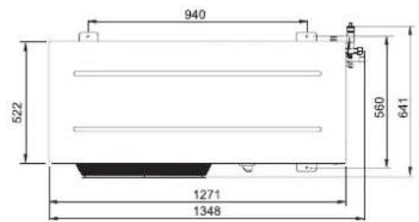
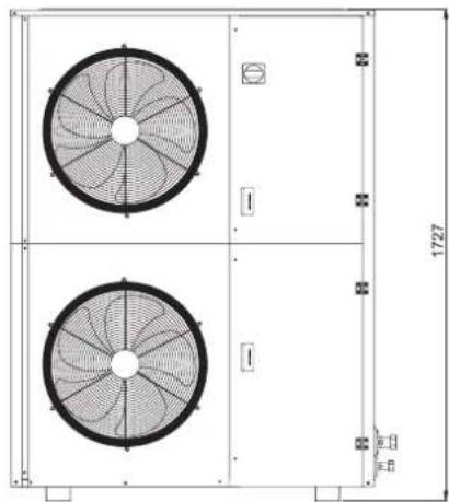
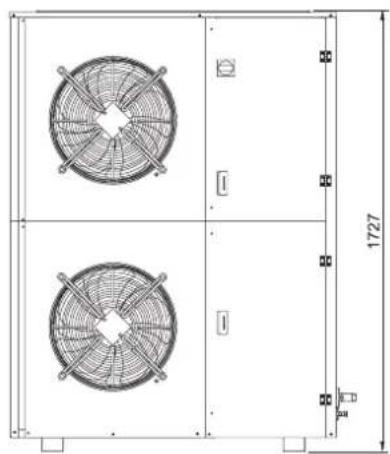
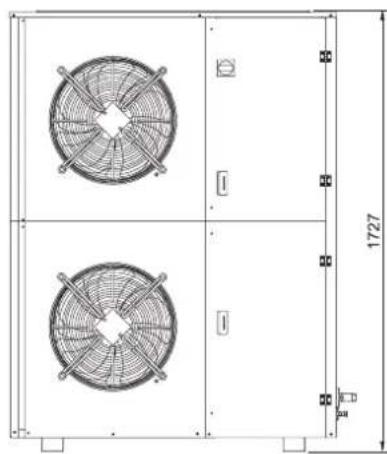
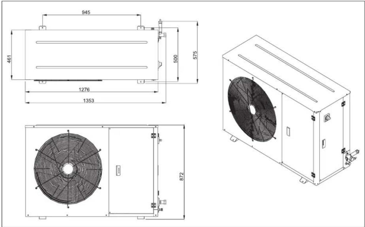
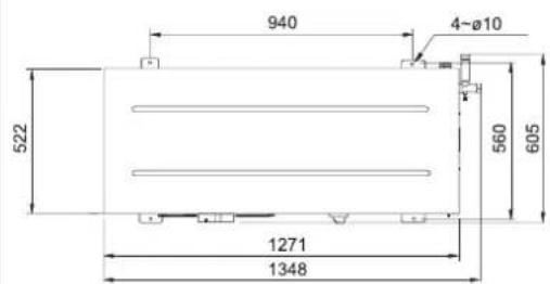
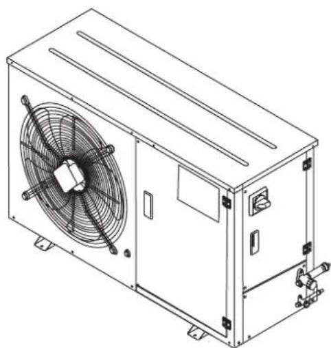
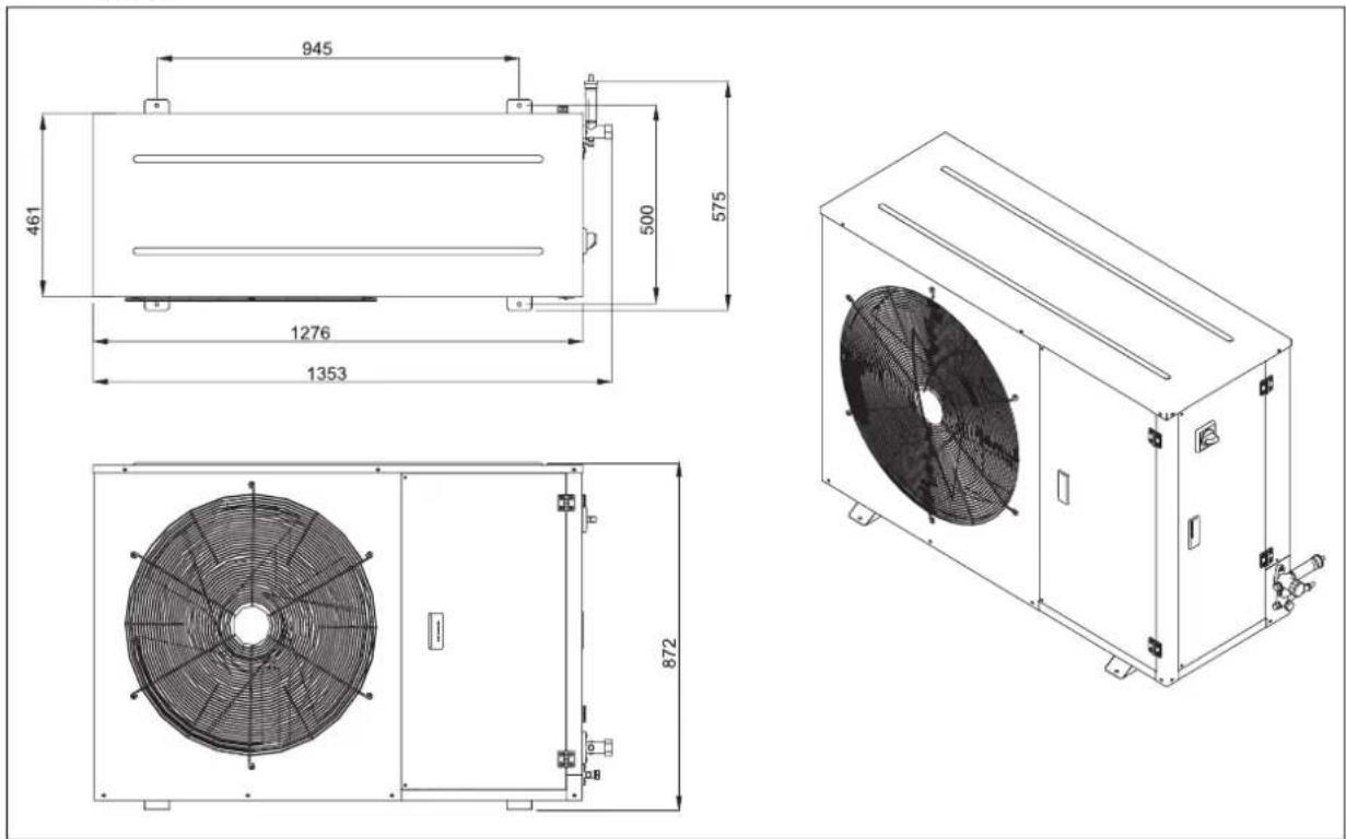
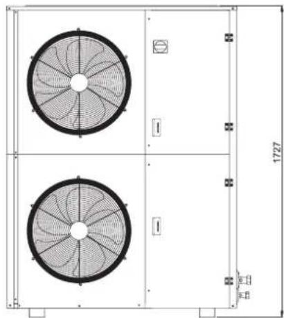
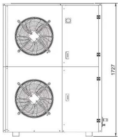
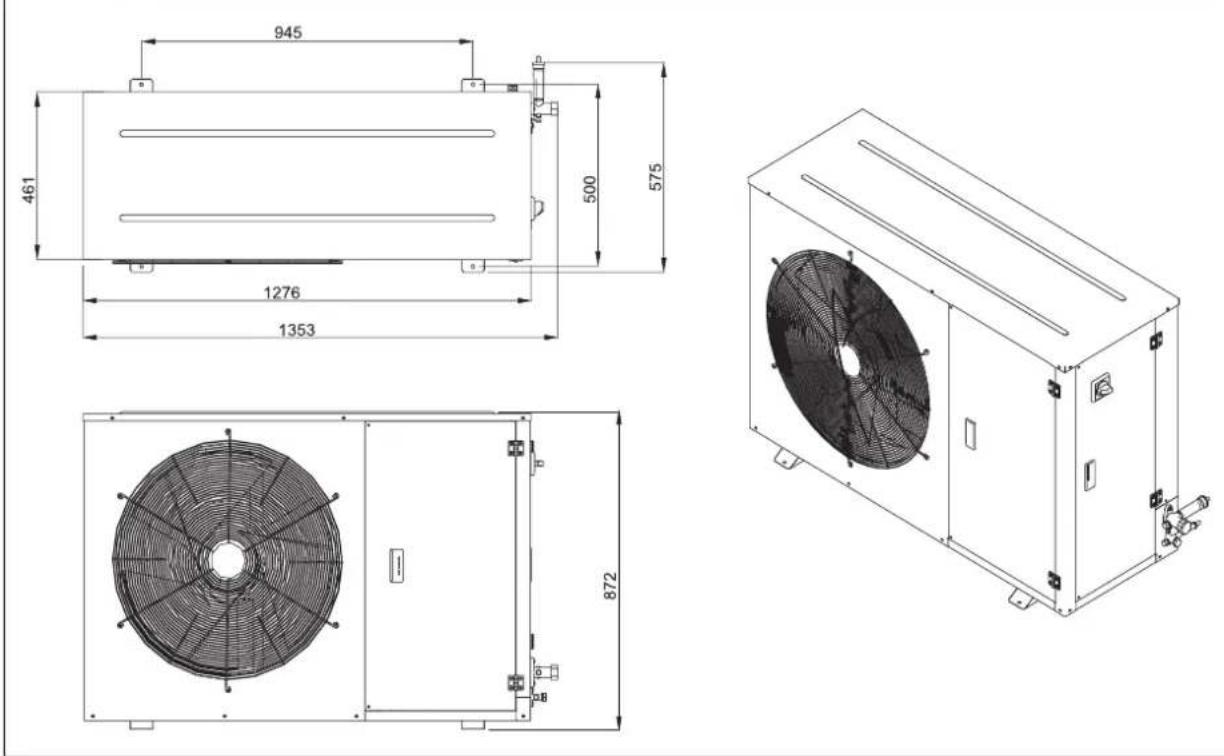
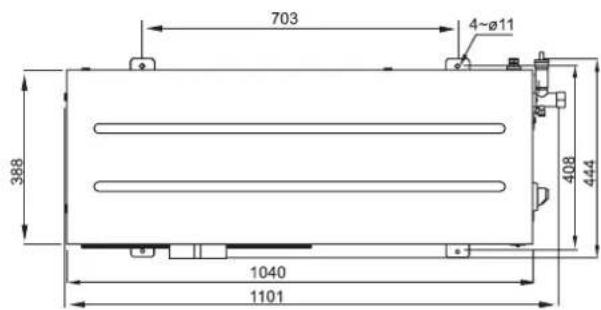
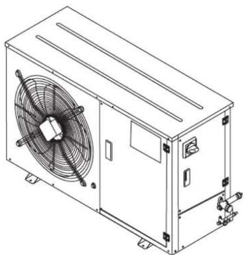
10. Outline drawings
Series 1
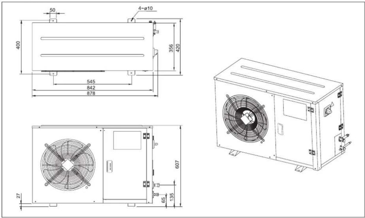
Series 2
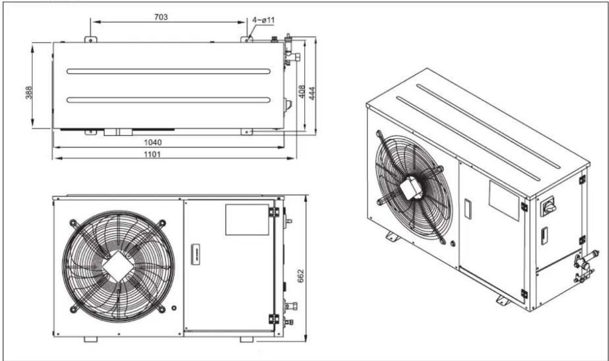
Series 3

Series 4
Medium Temperature
natural_image
Technical drawing of a dual fan assembly with mounting holes and dimension label (no text or symbols)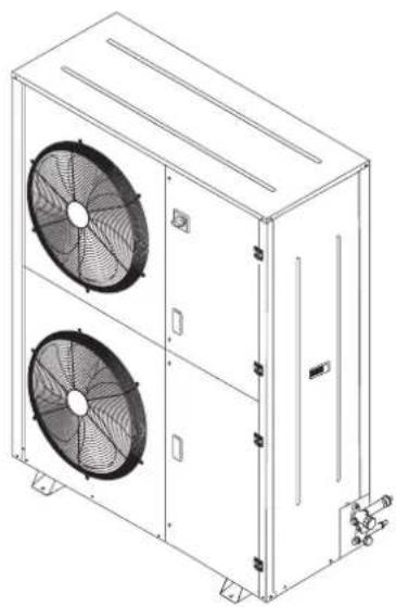
natural_image
Technical line drawing of a dual-panel air conditioning unit with fans and cooling fins (no text or symbols)Low Temperature
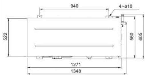
natural_image
Technical drawing of a dual-panel air fan assembly with dimension annotations (1727 and 800 mm) — no readable text or symbols beyond measurement markers.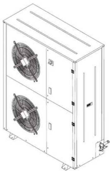
natural_image
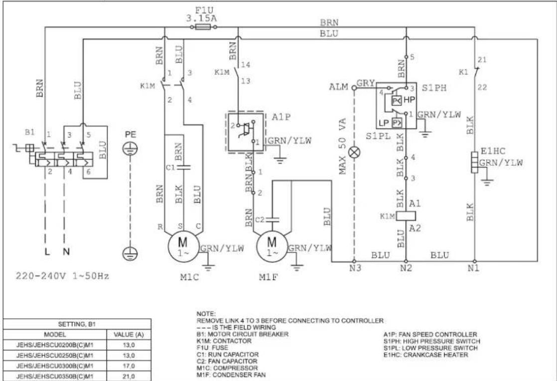
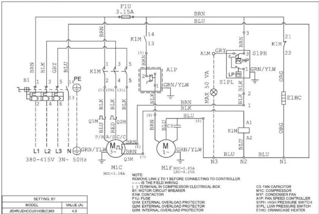
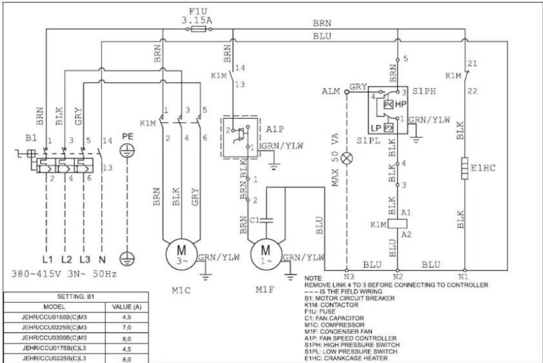
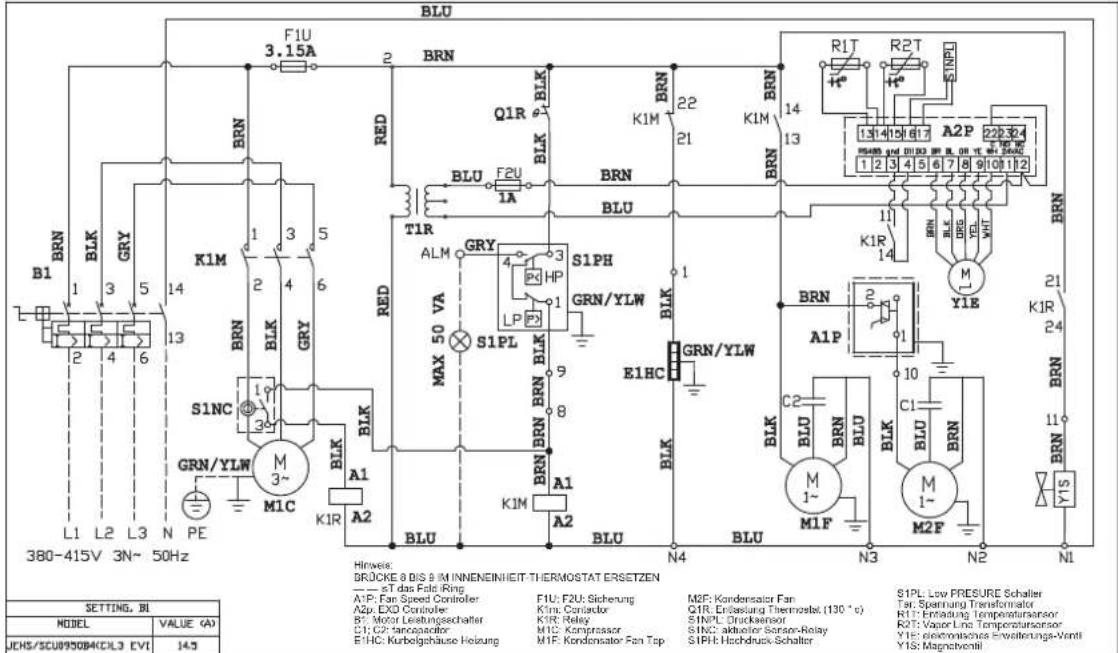
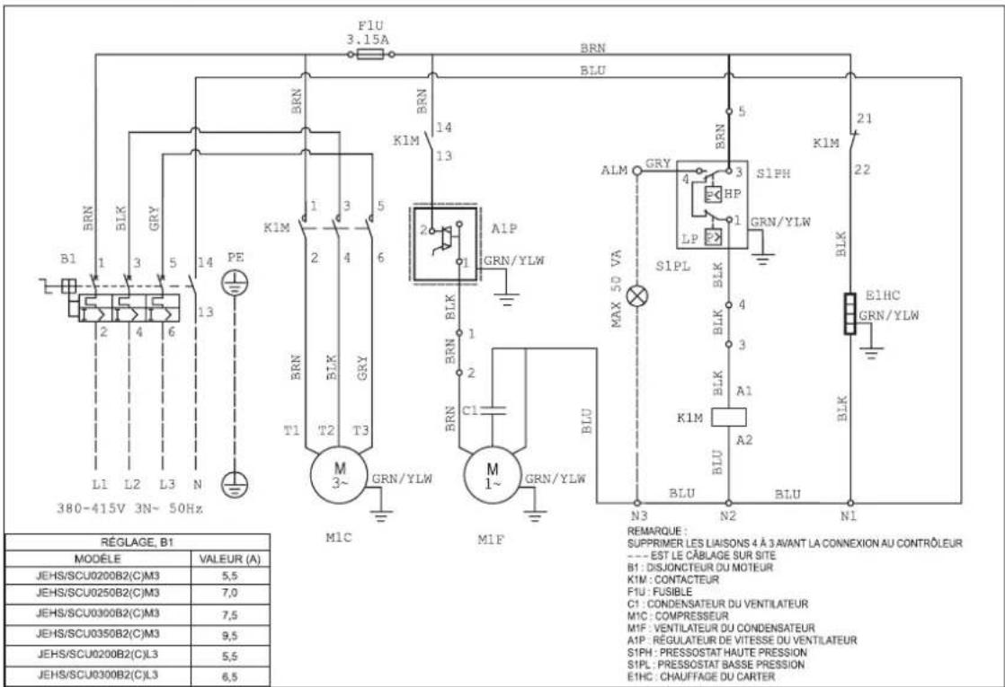
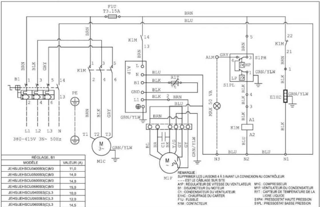
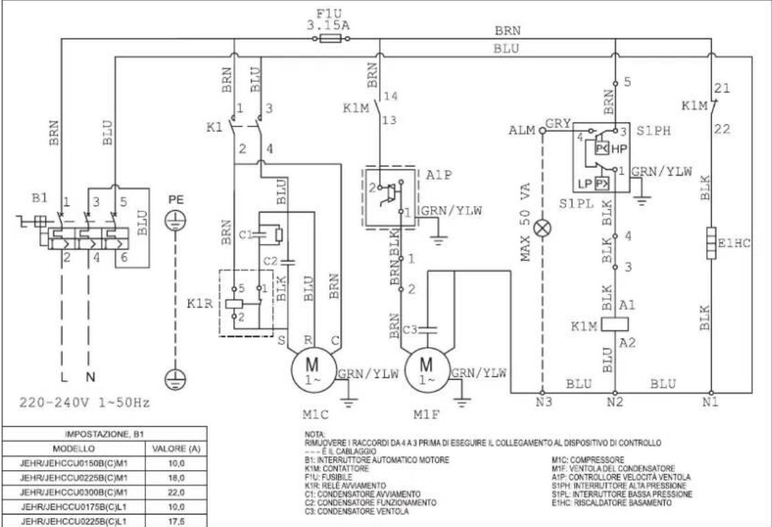
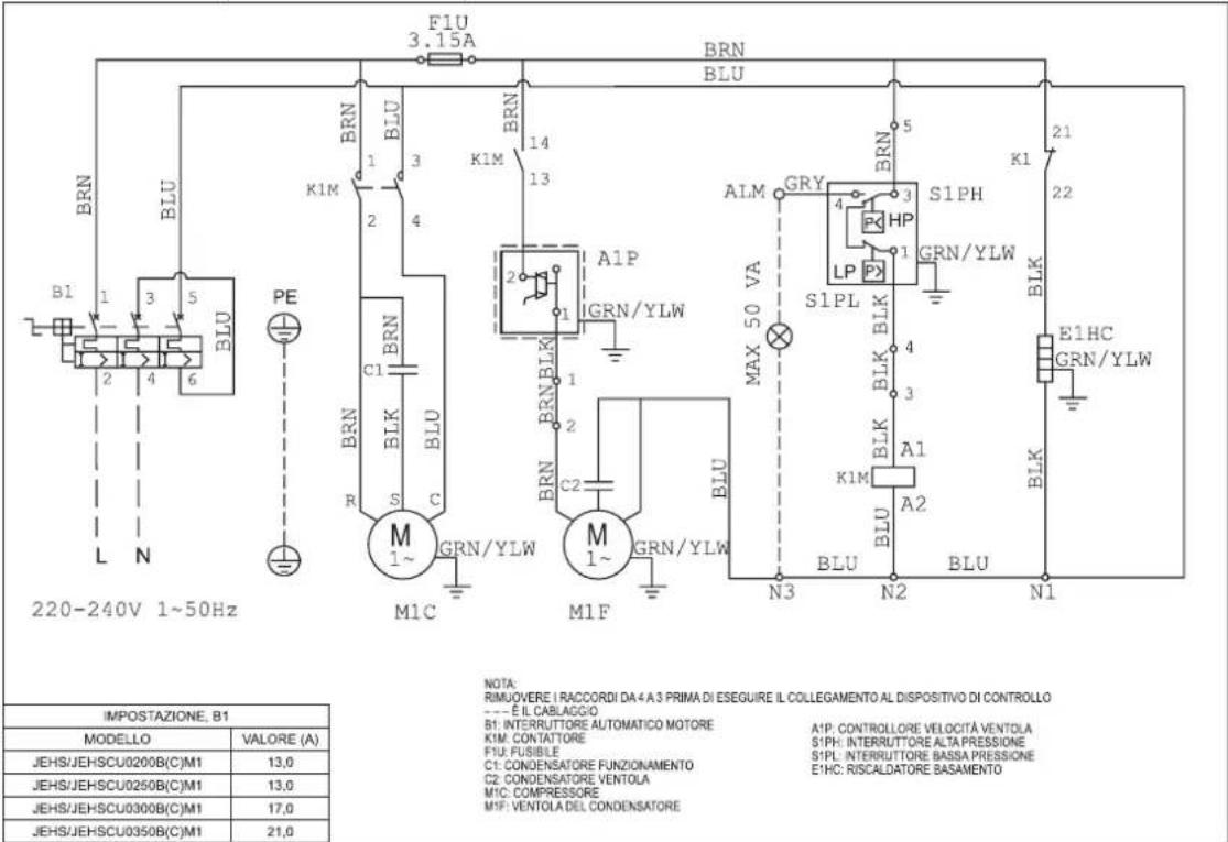
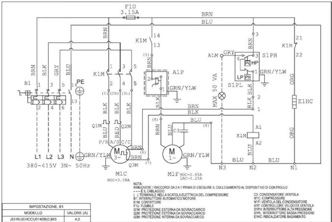
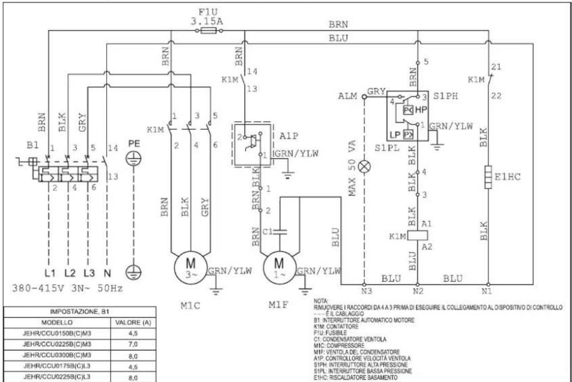
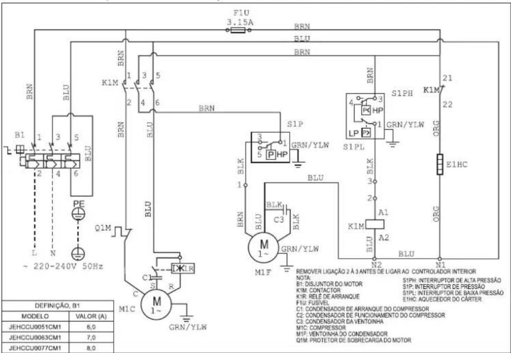
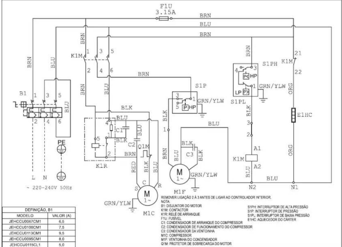
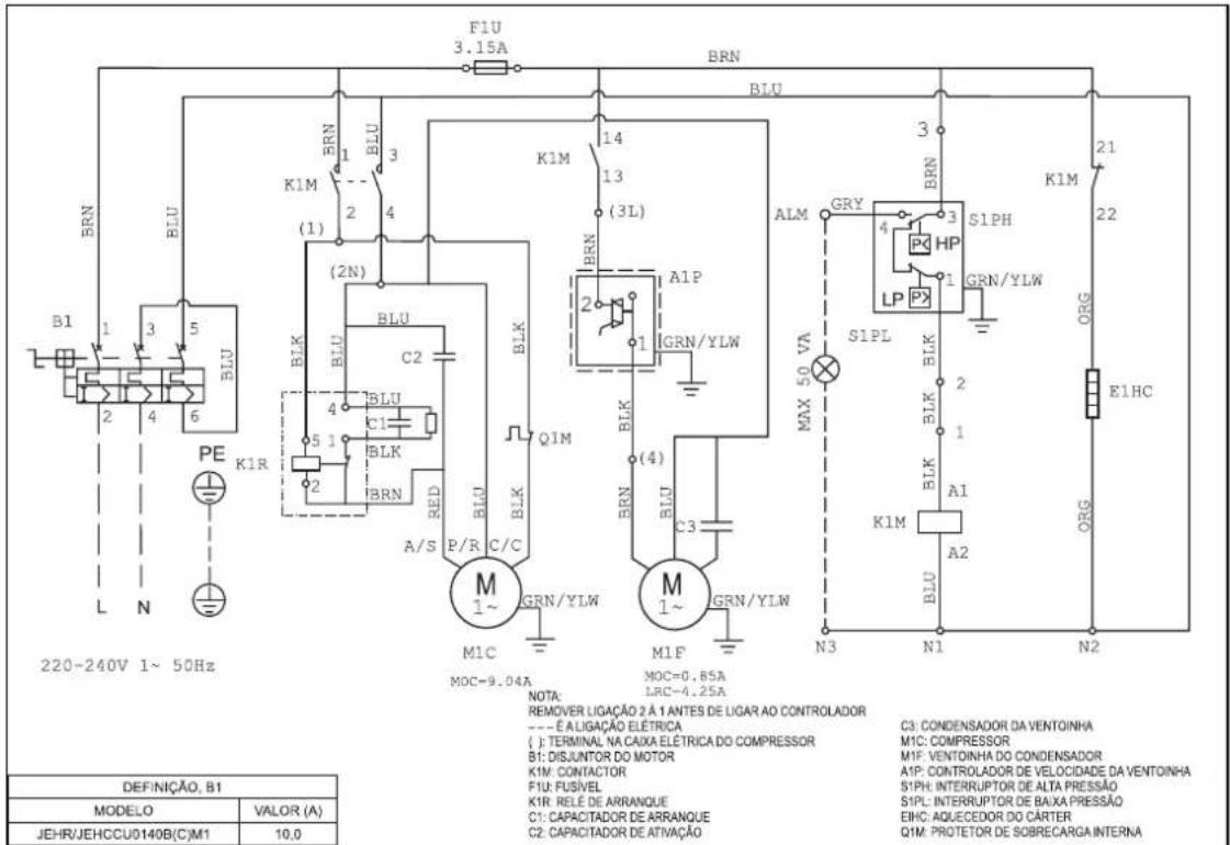
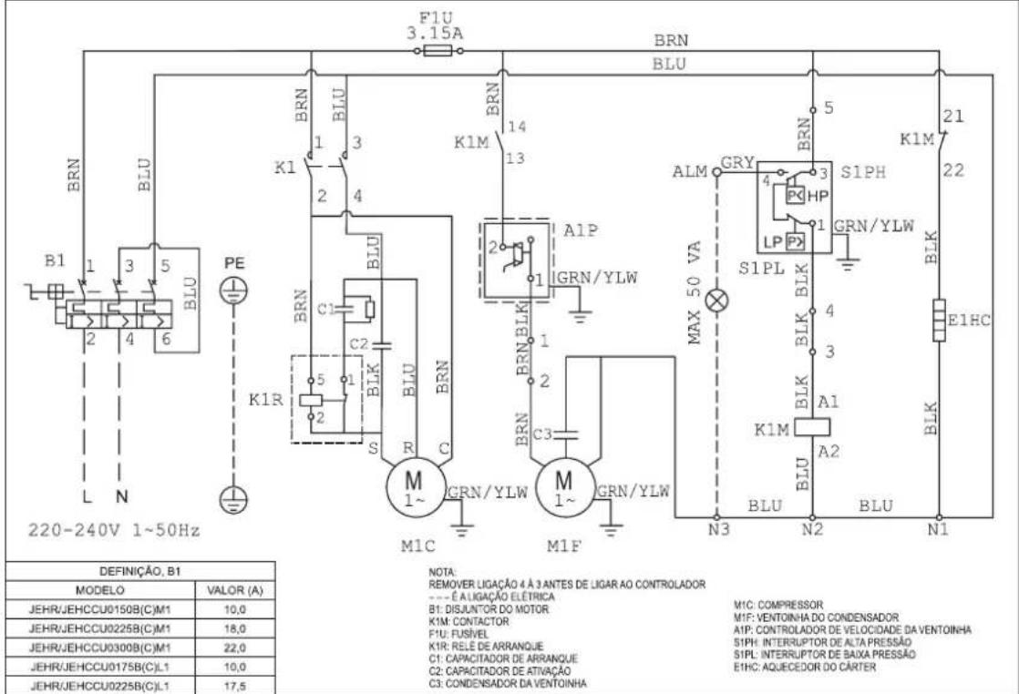
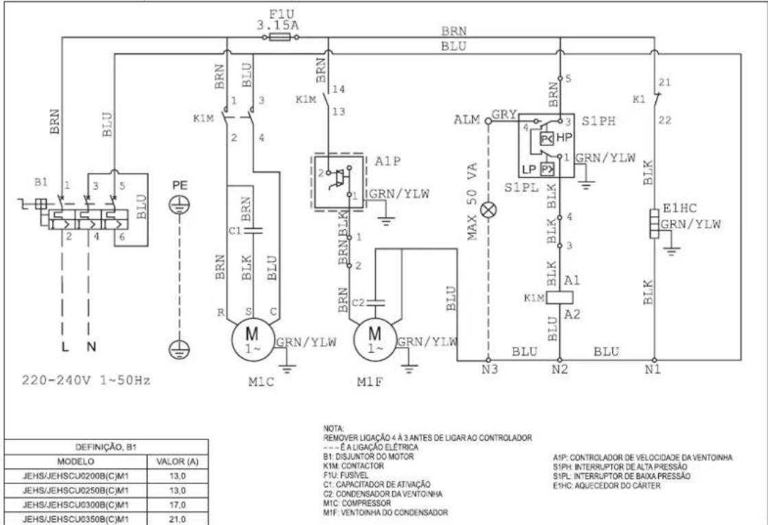
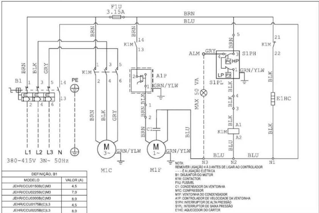
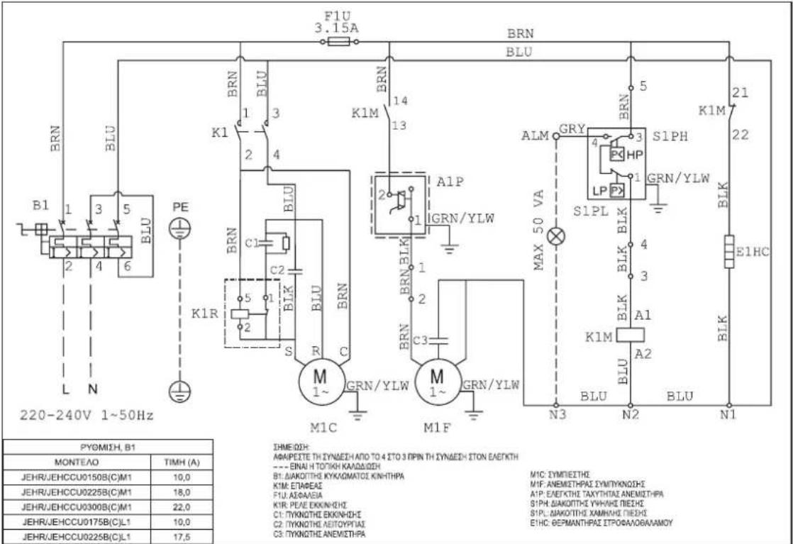
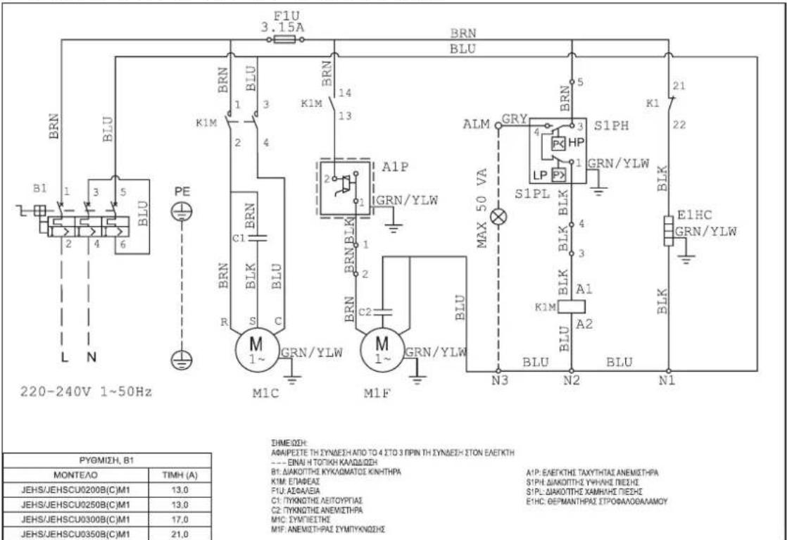
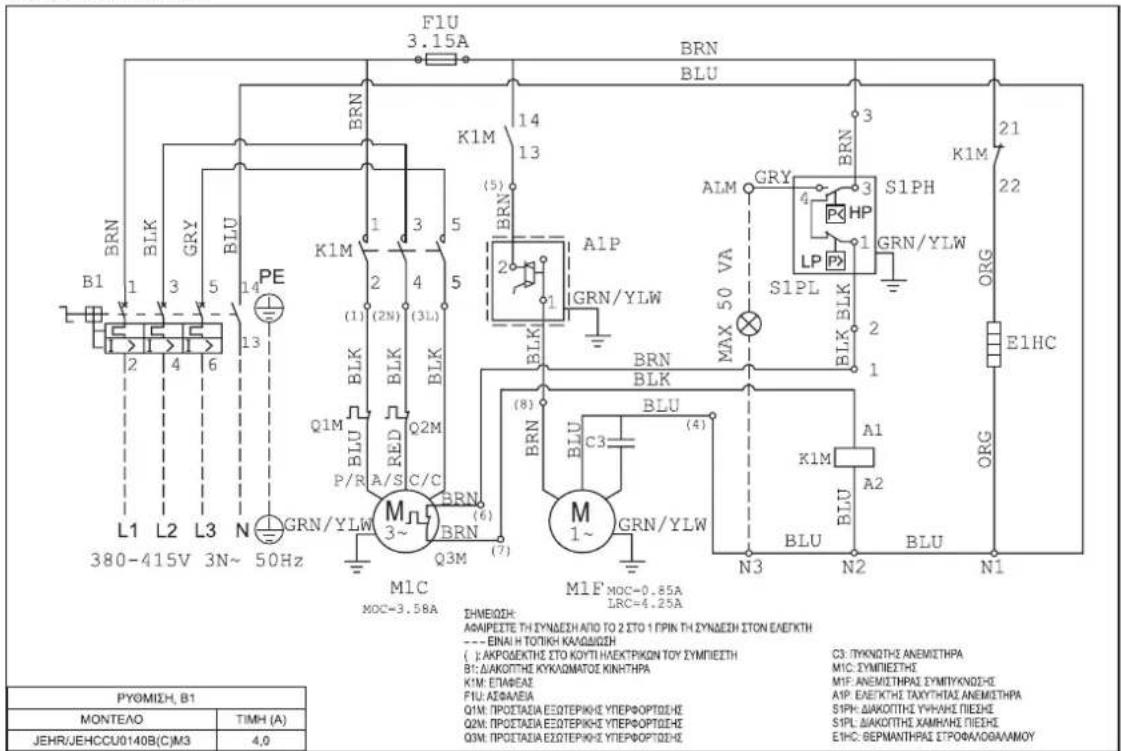
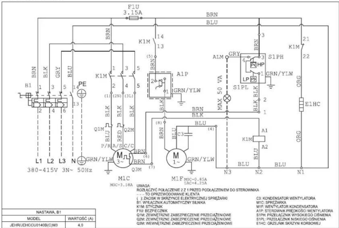
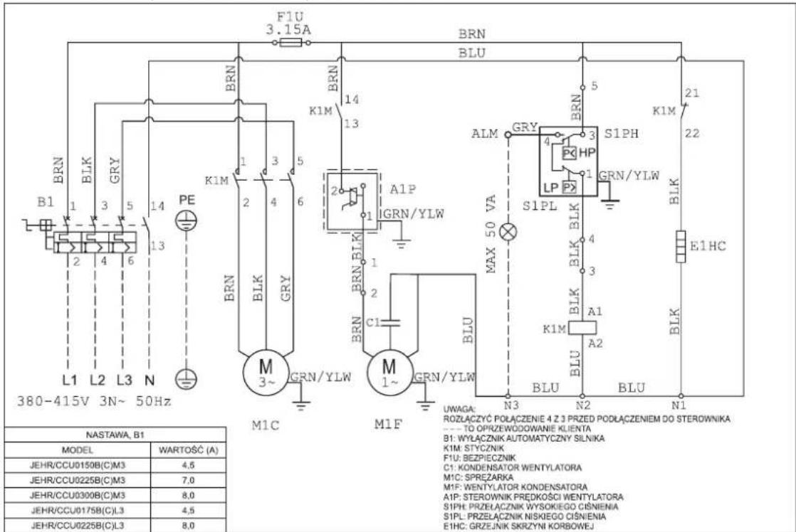
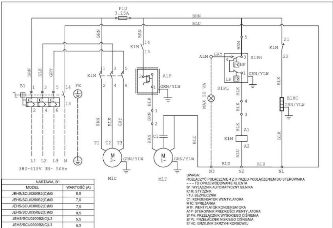
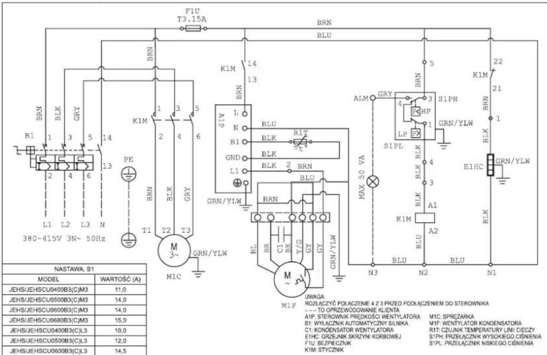
Technical line drawing of a dual-panel industrial cooling unit with two fans (no text or symbols)11. Electrical Data
Important Note: All wiring and connections to the condensing unit must be made in accordance to the local codes.
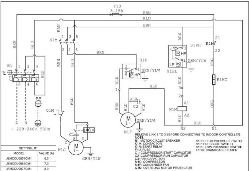
Single Phase
JEHCCU0040CM1; JEHCCU0050CM1
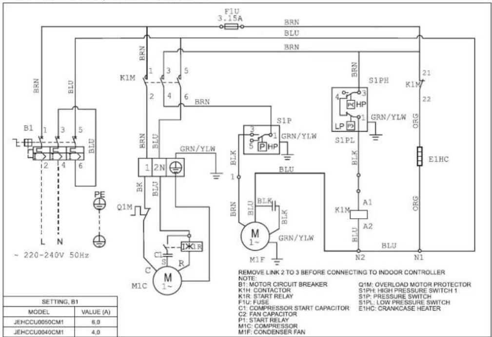
JEHCCU0051CM1; JEHCCU0063CM1; JEHCCU0077CM1
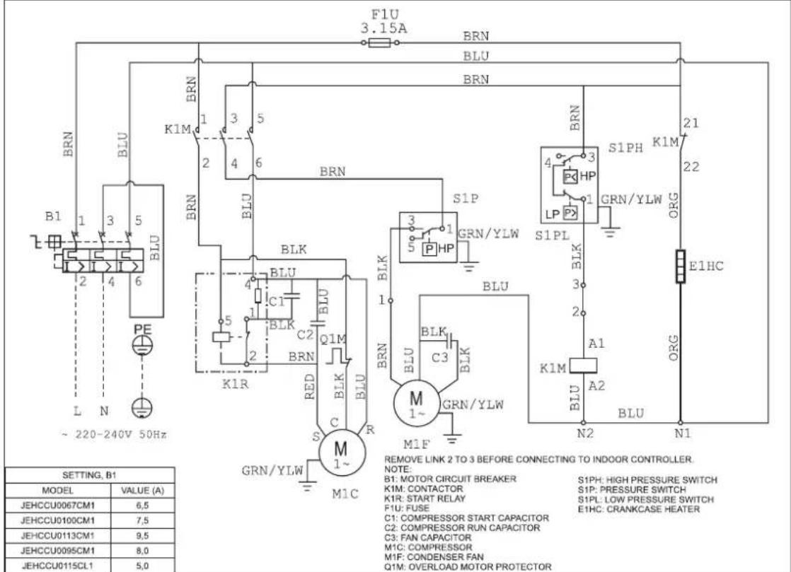
JEHCCU0067CM1; JEHCCU0095CM1; JEHCCU0100CM1; JEHCCU0113CM1, JEHCCU0115CL1
JEHCCU0140CM1
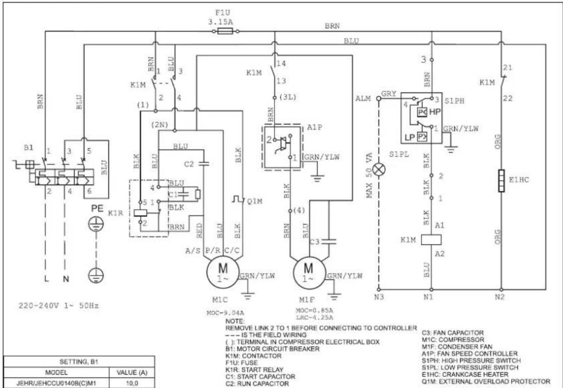
JEHCCU0150CM1, JEHCCU0225CM1, JEHCCU0300CM1
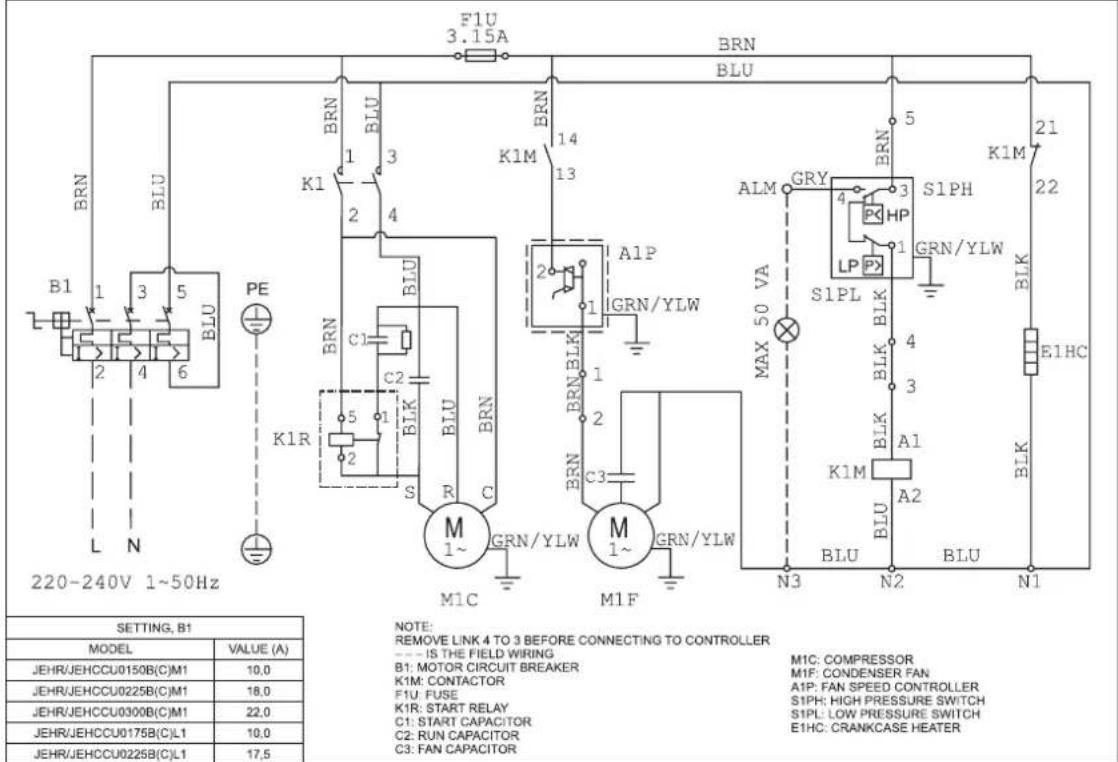
JEHSCU0200CM1, JEHSCU0250CM1, JEHSCU0300CM1
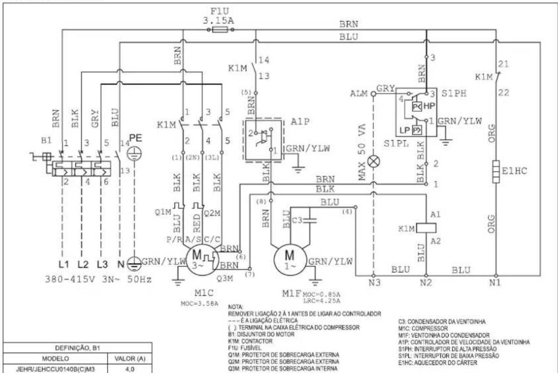
Three Phase
JEHCCU0140CM3
JEHCCU0150CM3, JEHCCU0225CM3, JEHCCU0300CM3
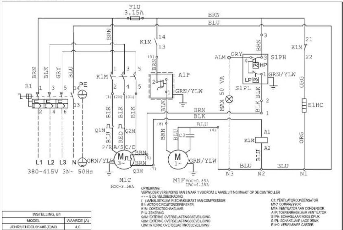
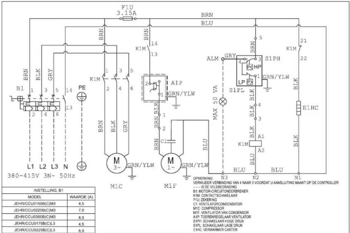
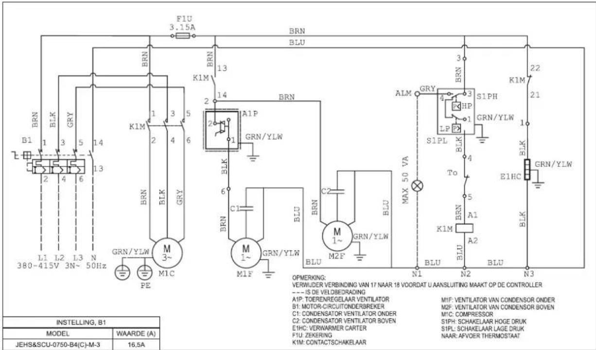
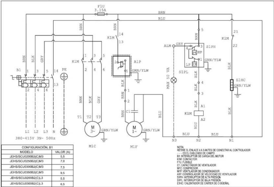
JEHSCU0200CM3, JEHSCU0250CM3, JEHSCU0300CM3, JEHSCU0350CM3, JEHSCU0200CL3, JEHSCU0300CL3
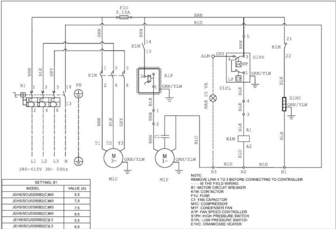
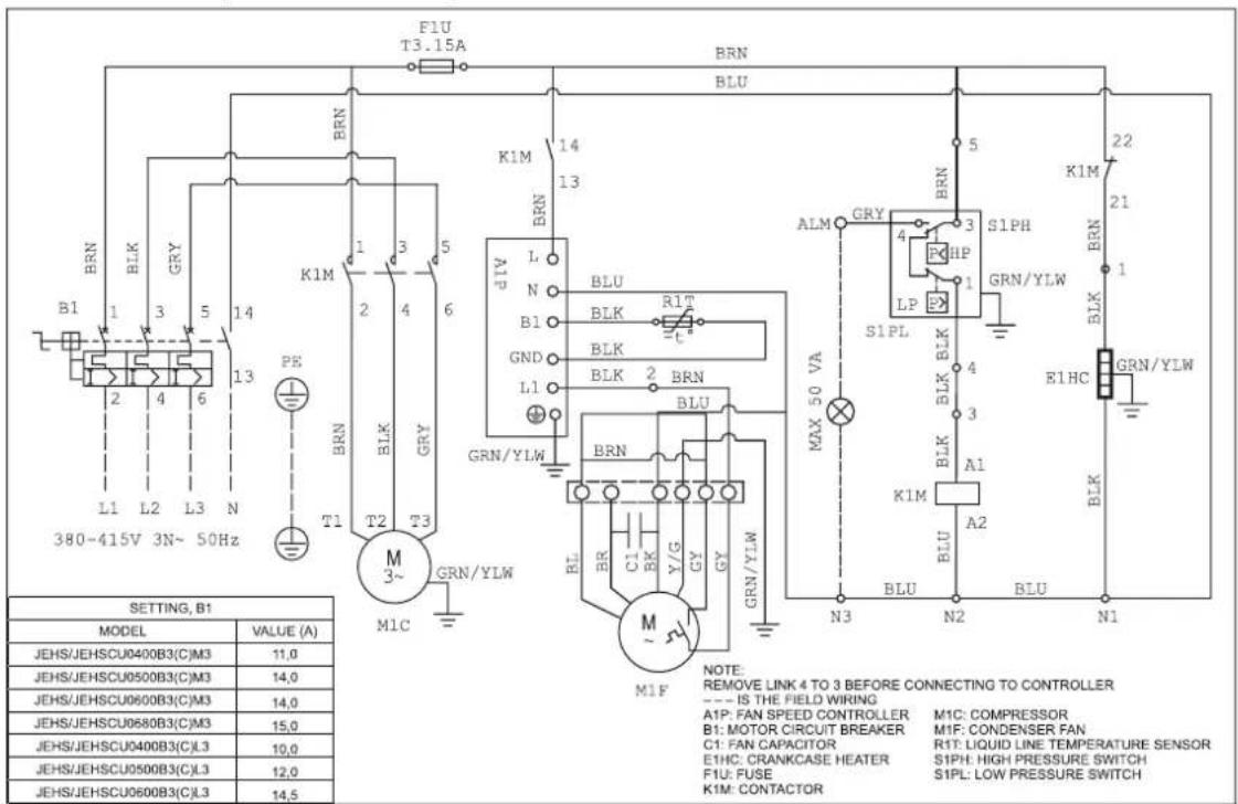
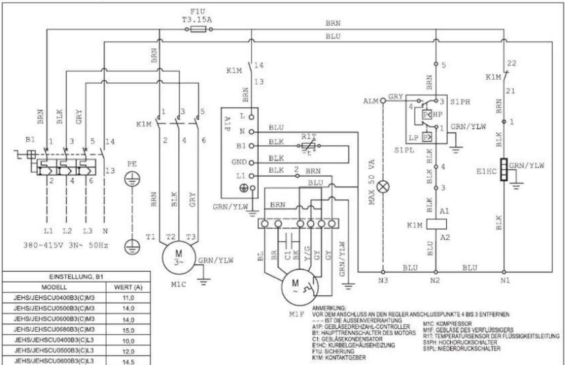
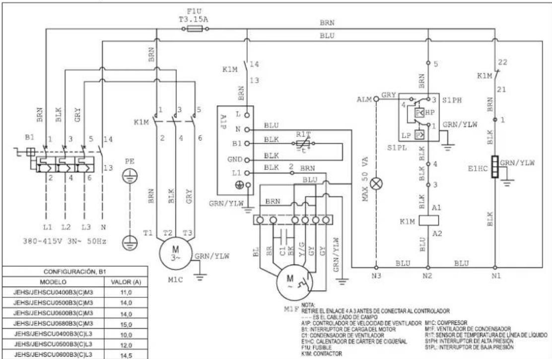
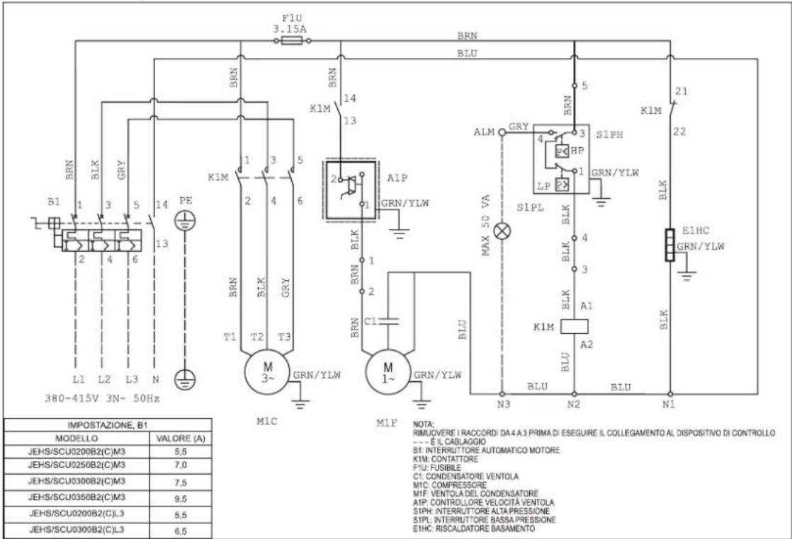
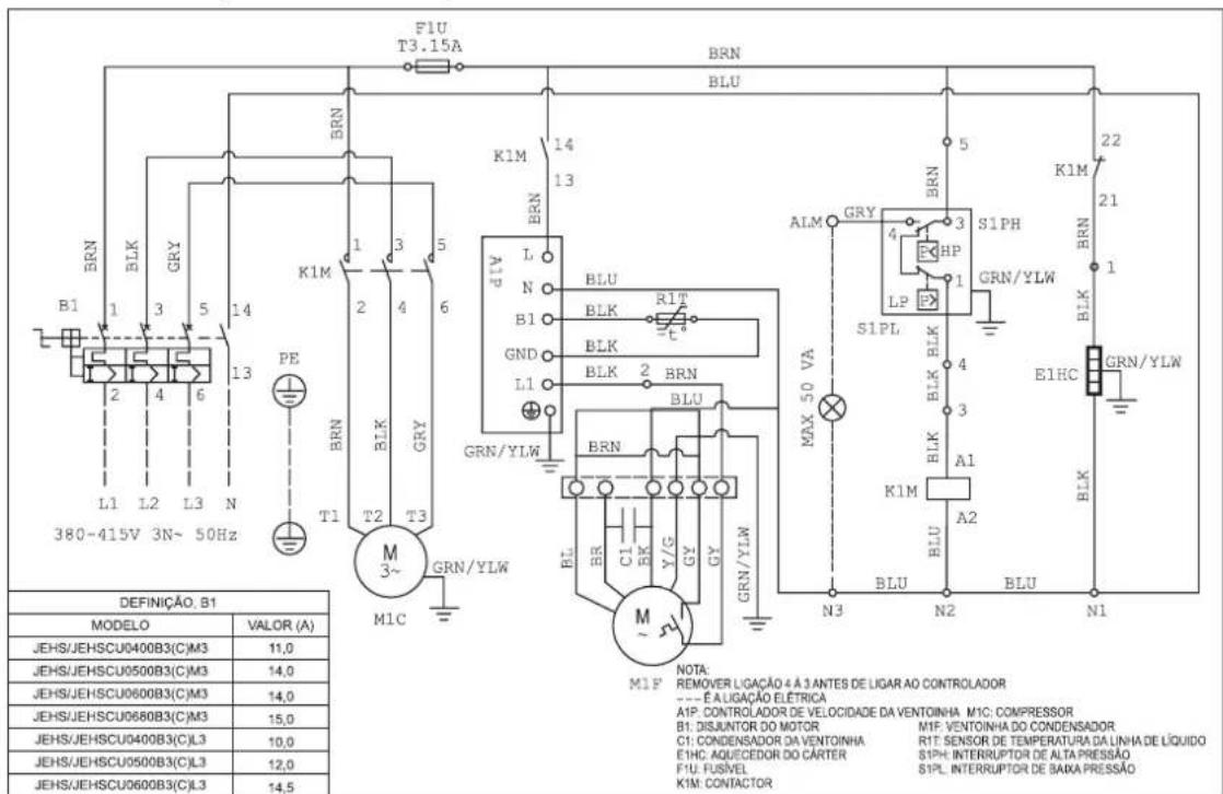
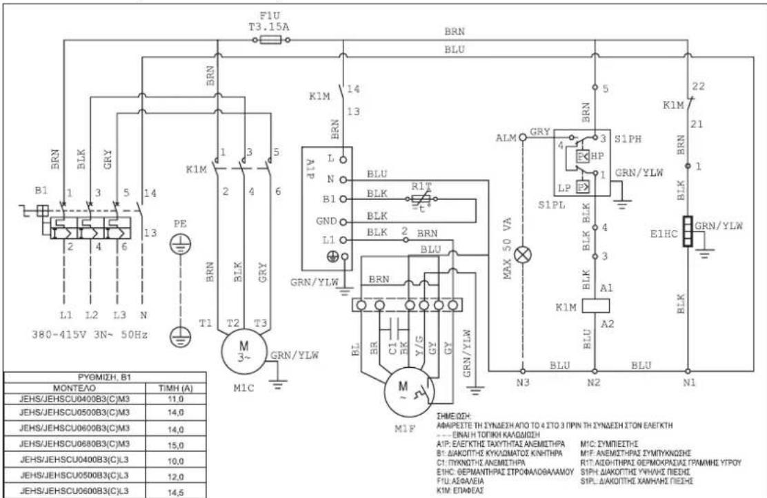
JEHSCU0400CM3, JEHSCU0500CM3, JEHSCU0600CM3, JEHSCU0680CM3, JEHSCU0400CL3, JEHSCU0500CL3, JEHSCU0600CL3
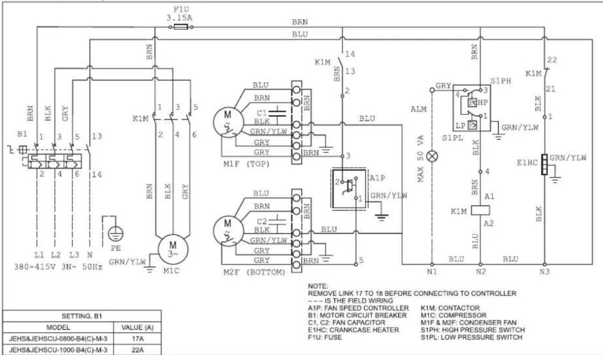
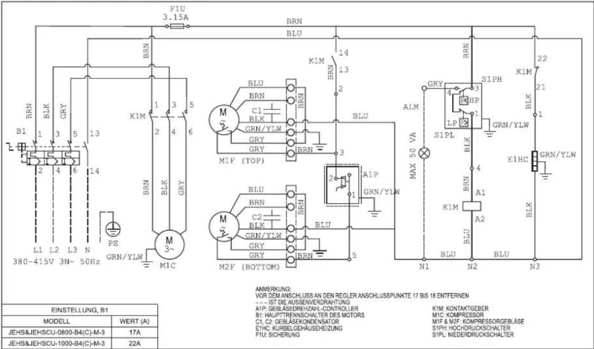
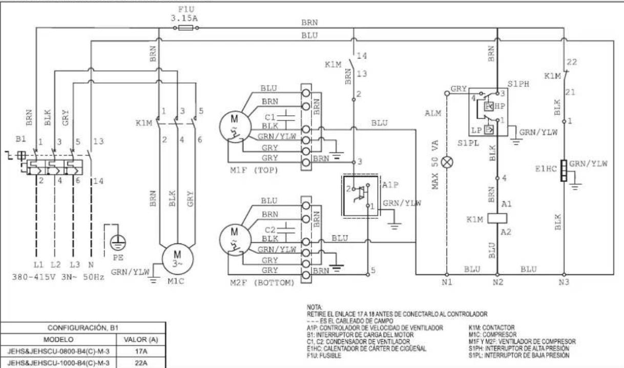
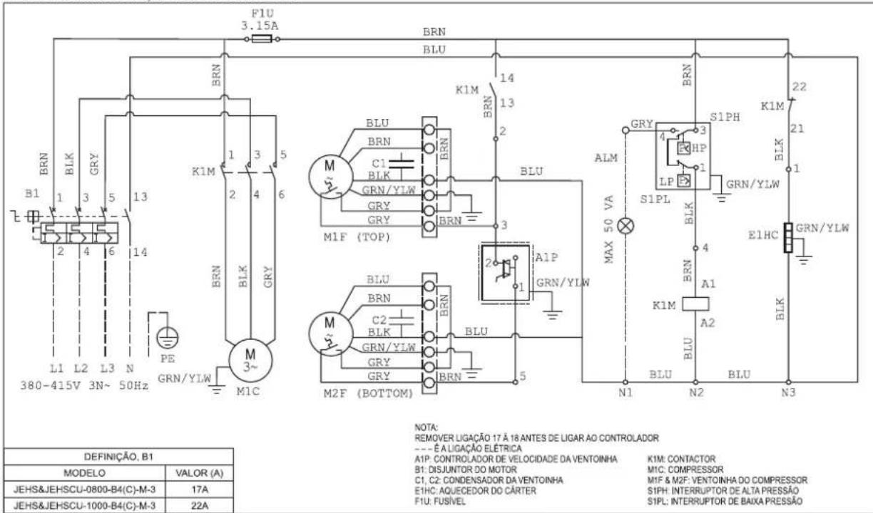
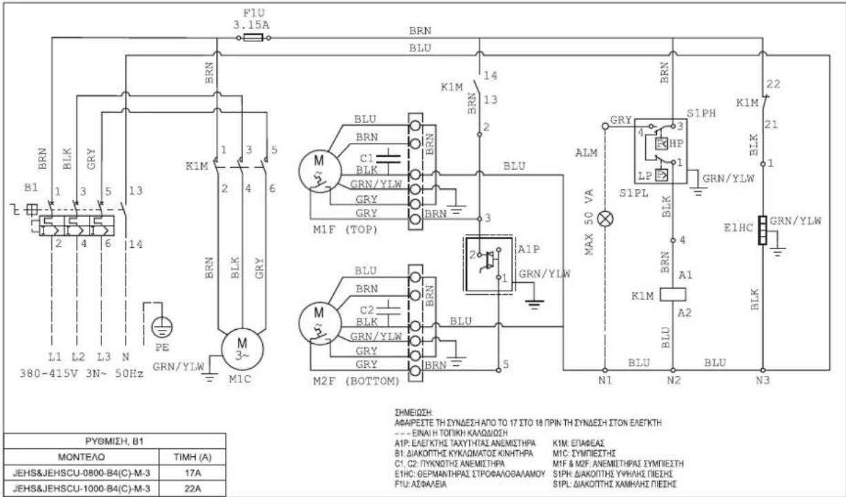
JEHSCU0800CM3, JEHSCU1000CM3
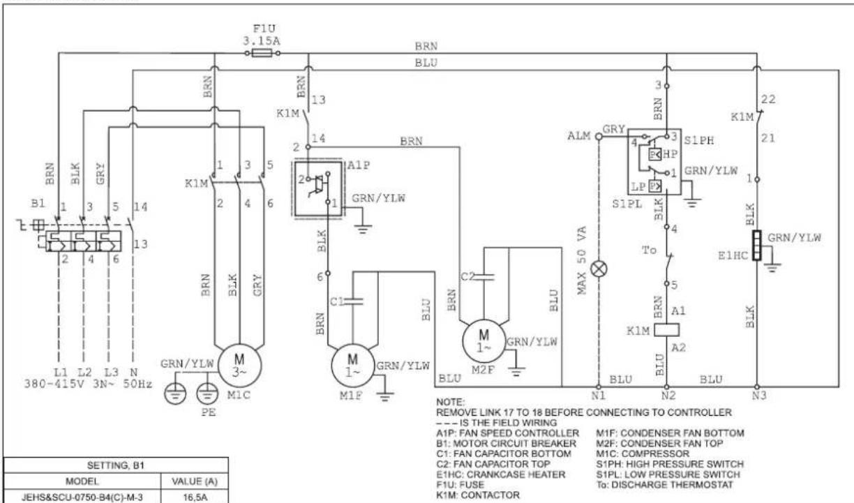
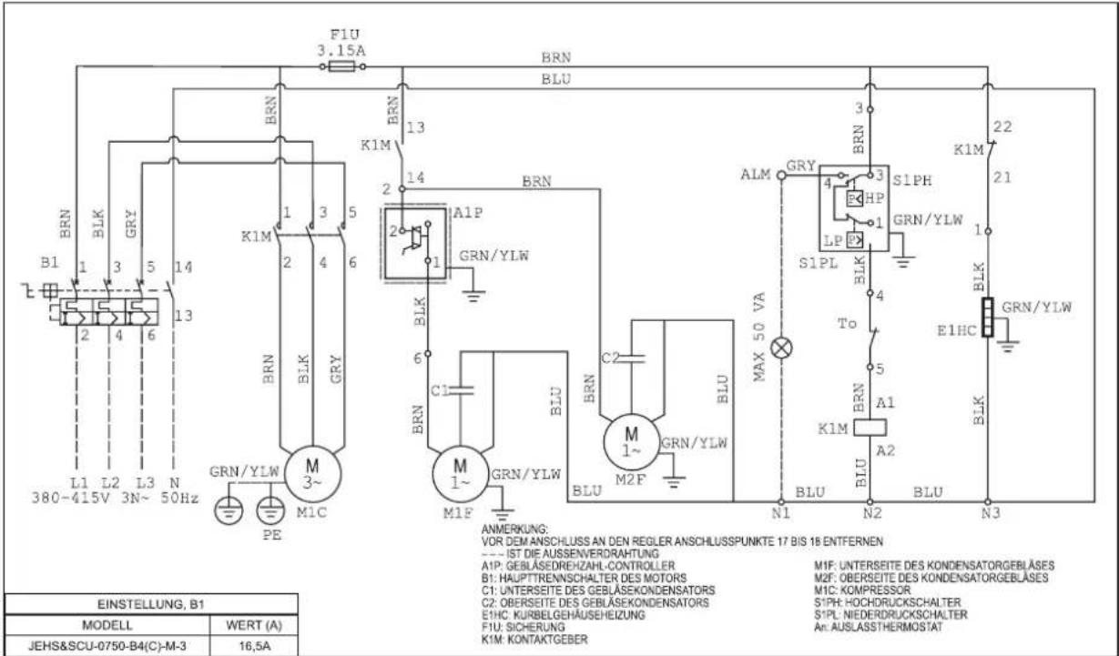
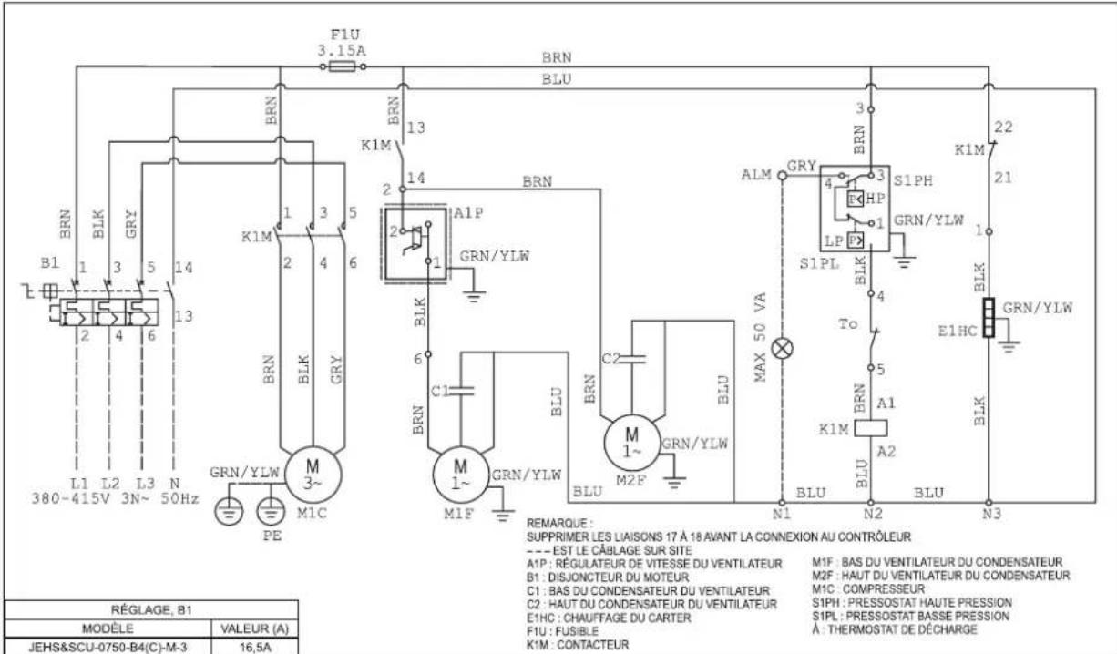
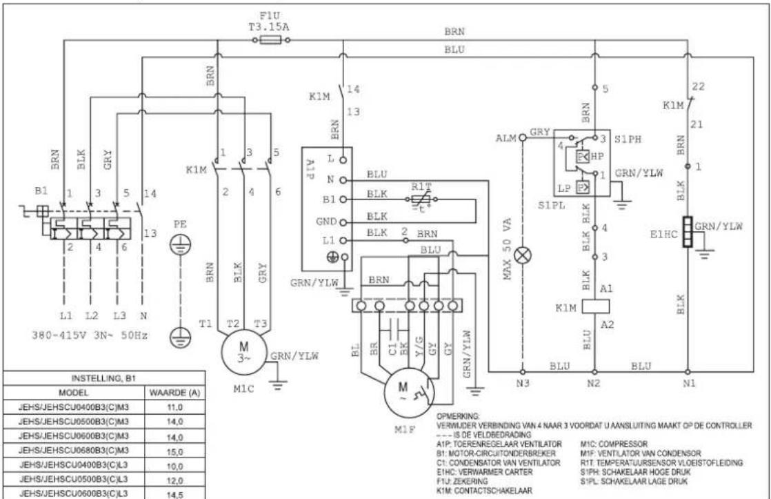
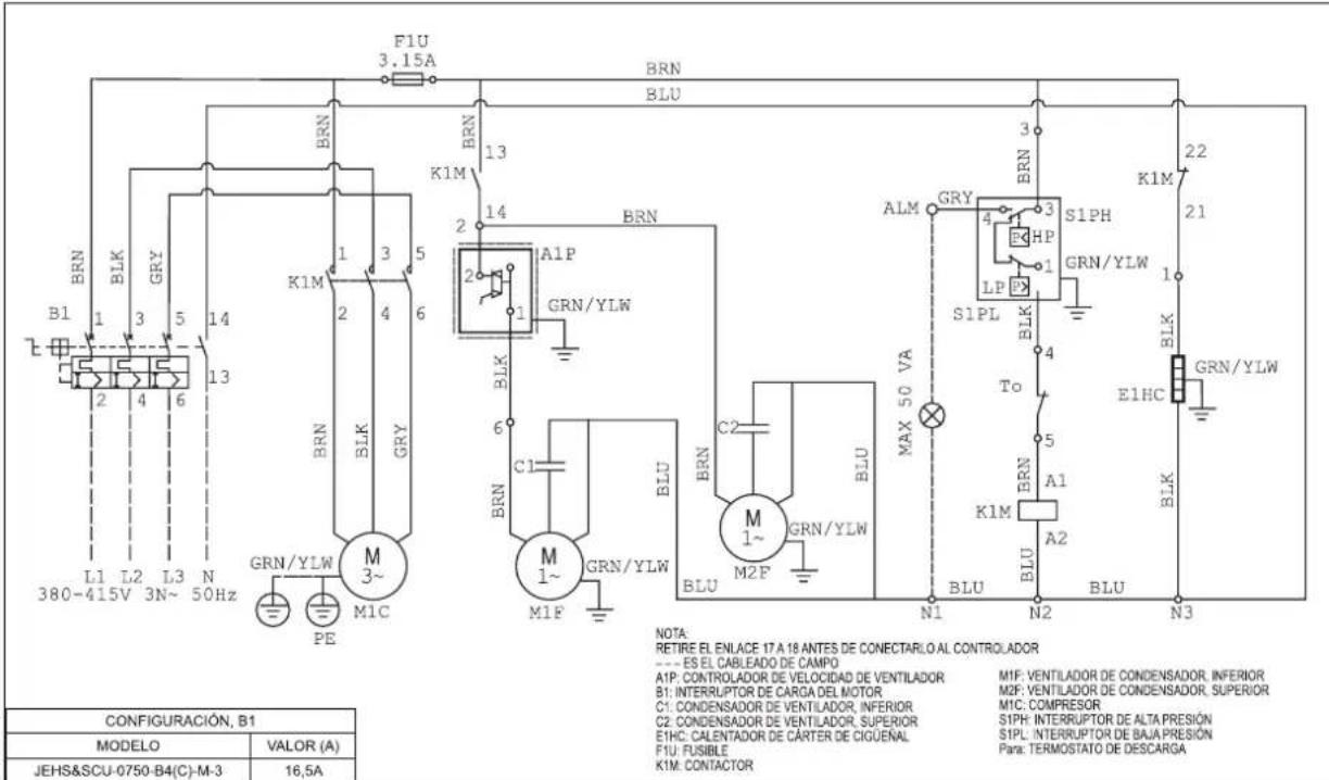
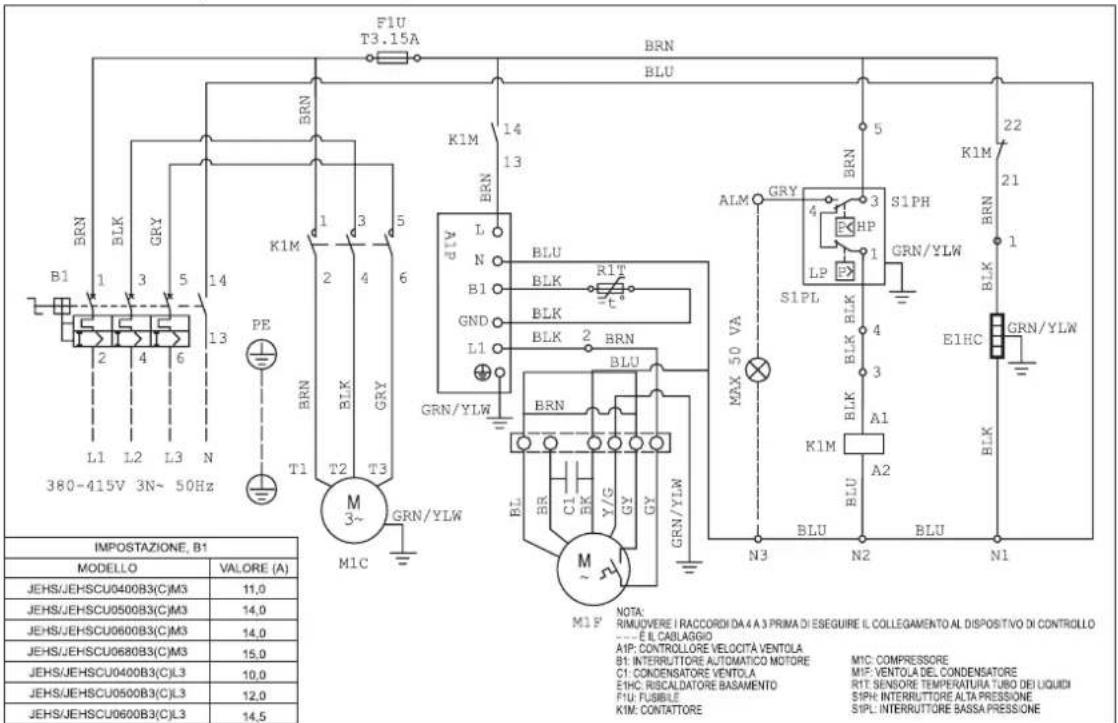
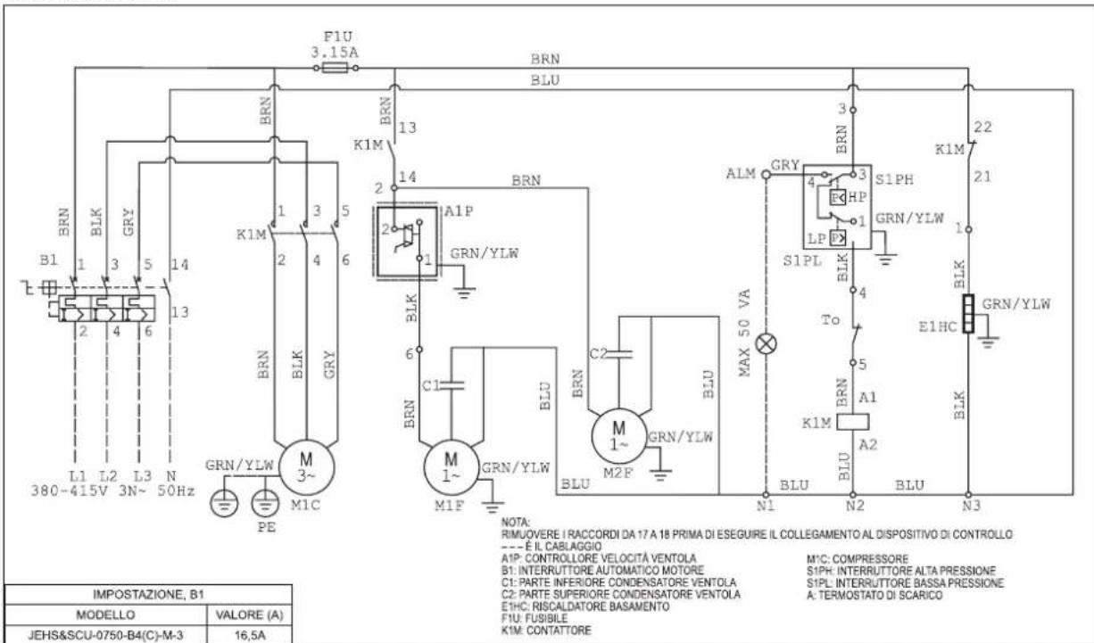
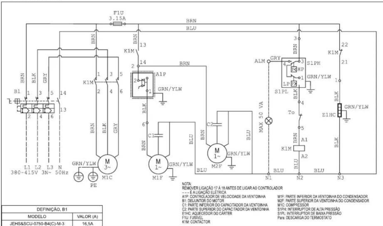
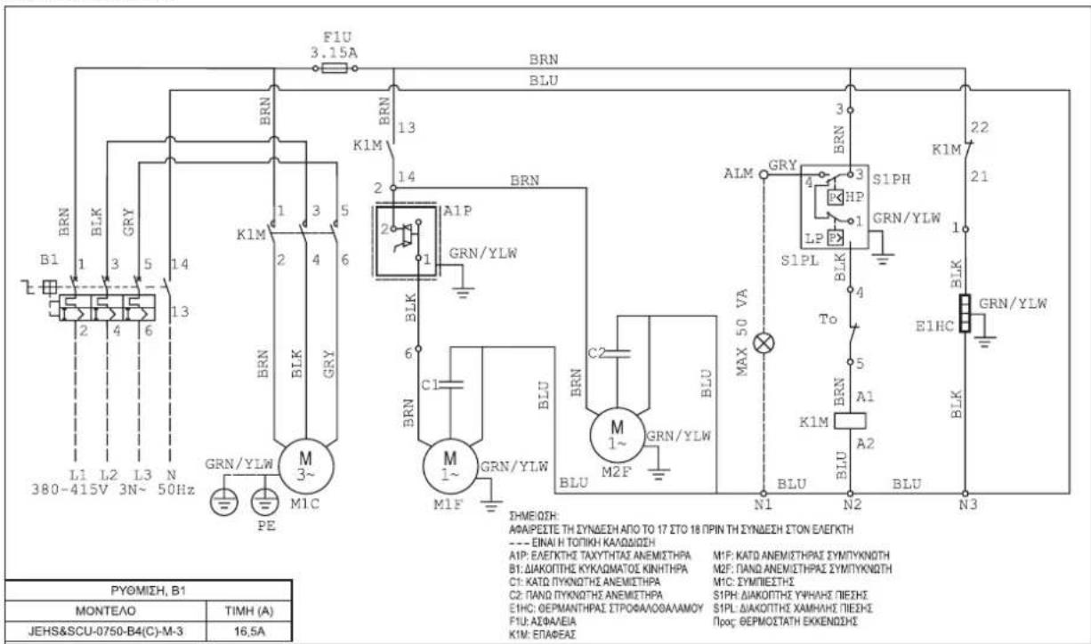
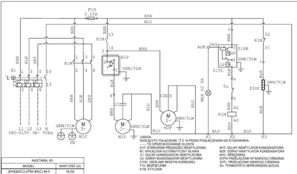
JEHSCU0750CL3
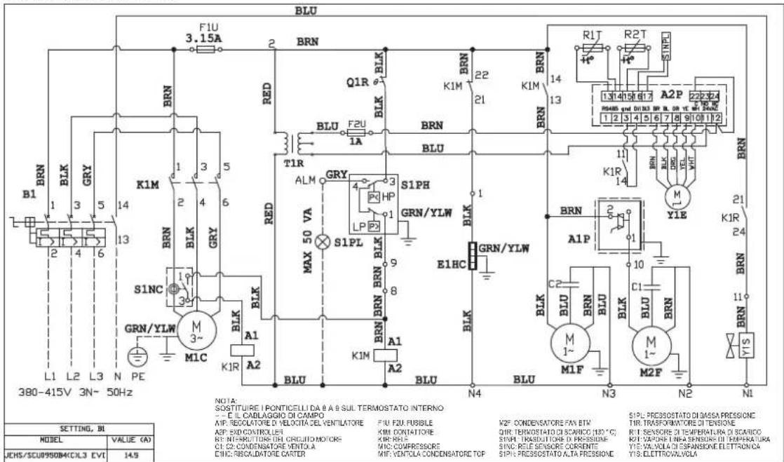
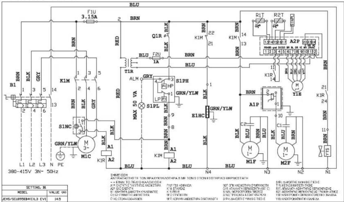
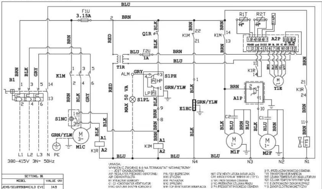
JEHSCU0950CL3 EVI
12. Appendix
CHECKLIST BEFORE START-UP
| No. | Description | Record |
| 1 | Is the unit in good condition and without any visible damage? | ☐ Yes |
| 2 | Has the unit been transported in upward position? | ☐ Yes |
| 3 | Is the crankcase oil level between 1/4 and 3/4 of the compressor sight glass? | ☐ Yes |
| 4 | Is the power supply on site in line with the unit specification? | ☐ Yes |
| 5 | Is air short circuit and/or air blockage avoided? | ☐ Yes |
| 6 | Is the location well ventilated? | ☐ Yes |
| 7 | Is there sufficient space for air flow and maintenance? | ☐ Yes |
| 8 | Is all the pre-charged nitrogen released before the field pipe connection started? | ☐ Yes |
| 9 | Has nitrogen been blown through the pipes during brazing? | ☐ Yes |
| 10 | Is there only 1 indoor unit connected to the CDU? | ☐ Yes |
| 11 | Does the field piping has the same diameter as the pipes coming from the CDU? | ☐ Yes |
| 12 | Is the suction pipe insulated? | ☐ Yes |
| 13 | Does the bends have enough bending radius? | ☐ Yes |
| 14 | Is the total pipe length less than 25 m? | ☐ Yes |
| 15 | Is the height difference within the specifications? [Refer page 7] | ☐ Yes |
| 16 | Are the oil traps in the vertical suction line correctly positioned? [Refer page 3] | ☐ Yes |
| 17 | Does the CDU capacity matches the indoor unit capacity? | ☐ Yes |
| 18 | Does the TXV capacity matches the indoor unit capacity? | ☐ Yes |
| 19 | Is the TXV sensing bulb fixing in good position/condition? | ☐ Yes |
| 20 | Is there a MOP expansion valve installed? [Refer page 3] | ☐ Yes |
| 21 | Was inert, dry gas (e.g. Nitrogen) used when pressure testing? | ☐ Yes |
| 22 | Could the leak test pressures be reached? | ☐ Yes |
| 23 | Did the test pressure stayed stable after at least 24 hours? | ☐ Yes |
| 24 | Could the vacuum condition (< -0.1 barg for 2 hours) be reached? | ☐ Yes |
| 25 | Did the pressure stayed stable for at least 1 hour, when turning off the vacuum pump? | ☐ Yes |
| 26 | Is the high/low pressure safety on the pressure switch set correctly? [Refer page 4] | ☐ Yes |
| 27 | Is the fan speed controller set correctly? [Refer page 4] | ☐ Yes |
| 28 | Is the correct circuit breaker been used? | ☐ Yes |
| 29 | Is there an earth connection foreseen? | ☐ Yes |
| 30 | Are all terminal connections good/tight connected? | ☐ Yes |
| 31 | Is the crankcase heater been energized for minimum 12 hours before start up? | ☐ Yes |
| 32 | Is the refrigerant correct for intended use? | ☐ Yes |
| 33 | Is the high pressure above the minimum limit when charging the system? [Refer page 5] | ☐ Yes |
| 34 | Is the refrigerant charge amount correct (clear sight glass)? | ☐ Yes |
Remarks: The system may only be started up if all questions can be answered with "Yes".
CHECKLIST BEFORE COMMISSIONING
| No. | Description | Record |
| 1 | Is the suction pressure decreasing and the discharge pressure increasing? | ☐ Yes |
| 2 | Is the compressor rotation (only for scroll type) correct (no abnormal noise)? | ☐ Yes |
| 3 | Is the crankcase oil level between 1/4 and 3/4 of the compressor sight glass? (after 3 or 4 hours of operation) | ☐ Yes |
| 4 | Is the discharge temperature within the limits (between 50 °C and 90 °C)? | ☐ Yes |
| 5 | Is the suction superheat within the limits (between 5K and 20K) during normal operation? | ☐ Yes |
| 6 | Is the suction superheat within the limits (between 5K and 20K) after defrost operation? | ☐ Yes |
| 7 | Is the running current below isolator setting value? | ☐ Yes |
| 8 | Is warm air blowing out from the condenser fan? | ☐ Yes |
| 9 | Is the compressor On/Off cycle within the specification? [Refer page 4] | ☐ Yes |
Remarks: The system may only be handed over to user/owner if all questions can be answered with "Yes".
Additional advice:
- Do not leave the system unattended until the system has reached its normal operating condition and the oil charge has properly adjusted itself to maintain the proper level in the sight glass.
- Check periodically the compressor performance and all the moving components during the first day of operation.
- Check the liquid line sight glass and expansion valve operation. If there is an indication that the system is low on refrigerant, thoroughly check the system for leaks before adding refrigerant.
SITE RECORDINGS
| Customer name | : | Field Settings | |
| Installer name | : | Pressure switch settings | : |
| Installation date | : | Cut Out (High Side) | : |
| Cut In (Low Side) | : | ||
| Unit model name | : | Differential (Low Side) | : |
| Unit serial number | : | ||
| Fan speed controller setting | : | ||
| Indoor unit | : | ||
| Expansion valve | : | Running conditions | |
| Discharge temperature | : | ||
| Refrigerant type | : | Suction superheat normal operation | : |
| Ambient temp. | : | Minimum suction superheat after defrost operation | : |
| Thermostat setting | : | ||
| Running current before defrost | : | ||
| Unit location/Field piping | Running current after defrost | : | |
| Piping length | : | Suction pressure (Pe) | : |
| Position of CDU | :Above/below indoor unit | Liquid line pressure (Pc) | : |
| Height difference | : | ||

Installationshandbuch
Bedienungsanleitung
natural_image
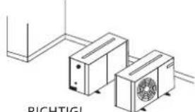
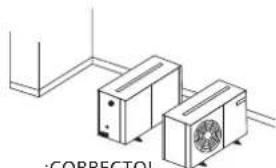
Diagram of two air conditioning units with fan blades, connected by lines (no text or symbols)FALSCH!
natural_image
Technical line drawing of two air conditioning units connected by a pipe, labeled 'RICHITIGI' below (no other text or symbols)RICHTIG!
At condition of Te -35°C, Ta +32°C
Refrigerant R404A
$$ = 3. 7 0 7 \mathrm{kW} $$
natural_image
Technical drawing of a dual fan assembly with mounting holes and dimension label (no text or symbols)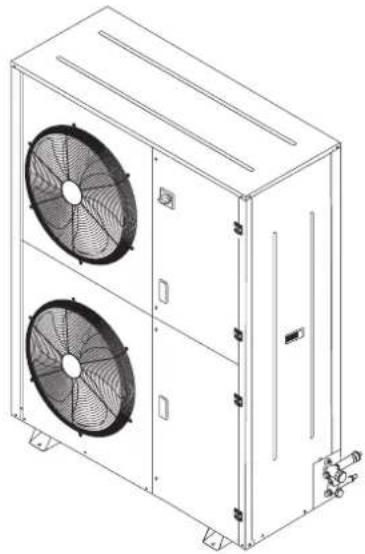
natural_image
Technical line drawing of a multi-level industrial air conditioning unit with two fans (no text or symbols)Niedrige Temperatur

natural_image
Technical drawing of a dual-panel air fan assembly with dimension lines (no text or symbols)
natural_image
Technical line drawing of a dual-panel industrial air conditioning unit with two fans (no text or symbols)11. Elektro-Daten
JEHSCU0200CM3, JEHSCU0250CM3, JEHSCU0300CM3, JEHSCU0350CM3, JEHSCU0200CL3, JEHSCU0300CL3
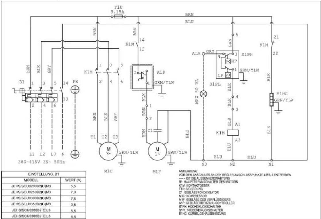
JEHSCU0400CM3, JEHSCU0500CM3, JEHSCU0600CM3, JEHSCU0680CM3, JEHSCU0400CL3, JEHSCU0500CL3, JEHSCU0600CL3
JEHSCU0800CM3, JEHSCU1000CM3
JEHSCU0750CL3
JEHSCU0950CL3 EVI
12. Anhang
CHECKLISTE VOR DEM START
natural_image
Diagram of two air conditioning units with fan blades, connected by lines (no text or symbols)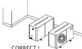
natural_image
Diagram of two air conditioning units connected by lines, with 'CORRECT!' text below (no other symbols or labels)natural_image
Technical line drawing of a mechanical air conditioning unit with fan and control panel (no text or symbols)
Série 2


natural_image
Technical line drawing of a multi-compartment air conditioning unit with fan and cooling unit (no text or symbols)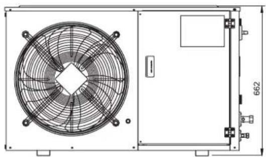
natural_image
Technical line drawing of a fan assembly with internal blades and mounting bracket (no text or symbols)Série 3
natural_image
Technical drawing of a dual fan installation with mounting holes and dimension label (no text or symbols)
natural_image
Technical line drawing of a multi-level industrial air conditioning unit with two fans (no text or symbols)Basse Température

natural_image
Technical drawing of a dual-panel air fan assembly with dimension annotations (no text or symbols on the fan itself)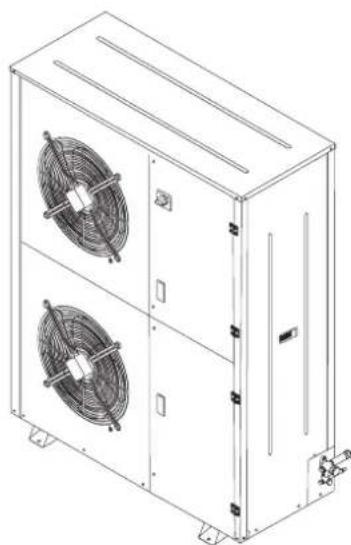
natural_image
Technical line drawing of a dual-chamber HVAC unit with two fans (no text or symbols)JEHSCU0200CM3, JEHSCU0250CM3, JEHSCU0300CM3, JEHSCU0350CM3, JEHSCU0200CL3, JEHSCU0300CL3
JEHSCU0400CM3, JEHSCU0500CM3, JEHSCU0600CM3, JEHSCU0680CM3, JEHSCU0400CL3, JEHSCU0500CL3, JEHSCU0600CL3
JEHSCU0800CM3, JEHSCU1000CM3
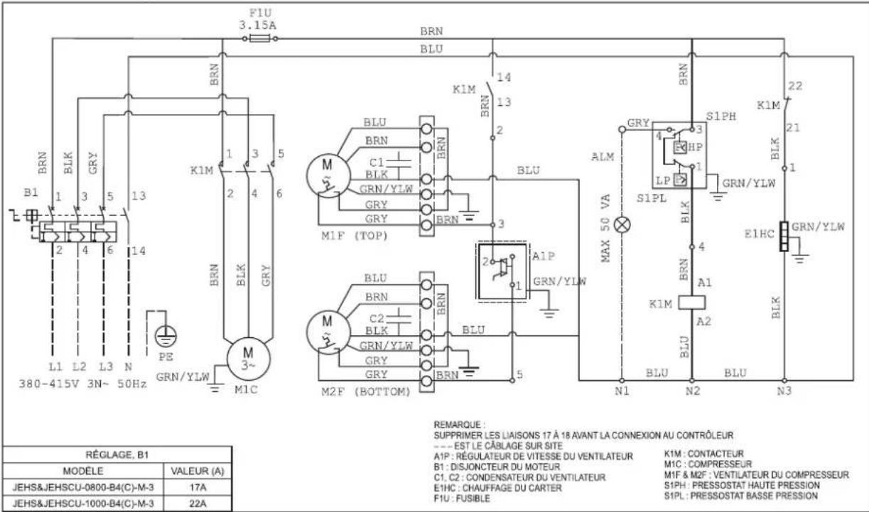
JEHSCU0750CL3
JEHSCU0950CL3 EVI

12. Annexe
LISTE DE VÉRIFICATION AVANT DÉMARRAGE
natural_image
Diagram of two air conditioning units with fan-like heat sinks, connected by a line (no text or symbols)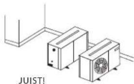
natural_image
Technical line drawing of two air conditioning units connected by lines, labeled 'JUIST!' (no other text or symbols)$$ = 3. 7 0 7 \mathrm{kW} $$
natural_image
Technical drawing of a dual fan assembly with mounting holes and dimension label (no text or symbols)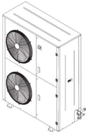
natural_image
Technical line drawing of a dual-panel air conditioning unit with two fans (no text or symbols)Lage Temperatuur


natural_image
Technical drawing of a dual-panel air fan assembly with dimension lines (no text or symbols)
natural_image
Technical line drawing of a multi-level industrial cooling unit with two fans (no text or symbols)Driefasig
JEHCCU0140CM3
JEHCCU0150CM3, JEHCCU0225CM3, JEHCCU0300CM3
JEHSCU0200CM3, JEHSCU0250CM3, JEHSCU0300CM3, JEHSCU0350CM3, JEHSCU0200CL3, JEHSCU0300CL3
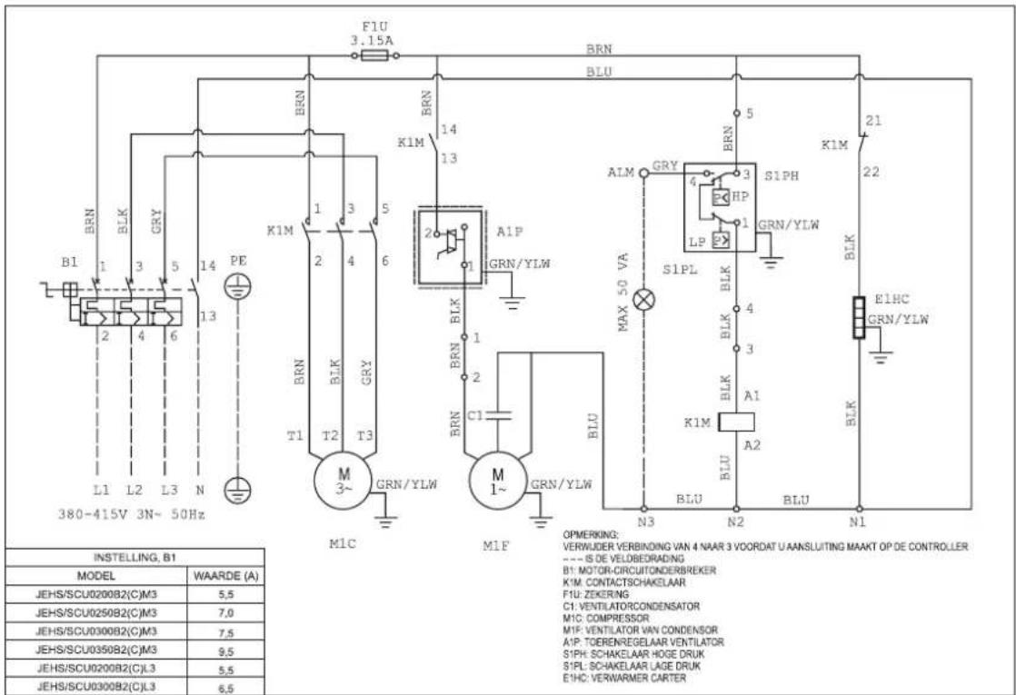
JEHSCU0400CM3, JEHSCU0500CM3, JEHSCU0600CM3, JEHSCU0680CM3, JEHSCU0400CL3, JEHSCU0500CL3, JEHSCU0600CL3
JEHSCU0800CM3, JEHSCU1000CM3
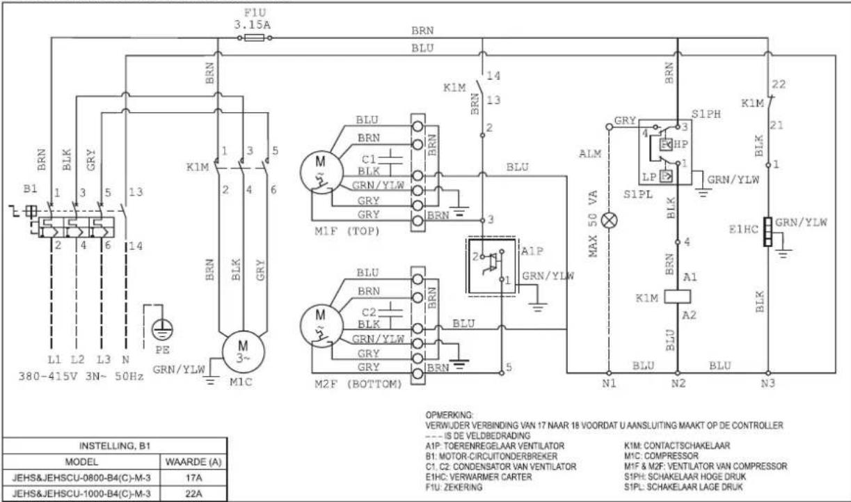
JEHSCU0750CL3
JEHSCU0950CL3 EVI
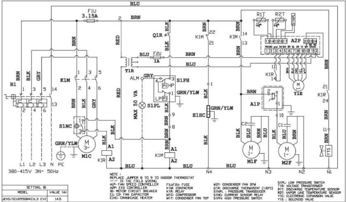
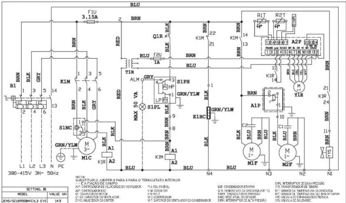
![BLU F1U 3.15A BRN Q1R BLK BRN 22 BRN 14 BRN R1T R2T S1NP 131 14 15 16 17 A2P 220 324 FRMMS and DIOX BL DR YE WTR 1 2 3 4 5 6 7 8 9 10 11 12 BRN BRN BRN BRN BRN BRN BRN BRN BRN BRN BRN BRN BRN BRN BRN BRN BRN BRN BRN BRN BRN BRN BRN BRN BRN BRN BRN BRN BRN BRN BRN BRN BRN BRN (L1 L2 L3 N PE) 380-415V 3N~ 50Hz B1 BRN BLK GRY K1M 1 3 5 6 7 8 9 10 11 12 ALM GRY ALM MAX 50 VA S1PL GRN/YLW E1HC GRN/YLW A1P A2 BLU BLU BLU BLU BLU BLU BLU BLU BLU BLU BLU BLU BLU BLU BLU BLU BLU BLU BLU BLU BLU BLU BLU BLU BLU BLU BLU BLU BLU BLU BLU BLU BLU BLU BLU BLU BLU BLU BLU BLU BLU BLU BLU BLU BLU BLU BLU BLU BLU BLU BL UMLAAR OPMERKING: VERWANG JUMPER & NAAR & VAN DE DINNENTHERMOSTAAT 35 DE BEDRADING VELD A1P PAN SPEED CONTROLLER FLI FZIF FUSE M2F CONDENSOR FAW BTW SIPL LAGE DRIUKSONKELAAR A2P EXO CONTROLLER KIN RELAIS Q1R GEEN KVUTING THERVOSTAAT [J30 C] B1 MOTOR CIRCUIT BREAKER KIR RELAY S1NP LDRUKOPNEBER TUR SPANNING TRANSFORDATOR C1 C2 FAN CONDENSATOR M1C COMPRESSOR S1NC HUIDGE SENSOR RELAY R2T GEEN KVUTING TEMPERATURSENSOR E1HC CARTER RACHEL MIF CONDENSOR FANTOR S1PH HOEGEDRUK SWITCH R2T DAM PLOW TEMPERATUREURSENSOR Y1C HUIDGE SENSOR RELAY Y1E ELECTRONISC EXPANSICKLES Y1S WAGNEETVENTIL. JOHS/SCU0950B4CCL3 EVI I4.5](/content/2026/04/691138/images/52d5daca56567da7520a1bb95a4c9820a5def90c4b7f17964a6c8c8e3a6f48b4.jpg)
12. Bijlage
CONTROLELIJST VOORAFGAAND AAN OPSTARTEN
natural_image
Technical line drawing of two air conditioning units with fan-like blades, connected by lines (no text or symbols)¡INCORRECTO!
natural_image
Diagram of two air conditioning units with a labeled correct model (no text or symbols on the devices themselves)¡CORRECTO!
$$ = 3. 7 0 7 \mathrm{kW} $$
natural_image
Technical line drawing of a mechanical air conditioning unit with fan and control panel (no text or symbols)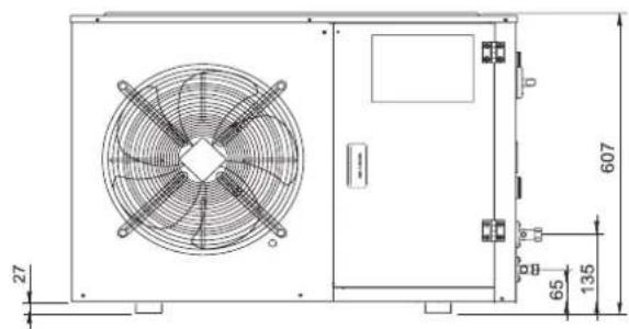
Serie 2

natural_image
Technical line drawing of a mechanical air conditioning unit with fan and cooling unit (no text or symbols)
natural_image
Technical line drawing of an air conditioning fan assembly with mounting bracket (no text or symbols)Serie 3
Serie 4
Temperatura Media

natural_image
Technical drawing of a dual fan assembly with mounting holes and dimension label (no text or symbols)
natural_image
Technical line drawing of a dual-panel air conditioning unit with two fans (no text or symbols)Temperatura Baja

natural_image
Technical drawing of a dual-panel air fan assembly with dimension lines (no text or symbols)
natural_image
Technical line drawing of a dual-chamber HVAC unit with two fans (no text or symbols)JEHSCU0200CM3, JEHSCU0250CM3, JEHSCU0300CM3, JEHSCU0350CM3, JEHSCU0200CL3, JEHSCU0300CL3
JEHSCU0400CM3, JEHSCU0500CM3, JEHSCU0600CM3, JEHSCU0680CM3, JEHSCU0400CL3, JEHSCU0500CL3, JEHSCU0600CL3
JEHSCU0800CM3, JEHSCU1000CM3
JEHSCU0750CL3
JEHSCU0950CL3 EVI

12. Apéndice
3.4 Tubature in loco
Nota importante
$$ = 3. 7 0 7 \mathrm{kW} $$
- PT5 : BR: MARRONE; WH: BIANCO
natural_image
Technical drawing of a dual fan assembly with mounting holes and dimension label (no text or symbols)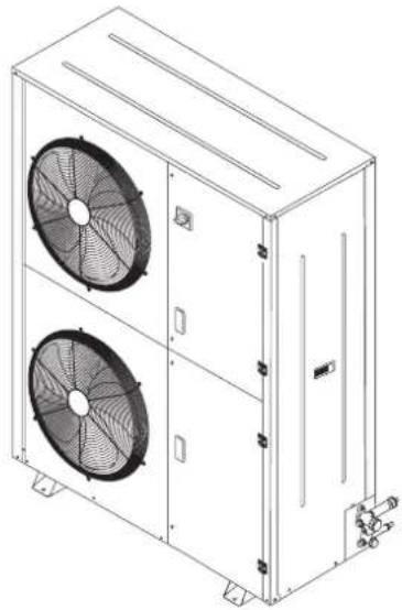
natural_image
Technical line drawing of a dual-panel air conditioning unit with two fans (no text or symbols)Temperatura Bassa

natural_image
Technical drawing of a dual-panel air fan assembly with dimension annotations (no text or symbols on the fan itself)
natural_image
Technical line drawing of a multi-level industrial cooling unit with two fans (no text or symbols)11. Dati elettrici
JEHCCU0150CM1, JEHCCU0225CM1, JEHCCU0300CM1
JEHSCU0200CM1, JEHSCU0250CM1, JEHSCU0300CM1
Trifase
JEHCCU0140CM3
JEHCCU0150CM3, JEHCCU0225CM3, JEHCCU0300CM3
JEHSCU0200CM3, JEHSCU0250CM3, JEHSCU0300CM3, JEHSCU0350CM3, JEHSCU0200CL3, JEHSCU0300CL3
JEHSCU0400CM3, JEHSCU0500CM3, JEHSCU0600CM3, JEHSCU0680CM3, JEHSCU0400CL3, JEHSCU0500CL3, JEHSCU0600CL3
JEHSCU0800CM3, JEHSCU1000CM3
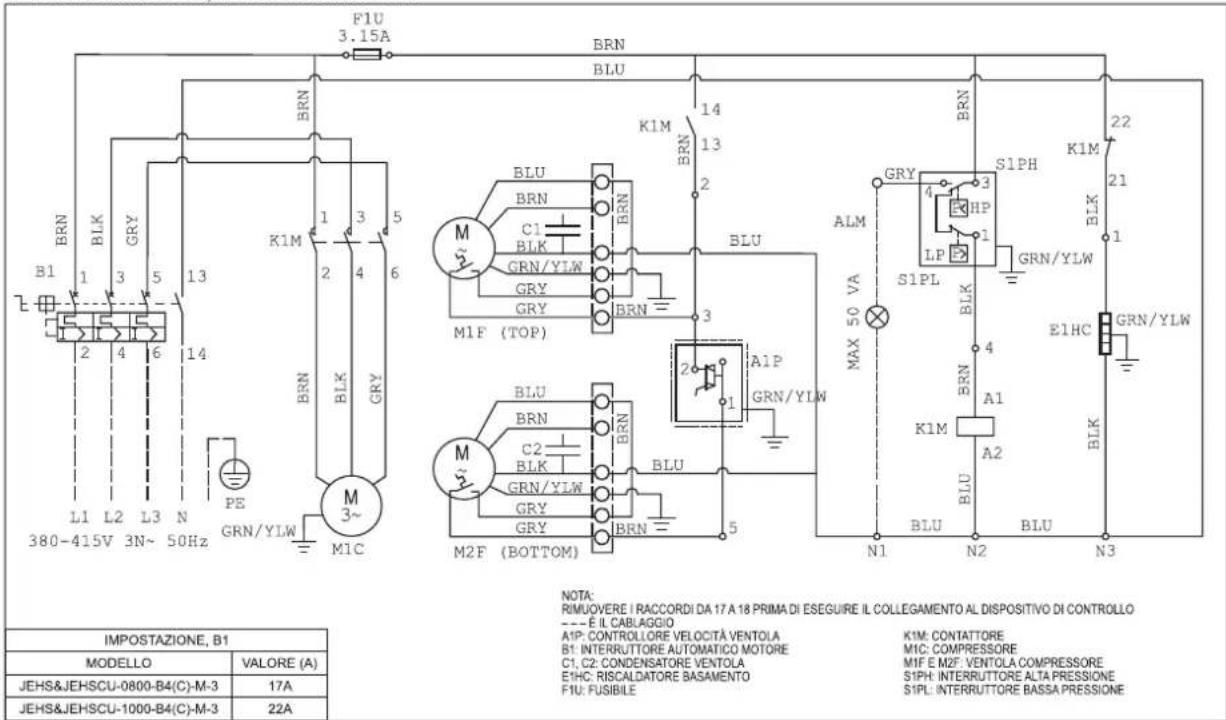
JEHSCU0750CL3
JEHSCU0950CL3 EVI
12. Appendice
$$ = 3. 7 0 7 \mathrm{kW} $$
natural_image
Technical line drawing of a mechanical air conditioning unit with fan and control panel (no text or symbols)
Série 2


natural_image
Technical line drawing of a mechanical air conditioning unit with fan and cooling unit (no text or symbols)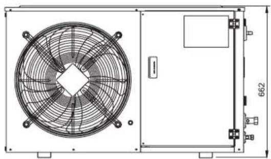
natural_image
Technical line drawing of an air conditioning fan assembly with mounting bracket (no text or symbols)Série 3

Série 4
Temperatura Média


natural_image
Technical drawing of a dual fan assembly with mounting holes and dimension label (no text or symbols)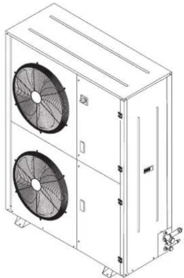
natural_image
Technical line drawing of a dual-panel air conditioning unit with two fans (no text or symbols)Temperatura Baixa


natural_image
Technical drawing of a dual-panel air fan assembly with dimension lines (no text or symbols)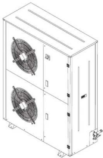
natural_image
Technical line drawing of a dual-panel industrial cooling unit with two fans (no text or symbols)11. Dados Elétricos
JEHCCU0051CM1; JEHCCU0063CM1; JEHCCU0077CM1
JEHCCU0067CM1; JEHCCU0095CM1; JEHCCU0100CM1; JEHCCU0113CM1, JEHCCU0115CL1
JEHCCU0140CM1
JEHCCU0150CM1, JEHCCU0225CM1, JEHCCU0300CM1
JEHSCU0200CM1, JEHSCU0250CM1, JEHSCU0300CM1
Trifásico
JEHCCU0140CM3
JEHCCU0150CM3, JEHCCU0225CM3, JEHCCU0300CM3
JEHSCU0200CM3, JEHSCU0250CM3, JEHSCU0300CM3, JEHSCU0350CM3, JEHSCU0200CL3, JEHSCU0300CL3

JEHSCU0400CM3, JEHSCU0500CM3, JEHSCU0600CM3, JEHSCU0680CM3, JEHSCU0400CL3, JEHSCU0500CL3, JEHSCU0600CL3
JEHSCU0800CM3, JEHSCU1000CM3
JEHSCU0750CL3
JEHSCU0950CL3 EVI
12. Apêndice
$$ = 3. 7 0 7 \mathrm{kW} $$
natural_image
Technical line drawing of a mechanical air conditioning unit with fan and control panel (no text or symbols)
Σειρά 2


natural_image
Technical line drawing of a multi-compartment air conditioning unit with fan and cooling unit (no text or symbols)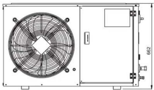
natural_image
Technical line drawing of an air conditioning fan assembly with mounting bracket (no text or symbols)Σειρά 3
natural_image
Technical drawing of a dual fan assembly with mounting holes and dimension label (no text or symbols)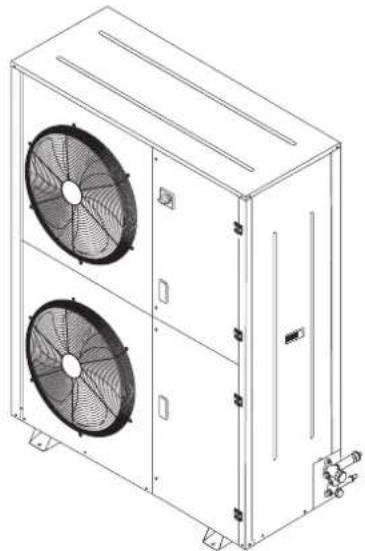
natural_image
Technical line drawing of a dual-panel air conditioning unit with fans and cooling fins (no text or symbols)Χαμηλή θερμοκρασία


natural_image
Technical drawing of a dual-panel air fan assembly with dimension annotations (no text or symbols on the fan bodies)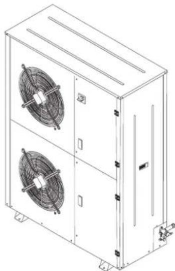
natural_image
Technical line drawing of a multi-level industrial cooling unit with two fans (no text or symbols)JEHCCU0150CM1, JEHCCU0225CM1, JEHCCU0300CM1
JEHSCU0200CM1, JEHSCU0250CM1, JEHSCU0300CM1
Τριφασικό
JEHCCU0140CM3
JEHSCU0200CM3, JEHSCU0250CM3, JEHSCU0300CM3, JEHSCU0350CM3, JEHSCU0200CL3, JEHSCU0300CL3

JEHSCU0400CM3, JEHSCU0500CM3, JEHSCU0600CM3, JEHSCU0680CM3, JEHSCU0400CL3, JEHSCU0500CL3, JEHSCU0600CL3
JEHSCU0800CM3, JEHSCU1000CM3
JEHSCU0750CL3
JEHSCU0950CL3 EVI
12. Παράρτημα
$$ = 3. 7 0 7 \mathrm{kW} $$
All specifications are subjected to change by the manufacturer without prior notice. The English text is the original instruction. Other languages are the translations of the original instructions.
POLSKI
natural_image
Technical line drawing of a mechanical air conditioning unit with fan and control panel (no text or symbols)
Seria 2
natural_image
Technical line drawing of a mechanical air conditioning unit with fan and cooling unit (no text or symbols)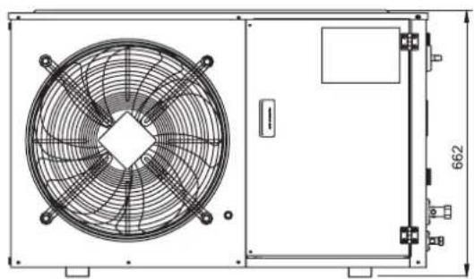
natural_image
Technical line drawing of an air conditioning fan assembly with mounting bracket (no text or symbols)Seria 3

natural_image
Technical drawing of a dual fan installation with mounting holes and dimension label (no text or symbols beyond measurement markers)
natural_image
Technical line drawing of a multi-level industrial air conditioning unit with two fans (no text or symbols)Niskotemperaturowe


natural_image
Technical drawing of a dual-panel HVAC fan assembly with dimension annotations (no text or symbols on the fan bodies)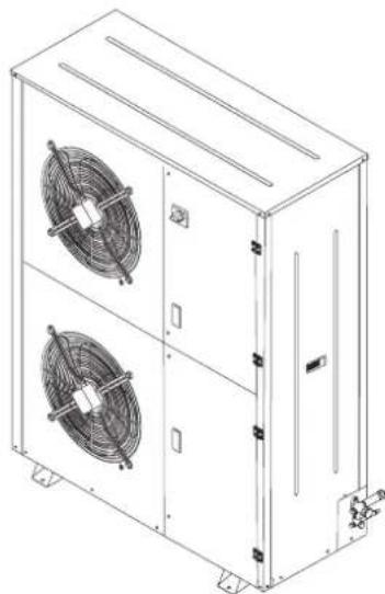
natural_image
Technical line drawing of a multi-level industrial air conditioning unit with two fans (no text or symbols)Trójfazowy
JEHCCU0140CM3
JEHCCU0150CM3, JEHCCU0225CM3, JEHCCU0300CM3
JEHSCU0200CM3, JEHSCU0250CM3, JEHSCU0300CM3, JEHSCU0350CM3, JEHSCU0200CL3, JEHSCU0300CL3
JEHSCU0400CM3, JEHSCU0500CM3, JEHSCU0600CM3, JEHSCU0680CM3, JEHSCU0400CL3, JEHSCU0500CL3, JEHSCU0600CL3
JEHSCU0800CM3, JEHSCU1000CM3
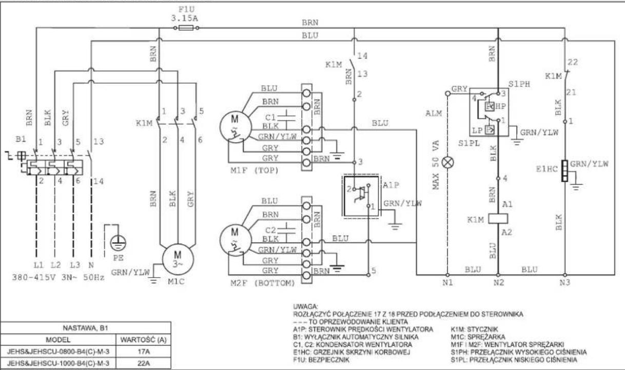
JEHSCU0750CL3
JEHSCU0950CL3 EVI
12. Załącznik
LISTA KONTROLNA CZYNNOŚCI DO WYKONANIA PRZED ROZRUCHEM
- Installation Manual
- Operation Manual
- Contents
- Nomenclature
- Safety and Health
- General Information
- Important Note
- Installation & Commissioning
- Unit site location
- Installation Clearance
- Compressor handling
- Field Piping
- Pressure testing
- Leak detection
- Vacuum - moisture removal
- Safety pressure switch settings
- High pressure safety (Manual reset)
- Low pressure safety (Auto reset)
- Fan speed controller setting
- Commissioning of the Condensing Unit
- Compressor electrical wiring
- Earthing of Condensing Unit
- Series 4 EVI Unit
- Piping Size Selection
- Insulation Selection
- Expansion Valve Selection
- Controller EXD-HP1
- Safety Instructions:
- Electrical Installation
- Display / keypad unit (LEDs and button functions)
- Digital Input Di1/Di2
- Manual mode operation
- Manual alarm reset clearing functional alarms (except hardware error)
- Decommissioning & Disposal
- Checklist
- Service and Maintaintenance
- F-Gas Information
- Important information regarding the refrigerant used
- Trouble Shooting
- Specifications
- O-CU06-AUG17-3
- Outline drawings
- Series 4
- Electrical Data
- Single Phase
- Three Phase
- Appendix
- Additional advice:
- Installationshandbuch
- Bedienungsanleitung
- Elektro-Daten
- Anhang
- Annexe
- Driefasig
- Bijlage
- Apéndice
- Tubature in loco
- Nota importante
- Dati elettrici
- Trifase
- Appendice
- Dados Elétricos
- Trifásico
- Apêndice
- Τριφασικό
- Παράρτημα
- Trójfazowy
- Załącznik
Brand : DAIKIN
Model : JEHSCU0750CL3
Category : Fridge