
CIRKULERA 905.152.93 - Cooker IKEA - Free user manual and instructions
Find the device manual for free CIRKULERA 905.152.93 IKEA in PDF.

| Product Type | Gas Range |
| Brand | IKEA |
| Model | CIRKULERA 905.152.93 |
| Height | 91.1 - 93.7 cm |
| Width | 60 cm |
| Depth | Approximately 60 cm (without handle) |
| Weight | Approximately 55 kg |
| Gas Supply | Natural gas (convertible to LPG with kit) |
| Electrical Supply | 120 V ~ 60 Hz, 15 A, dedicated circuit |
| Surface Burner Type | 4 sealed burners (round and oval) |
| Oven | Gas oven with electric ignition |
| Broiler | Broiler burner (model varies by version) |
| Functions | Baking, roasting, broiling, warming |
| Anti-tip device | Wall or floor mounting bracket included |
| Safety | Electric ignition, oven safety shutoff |
| Care and Cleaning | Clean after each use; remove burner caps; do not steam clean |
| Replacement Parts | LPG conversion kit, brackets, grates (available at IKEA) |
| Repairability | Installation and service by qualified professional |
| General Information | Complies with CSA, ANSI Z223.1, NEC standards |
Frequently Asked Questions - CIRKULERA 905.152.93 IKEA
User questions about CIRKULERA 905.152.93 IKEA
0 question about this device. Answer the ones you know or ask your own.
Ask a new question about this device
Download the instructions for your Cooker in PDF format for free! Find your manual CIRKULERA 905.152.93 - IKEA and take your electronic device back in hand. On this page are published all the documents necessary for the use of your device. CIRKULERA 905.152.93 by IKEA.
USER MANUAL CIRKULERA 905.152.93 IKEA
natural_image
Line drawing of a simple kitchen oven with multiple fans and control knobs (no text or symbols)
INSTALLATION AND SERVICE MUST BE PERFORMED
BY A QUALIFIED INSTALLER.
IMPORTANT: SAVE FOR LOCAL ELECTRICAL INSPECTOR'S USE.
READ AND SAVE THESE INSTRUCTIONS FOR FUTURE REFERENCE.

WARNING!
FOR YOUR SAFETY: Do not store or use gasoline or other flammable vapors and liquids in the vicinity of this or any other appliance.
Your safety and the safety of others are very important.
We have provided many important safety messages in this manual and on your appliance. Always read and obey all safety messages.

This is the safety alert symbol.
This symbol alerts you to potential hazards that can kill or hurt you and others.
All safety messages will follow the safety alert symbol and either the word "WARNING" or "CAUTION."

WARNING!
Indicates a potentially hazardous situation which, if not avoided, may result in death or serious injury.

CAUTION!
Indicates a potentially hazardous situation which, if not avoided, may result in minor or moderate injury.
All safety messages will tell you what the potential hazard is, tell you how to reduce the chance of injury, and tell you what can happen if the instructions are not followed.

WARNING!
If the information in this manual is not followed exactly, a fire or explosion may result causing property damage, personal injury or death.
FOR YOUR SAFETY:
— Do not store or use gasoline or other flammable vapors and liquids in the vicinity of this or any other appliance.
— WHAT TO DO IF YOU SMELL GAS:
- Do not try to light any appliance.
- Do not touch any electrical switch; do not use any phone in your building.
- Immediately call your gas supplier from a neighbor's phone.
- Follow the gas supplier's instructions.
- If you cannot reach your gas supplier, call the fire department.
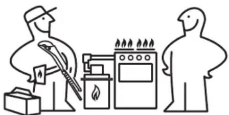
- Installation and service must be performed by a qualified installer, service agency or the gas supplier.

WARNING!

Tip Over Hazard
- A child or adult can tip the range and be killed.
-
Verify the anti-tip device has been installed to floor or wall.
-
Ensure the anti-tip device is re-engaged when the range is moved to floor or wall.
- Do not operate the range without the anti-tip device in place and engaged.
- Failure to follow these instructions can result in death or serious burns to children and adults.
Range
leveling leg
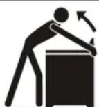
To check if the anti-tip bracket is installed properly, use both arms and grasp the rear edge of range back. Carefully attempt to tilt range forward. When properly installed, the range should not tilt forward.
Refer to the anti-tip bracket installation instructions supplied with your range for proper installation.
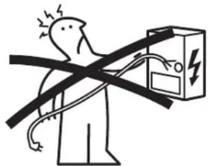
Electric Shock Hazard
Disconnect power before servicing.
Use 12-gauge solid copper wire.
Electrically ground oven.
Failure to follow these instructions can result in death, fire, or electrical shock.
Provide proper fuel type
Before proceeding: Your range is factory preset to operate on natural gas. If L.P. conversion is needed, contact your local L.P. Gas provider for assistance.
The L.P. conversion kit may be located on the lower rear back panel of the range. If no L.P. kit is provided, contact your product dealer to obtain the correct L.P. conversion kit.
Important notes to the installer
- Read all instructions contained in these installation instructions before installing range.
- Remove all packing material from the oven compartments before connecting the gas and electrical supply to the range.
- Observe all governing codes and ordinances.
- Be sure to leave these instructions with the consumer.
- All materials used in construction of cabinets, enclosures, and supports surrounding the product must have a temperature rating above 194°F (90°C).
Important notes to the consumer
- Keep these instructions with your User manual for future reference.
- Be sure your range is installed and grounded properly by a qualified installer or service technician.
Special instructions for appliances installed in the State of Massachusetts:
This appliance can only be installed in the State of Massachusetts by a Massachusetts licensed plumber or gas fitter. When using a flexible gas connector, it must not exceed 3 feet (36 inches) in length. A "T" handle type manual gas valve must be installed in the gas supply line to this appliance.
IMPORTANT SAFETY INSTRUCTIONS
- Installation of this range must conform with local codes or, in the absence of local codes, with the National Fuel Gas Code ANSI Z223.1—latest edition when installed in the United States.
- When installed in a manufactured (mobile) home, installation must conform with the Manufactured Home Construction and Safety Standard, Title 24 CFR, Part 3280 [formerly the Federal Standard for Mobile Home Construction and Safety, Title 24, HUD (Part 280)] or, when such standard is not applicable, the Standard for Manufactured Home Installations, ANSI/NCSBCS A225.1, or with local codes.
- This range has been design certified by CSA International. As with any appliance using gas and generating heat, there are certain safety precautions you should follow. You will find them in the User manual, read it carefully.
- Be sure your range is installed and grounded properly by a qualified installer or service technician.
- This range must be electrically grounded in accordance with local codes or, in their absence, with the National Electrical Code ANSI/NFPA No .70—latest edition when installed in the United States. See Grounding Instructions on page 11.
- Before installing the range in an area covered with linoleum or any other synthetic floor covering, make sure the floor covering can withstand heat at least 90°F above room temperature without shrinking, warping or discoloring. Do not install the range over carpeting unless you place an insulating pad or sheet of 1/4-inch thick plywood between the range and carpeting.
- Make sure the wall coverings around the range can withstand the heat generated by the range.
- Do not obstruct the flow of combustion air at the oven vent nor around the base or beneath the lower front panel of the range. Avoid touching the vent openings or nearby surfaces as they may become hot while the oven is in operation. This range requires fresh air for proper burner combustion.
- Air curtain or other overhead range hoods, which operate by blowing a downward air flow on to a range, shall not be used in conjunction with gas ranges other than when the hood and range have been designed, tested and listed by an independent test laboratory for use in combination with each other.

WARNING!
DO NOT MAKE ANY ATTEMPT TO OPERATE THE ELECTRIC IGNITION OVEN DURING AN ELECTRICAL POWER FAILURE. RESET ALL OVEN CONTROLS TO "OFF" IN THE EVENT OF A POWER FAILURE.
The electric ignitor will automatically re-ignite the oven burner when power resumes if the oven thermostat control was left in the "ON" position.
When an electrical power failure occurs during use, the surface burners will continue to operate.
During a power outage, the surface burners can be lit with a match. Hold a lighted match to the burner, then slowly turn the knob to the LITE position. Use extreme caution when lighting burners this way.

WARNING!
The electrical power to the cooktop must be shut off while gas line connections are being made. Failure to do so could result in serious injury or death.

WARNING!
Never leave children alone or unattended in the area where an appliance is in use. Teach children the proper, safe use of all appliances. Never leave the oven door open when the range is unattended.
Stepping, leaning or sitting on the doors or drawers of this range can result in serious injuries and can also cause damage to the range.
- Do not store items of interest to children in the cabinets above the range. Children could be seriously burned climbing on the range to reach items.
- To eliminate the need to reach over the surface burners, cabinet storage space above the burners should be avoided.
- Adjust surface burner flame size so it does not extend beyond the edge of the cooking utensil. Excessive flame is hazardous.
- Do not use the oven as a storage space. This creates a potentially hazardous situation.
- Never use your range for warming or heating the room. Prolonged use of the range without adequate ventilation can be dangerous.
- Do not store or use gasoline or other flammable vapors and liquids near this or any other appliance. Explosions or fires could result.
- Reset all controls to the "OFF" position after using a programmable timing operation.
- Unlike some gas ranges, the cooktop is not removable. Do not attempt to remove the cooktop.
natural_image
Simple line drawing of a person with a lightning bolt symbol crossed out by a box (no text or labels)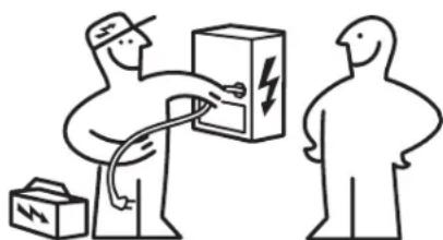
natural_image
Illustration of two delivery workers handling a box with a lightning bolt symbol (no text or labels)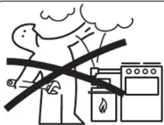
natural_image
Simple line drawing of two figures in a kitchen setting with tools and equipment (no text or symbols)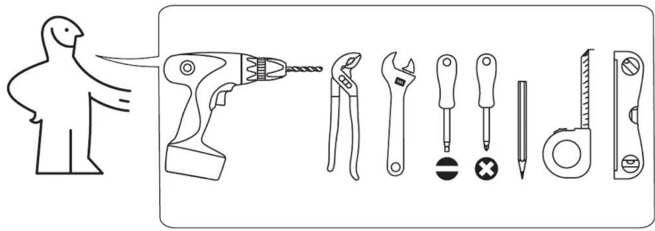

natural_image
Two stylized human figures standing on wooden blocks, one crossed with a hammer and the other holding a hammer, both without any text or symbols.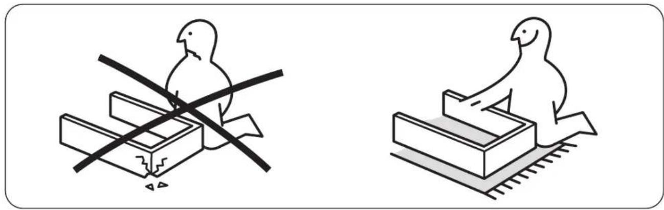
natural_image
Two line drawings of birds on different platforms, one with a crosshair and the other with a smiley face (no text or symbols)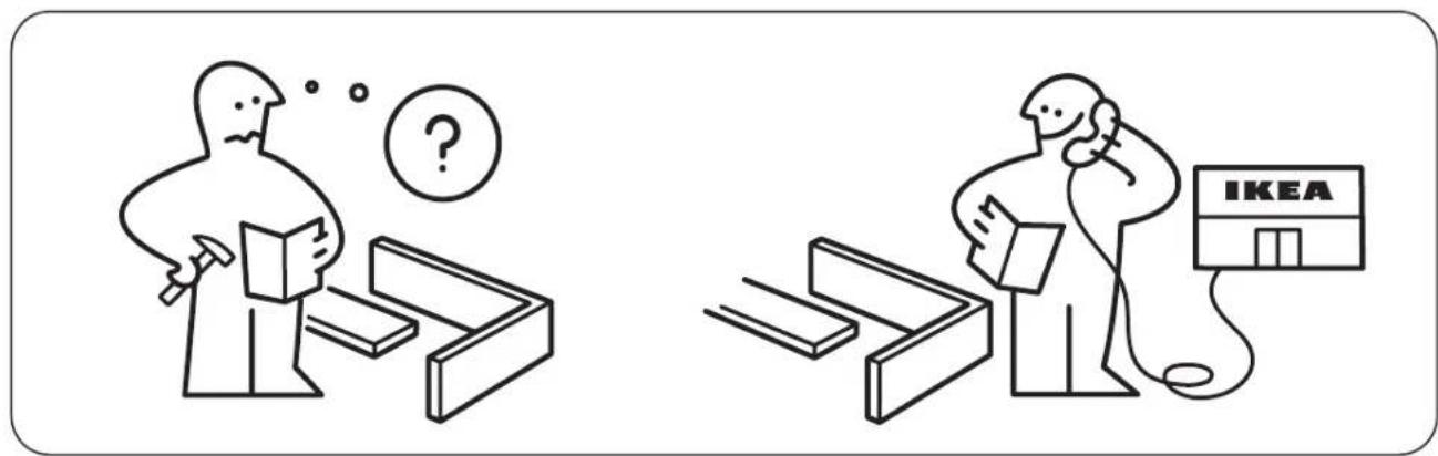
Tools you will need
(Wear safety glasses when using tools):
For leveling legs and Anti-Tip Bracket:
- Adjustable wrench or channel lock pliers
- 5/16" Nutdriver or flat head screwdriver
- Electric drill & 1/8" drill bit (3/16" Masonry drill bit if installing in concrete)
- Spirit Level
- Tape measure
For gas supply connection:
- Adjustable wrench and pipe wrench
For burner flame adjustment:
• Phillips head and small flat-blade screwdrivers
Materials you will need:
- Pipe joint sealant that resists action of LP/Propane gas (Fig. a)
• Gas line manual shut-off valve (Fig. b) - Use new flare union adapters (1/2" NPT x 3/4" or 1/2" I.D.) (Fig. c)
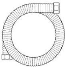
- A new flexible metal appliance conduit (1/2" NPT x 3/4" or 1/2" I.D.) must be design certified by CSA International. Because solid pipe restricts moving the range, we recommend using a new flexible conduit (4 to 5 foot length) for each new installation and additional reinstallations. (Fig. d)
Materials
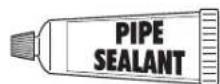
Fig. a
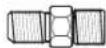
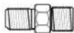
Fig. c

Fig.b
natural_image
Simple line drawing of a circular mechanical component with flanged ends and a small rectangular end (no text or symbols)Fig. d
Materials supplied with appliance
1x 1x
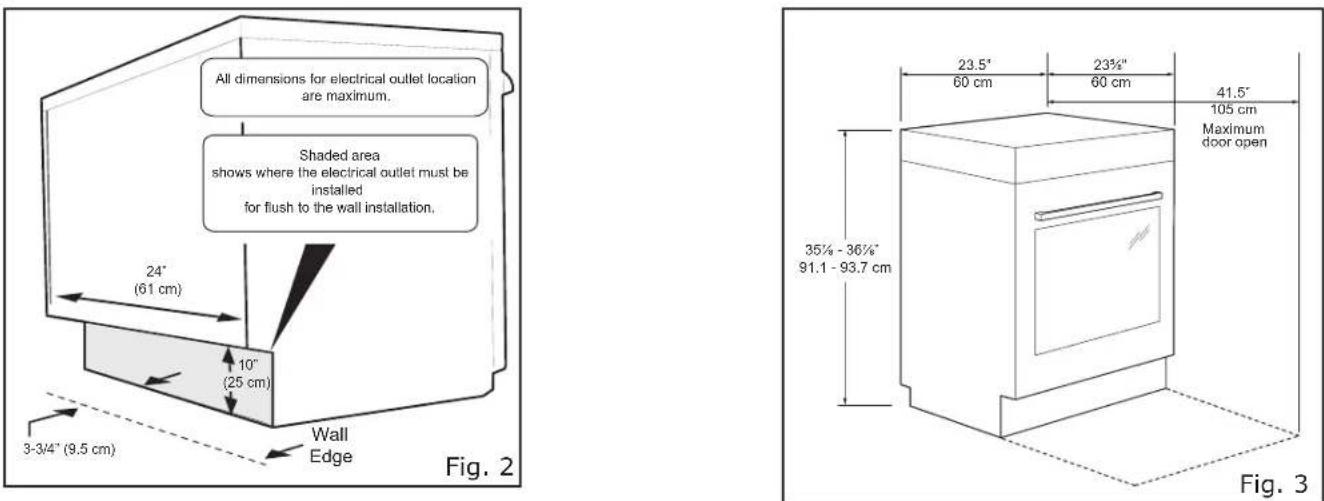
Clearances and Dimensions
- Provide adequate clearances between the range and adjacent combustible surfaces.
- Location—Check location where the range will be installed. Check for proper electrical supply, and the stability of the floor.
- Dimensions that are shown must be used. Given dimensions provide minimum clearance. Contact surface must be solid and level.
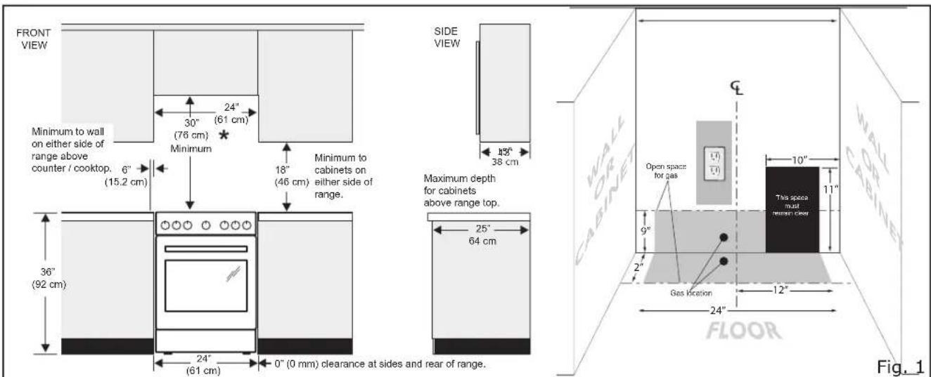
*30" Minimum clearance between the top of the cooking surface and the bottom of an unprotected wood or metal cabinet
24" minimum when bottom of wood or metal cabinet is protect by not less than 1/4" flame retardant mill-board covered with not less than No. 28 MSG sheet steel, 0.015" stainless steel, or 0.024" aluminum or 0.020" copper.
0" clearance is the minimum for the rear of the range. Follow all dimension requirements provided above to prevent property damage, potential fire hazard, and incorrect countertop and cabinet cuts.
To eliminate the risk of burns or fire be reaching over heated surface units, cabinet storage space located above the surface units should be avoided. If cabinet storage is to be provided, the risk can be reduced by installing a range hood that projects horizontally a minimum of 5" beyond the bottom of the cabinets.
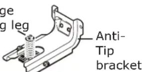
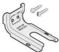
1. Install anti-tip bracket IMPORTANT SAFETY WARNING!
To reduce the risk of tipping of the range, the range must be secured to the floor by properly installed anti-tip bracket and screws packed with the range. Failure to install the anti-tip bracket will allow the range to tip over if excessive weight is placed on an open door or if a child climbs upon it. Serious injury might result from spilled hot liquids or from the range itself.
If range is ever moved to a different location, the anti-tip bracket must also be moved and installed with the range.
Instructions are provided for installation in wood or cement fastened to either the floor or wall. When installed to the wall, make sure that screws completely penetrate dry wall and are secured in wood or metal. When fastening to the floor or wall, be sure that screws do not penetrate electrical wiring or plumbing.
Anti-tip bracket installation instructions
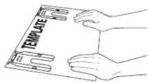
a. Locate the bracket using the template -
(Bracket may be positioned on either the left or right side of the range. Refer to Figs. 4, 5, & 7 to position the bracket if template is not available).
Mark the floor or wall where left or right side of the range will be located. If rear of range is against wall or no further than 1-1/4" from wall when installed, you may use the wall or floor mount method. If molding is installed and does not allow the bracket to fit flush against wall, remove molding or mount bracket to floor.
For wall mount (Fig. 4), locate the bracket by placing the back edge of the template against rear wall and the side edge of template on the mark made referencing the side of the range. Place bracket on top of template and mark location of the screw holes in wall. If rear of range is further than 1-1/4" from wall when installed, attach bracket to the floor (See Fig. 5).
FASTEN BRACKET (WALL OR FLOOR MOUNTING)
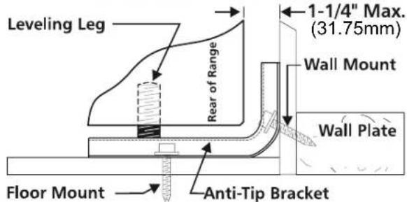
Fig. 4
FASTEN BRACKET (FLOOR MOUNTING ONLY)
Fig. 5
For floor mount, locate the bracket by placing back edge of the template where the rear of the range will be located. Mark the location of the screw holes shown in template.
b. Drill pilot holes & fasten bracket - Drill 1/8" pilot hole where screws are to be located
(Fig. 6). If bracket is to be mounted to the wall, drill pilot hole at an approximate 20° downward angle. If bracket is to be mounted to masonry or ceramic floors, drill 3/16" pilot hole 1-3/4" deep. The screws provided may be used in wood or concrete material. Use 5/16"
natural_image
Line drawing of a hand using a power drill on a workbench (no text or symbols)Fig. 6
nut-driver or flat head screwdriver to secure the bracket in place.
c. Level & position range - Level range by adjusting the (4) leveling legs with a wrench.
Note: A min. clearance of 1/8" is required between bottom of range and leveling legs to allow room for bracket.
Slide range back into position (Fig. 7). Remove lower panel or storage drawer to visually check that rear leveling leg is inserted into and fully secured by the bracket. For models with a warmer drawer or broiler compartment, grasp the top rear edge of the range and carefully attempt to tilt it forward.
Fig. 7
AA-2282382-1
2. Provide an adequate gas supply.
Please note: Operation at elevations above 2000 ft., appliance rating shall be reduced at the rate of 4 percent for each 1000 ft. above sea level.
This appliance is pre-set to operate on 4" natural gas manifold pressure. A convertible pressure regulator is connected to the manifold and MUST be connected in series with the gas supply line. If the LP/Propane conversion kit has been used, follow instructions provided with the kit for converting the pressure regulator to LP/Propane use.
Care must be taken during installation of range not to obstruct the flow of combustion and ventilation air.
For proper operation, the maximum inlet pressure to the regulator should be no more than 14 inches of water column pressure. The inlet pressure to the regulator must be at least 1 inch greater than regulator manifold pressure.
Example: If regulator is set for natural gas 4 inch manifold pressure, inlet pressure must be at least 5 inches; if regulator has been converted for LP/Propane gas 10 inch manifold pressure, inlet pressure must be at least 11 inches.
Leak testing of the appliance shall be conducted according to the instructions in step 4g.
The gas supply line should be 1/2" or 3/4" I.D.
3. Seal wall openings.
Seal any openings in the wall behind the range and in the floor under the range after gas supply line is installed.
4. Connect range to gas supply.
Note: To prevent leaks use pipe joint sealant on all male (outside) pipe threads. Do not allow gas pressure regulator to turn on pipe when tightening fittings.
a. Install an external manual gas shut-off valve to gas supply line in an accessible location outside of range. Be sure you know where and how to shut off the gas supply to the range (See Fig. 8).
b. Install 1/2" flare union adapter to gas pressure regulator using no more than 15ft./lbs. of torque (Refer to Fig. 8).
Fig. 8 - gas supply connections
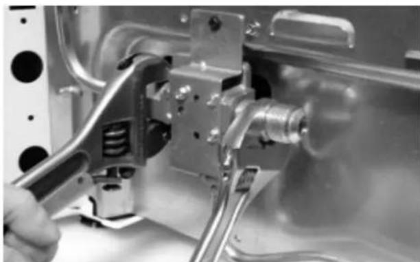
Be sure to stabilize the left side of the gas pressure regulator before tightening ANY fittings to the pressure regulator. Do not allow pressure regulator to turn on pipe when tightening fittings (Refer to Fig. 9).
natural_image
Close-up of a hand using a tool to adjust or install a mechanical component, no visible text or symbols.Fig. 9
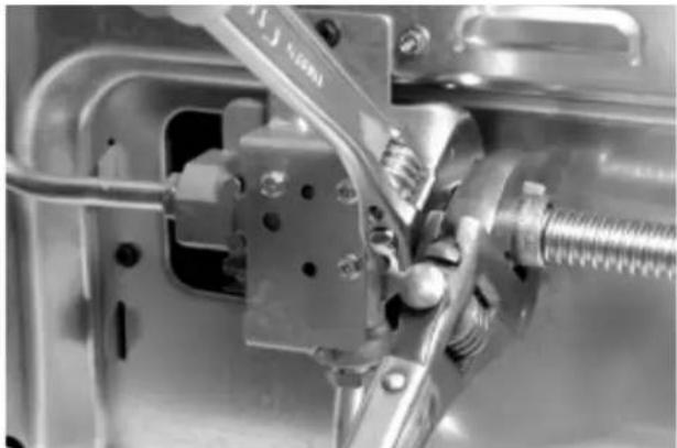
c. Tighten the gas supply fitting and/or appliance conduit to flare union adaptor on the right side of the pressure regulator (refer to Fig. 10) using NO MORE THAN 15ft./lbs. of torque. Be sure to stabilize the 1/2" flare union adapter with an adjustable wrench before tightening the gas supply fitting and/or appliance conduit.
natural_image
Close-up of a mechanical assembly with metal components and bolts (no visible text or symbols)Fig. 10
d. Install flare union adapter to external manual shut-off valve (See Fig. 8).
e. Attach flexible appliance conduit to flare union adaptor on shut-off valve (See Fig. 8).
f. Make sure the service shut-off valve on pressure regulator is set to the ON position (See Fig. 11).
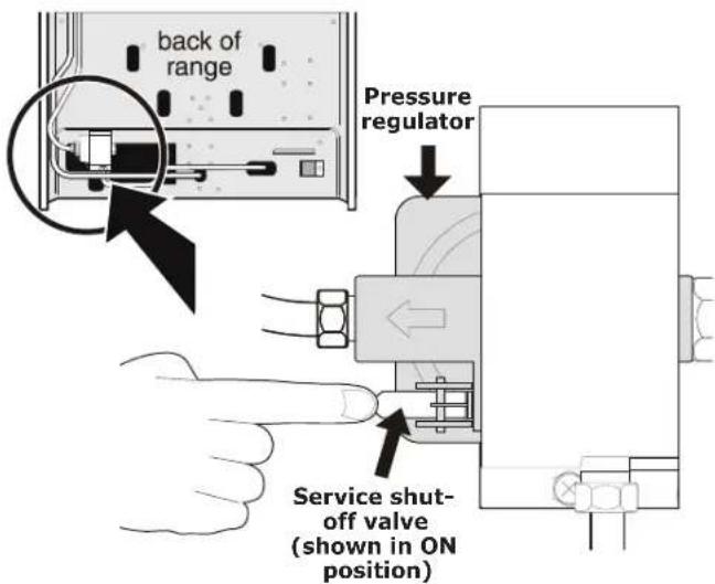
Fig. 11
g. Check for gas leaks. Turn the gas supply on to the range and use a liquid leak detector at all joints and conduits to check for leaks in the system.
Checking manifold gas pressure
WARNING!
Do not use flame to check for gas leaks.
Disconnect the range and its individual shut-off valve from the gas supply piping system during any pressure testing of that system at test pressures greater than 14" of water column pressure (approximately 1/2" psig).
The appliance must be isolated from the gas supply piping system by closing its individual manual shut-off valve during any pressure testing of the gas supply piping system at test pressures equal to or less than 14" of water column pressure (approximately 1/2" psig).
If it should be necessary to check the manifold gas pressure, connect manometer (water gauge) or other pressure device to the top burner right rear orifice. Using a rubber hose with inside diameter of approximately 1/4," hold tubing down tight over orifice. Turn burner valve on.
For an accurate pressure check have at least two (2) other top burners burning. Be sure the gas supply (inlet) pressure is at least one inch above specified range manifold pressure. The gas supply pressure should never be over 14" water column. When properly adjusted for Natural Gas the manifold pressure is 4". For LP/Propane Gas the manifold pressure is 10".
5. Read the following electrical connection details before connecting electricity to range.

WARNING!
Before servicing, disconnect electrical supply at circuit breaker, fuse or power cord.
Electric requirements:
A dedicated, properly grounded and polarized branch circuit protected by a 15 amp. circuit breaker or time delay fuse. See rating plate for proper voltage.
Extension cord precautions:
Because of potential safety hazards under certain conditions, we strongly recommend against the use of any extension cord. However, if you still choose to use an extension cord, it is absolutely necessary that it be a UL listed 3-wire grounding type appliance extension cord and that the current carrying rating of the cord in amperes be equivalent to or greater than the branch circuit rating. Such extension cords are obtainable through your local service organization.

WARNING!
Please read carefully! For personal safety, this product must be properly grounded.
Do not, under any circumstances, cut or remove the third (ground) prong from the power cord (See Fig. 12).
Where a standard two-prong wall receptacle is encountered, it is the personal responsibility and obligation of the customer to have it replaced with a properly grounded three-prong wall receptacle.
Preferred method
Grounding type wall receptacle
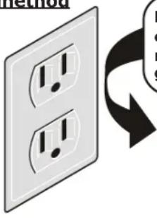
Do not, under any circumstances, cut, remove or bypass the grounding prong.
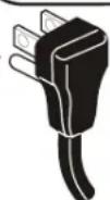
Power supply cord with 3-prong grounding plug
Fig. 12
Grounding instructions:
The power cord of this appliance is equipped with a 3-prong (grounding) plug which mates with a standard 3-prong grounding wall receptacle to minimize the possibility of electric shock hazard from this appliance. The customer should have the wall receptacle and circuit checked by a qualified electrician to make sure the receptacle is properly grounded and polarized.
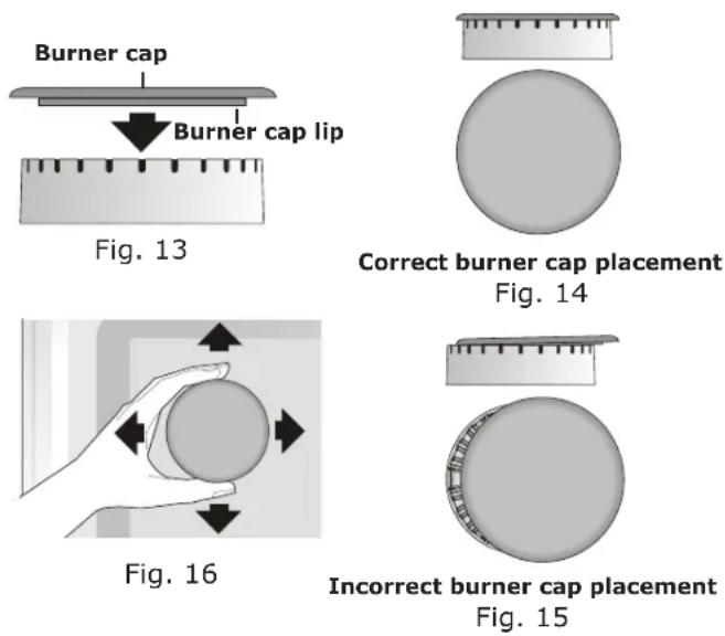
6. Check burner cap placement.
It is very important to be sure that all surface burner caps and burner grates are properly installed and in the correct locations before operating the appliance. Please note that the burner heads are secured to the cooktop. The cooktop is not removeable. Do not attempt to remove or lift the cooktop.

WARNING!
To prevent flare-ups and avoid creation of harmful by-products, do not use the cooktop without all burner caps properly installed to insure proper ignition and gas flame size.
Always keep the burner caps and burner heads in place whenever the surface burners are in use. Do not allow spills, food, cleaning agents or any other material to enter the gas orifice holder openings.
Check and be sure the size of each burner cap matches the size of the burner head. Check and be sure that all round style burner caps are correctly in place on round burner heads.
Check and be sure that all oval style burner caps are correctly in place on oval burner heads (if equipped). Check and be sure that all dual or twin style burner caps are correctly in place on dual or twin burner heads (if equipped).
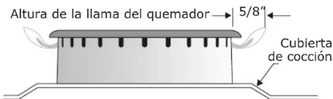
On round style burners, the burner cap lip (See Fig. 13) should fit snug into the center of burner head and be level. Refer to Figs. 14 & 15 for correct and incorrect burner cap placement.
Once in place, you may check the fit by gently sliding the burner cap from side to side (Fig. 16) to be sure it is centered and firmly seated. When the burner cap lip makes contact inside the center of the burner head you will be able to hear the burner cap click. Please note that the burner cap should NOT move off the center of the burner head when sliding from side to side.
7. Check ignition of surface burners.
Operation of electric igniters should be checked after range and supply line connectors have been carefully checked for leaks and range has been connected to electric power.
a. To check for proper ignition, push in and turn a surface burner knob counterclockwise to the LITE position. You will hear the igniter sparking.
b. The surface burner should ignite when gas is available to the burner. Purge air from supply lines by leaving knob in the LITE position until burner ignites. Each burner should light within four (4) seconds in normal operation after air has been purged from supply lines.
c. Visually check that burner has a flame. Once the burner ignites, the control knob should be turned out of the LITE position.
d. Try each surface control knob separately until all surface burners have been checked. Each burner location is equipped with a separate electrode.
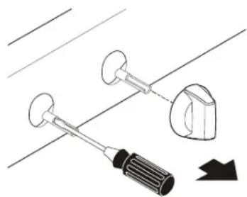
8. Adjust LOW setting of surface burner valves (linear flow).
Test to verify if LOW setting should be adjusted:
a. Push in and turn control to LITE until burner ignites.
b. Push in and quickly turn knob to lowest position.
c. If burner goes out, reset control to OFF.
d. Remove the surface burner control knob.
e. Insert a thin-bladed screwdriver into the hollow valve stem and engage the slotted screw inside. Flame size can be increased or decreased with the turn of the screw (see Fig. 17 and Fig. 18).
f. Adjust flame until you can quickly turn knob from LITE to lowest position without extinguishing the flame. Flame should be as small as possible without extinguishing.
Note: Air mixture adjustments are not required on surface burners.
natural_image
Technical illustration of a tool and bracket assembly with no visible text or symbolsFig. 17
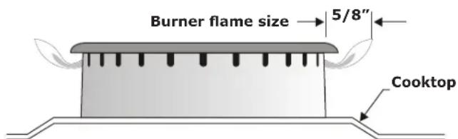
Fig. 18
9. Check ignition of oven burners.
The operation of oven igniters should be checked after range and supply line connectors have been carefully checked for leaks and range has been connected to electric power. Be sure all packing materials and literature are removed from oven.
The oven burner is equipped with an electric control system as well as an electric oven burner igniter. If your model is equipped with an upper oven burner, it will also have an electric burner igniter. These control systems require no adjustment. When the oven is set to operate, current will flow to the igniter. It will "glow" similar to a light bulb. When the igniter has reached a temperature sufficient to ignite gas, the electrically controlled oven valve will open and flame will appear at the oven burner. There is a time lapse from 30 to 60 seconds after the thermostat is turned ON before the flame appears at the oven burner. When the oven reaches the set temperature, the glowing igniter will cycle off. The burner flame will turn off in 20 to 30 seconds after the igniter turns off. To maintain any set oven temperature, this cycle will continue as long as the oven control is set to operate.
To check oven burner ignition:
a. Set oven to Bake at 300°F. See User manual for operating instructions.
b. Within 60 seconds the oven burner should ignite. Check for proper flame, and allow the burner to cycle once. Reset control to OFF.
c. If your model is equipped with a waist-high broiler, set oven to Broil. See User manual for operating instructions.
d. Within 60 seconds the broil burner should ignite. Check for proper flame. Reset control to OFF.
10. Make sure range is level.
Level the range by placing a level horizontally on an oven rack. Check diagonally from front to back, then level the range by either adjusting the leveling legs or by placing shims under the corners of the range as needed.
Note: After installation is complete, make sure all controls are left in the off position.
Care, cleaning and maintenance
Refer to the User manual for detailed cleaning instructions. If removing the range is necessary for cleaning or maintenance, shut off gas supply. Disconnect the gas and electrical supply. If the gas or electrical supply is inaccessible, lift the range slightly at the front and pull out away from the wall. Pull out only as far as necessary to disconnect the gas and electrical supply. Finish removing the range for servicing and cleaning. Reinstall in reverse order making sure to level the range and check gas connections for leaks. Be sure to read and follow step 1 for proper Anti-tip installation.
Before you call for service
Read the "Before You Call" and operating instruction sections in your User manual. It may save you time and expense. The list includes common occurrences that are not the result of defective workmanship or materials in this appliance.
Refer to the warranty in your User manual for our toll-free service number and address. Please call or write if you have inquiries about your range product and/or need to order parts.
Model and Serial Number Location
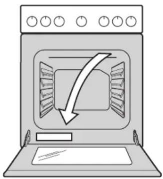
The rating plate is located on the lower left front frame of the appliance after opening the door. Alternate location may be under cooktop.
When ordering parts for or making inquires about your cooktop, always be sure to include the model and serial numbers and a lot number or letter from the rating plate on your cooktop.
Rating Plate Location:
natural_image
Illustration of a microwave oven with a downward arrow indicating cooling or ventilation (no text or symbols)Fig. 19

natural_image
Simple line drawing of a person with a lightning bolt symbol crossed by two wires (no text or labels)
natural_image
Illustration of two workers, one holding a box with a lightning bolt symbol, the other standing beside a box (no text or symbols present)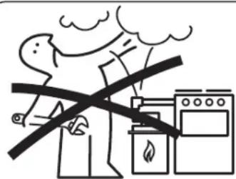
natural_image
Simple line drawing of two figures, one holding a tool and the other standing beside a stove with flames (no text or symbols)

natural_image
Two stylized human figures standing on wooden blocks, one crossed with a hammer and the other holding a hammer, both without any text or symbols.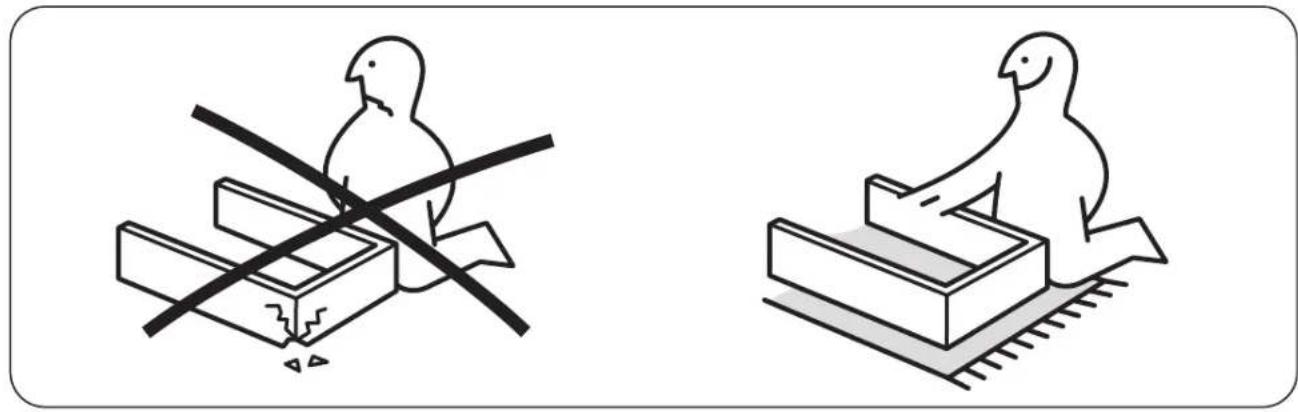
natural_image
Two line drawings of birds on different platforms: one with a crosshair and bird, the other with a bird on a platform (no text or symbols)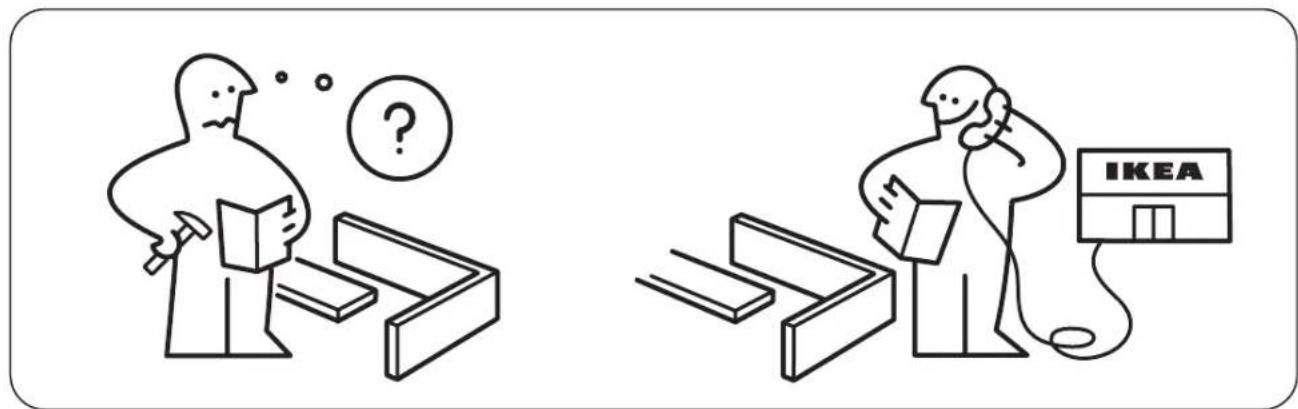
natural_image
Simple line drawing of a circular mechanical component with flanges and a small protrusion at the end (no text or symbols)Fig. d
natural_image
Illustration of a hand using a power drill on a cutting board (no text or symbols)Fig. 6
natural_image
Close-up of a hand using a tool to adjust or install a mechanical component, no visible text or symbols.Fig. 9
natural_image
Close-up of a mechanical assembly with a wrench tool inserted, no visible text or symbolsFig. 10
g. Check for gas leaks. Turn the gas supply on to the range and use a liquid leak detector at all joints and conduits to check for leaks in the system.
natural_image
Diagram showing a screwdriver and two mechanical components with a directional arrow (no text or symbols)Fig. 17
natural_image
Illustration of a kitchen oven with a downward arrow indicating airflow or ventilation (no text or symbols)Fig. 19

UN INSTALLATEUR QUALIFIÉ DOIT EFFECTUER L'INSTALLATION ET LE SERVICE. IMPORTANT: CONSERVEZ CES INSTRUCTIONS POUR LES INSPECTEURS LOCAUX. LISEZ CES INSTRUCTIONS ET CONSERVEZ-LES POUR RÉFÉRENCES ULTÉRIEURES.
AVERTISSEMENT!
natural_image
Simple line drawing of a person with a lightning bolt symbol crossed by two wires (no text or labels)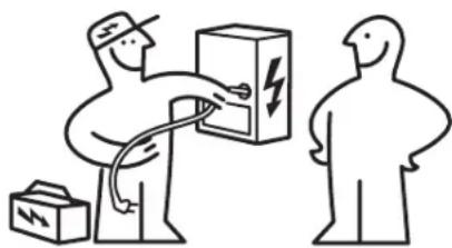
natural_image
Illustration of two figures interacting with a box, one holding a cable and the other holding a package (no text or symbols)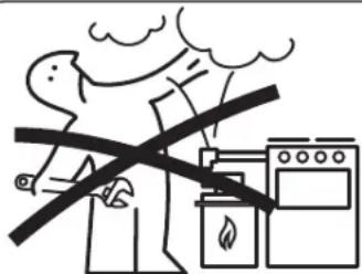

natural_image
Simple line drawing of two figures, one holding a tool and the other standing beside a stove with flames (no text or symbols)
natural_image
Two stylized human figures standing on wooden blocks, one crossed with a hammer and the other holding a hammer, both without any text or symbols.
natural_image
Two line drawings of birds on different platforms, one with a crosshair and the other with a smiley face (no text or symbols)
Outils nécessaires
natural_image
Simple line drawing of a circular mechanical component with two side connectors (no text or symbols)natural_image
Illustration of a hand using a drill pen to cut or mark a tool on a cutting board (no text or symbols present)Fig. 6
natural_image
Close-up of a hand using a tool to adjust or install a mechanical component, no visible text or symbols.Fig. 9
natural_image
Close-up of a mechanical assembly with metal components and bolts (no visible text or symbols)Fig. 10
natural_image
Hand holding a gray sphere with directional arrows indicating rotation or movement (no text or symbols)Fig. 16
natural_image
Two views of a circular mechanical component with a ruler above it (no text or symbols visible)natural_image
Technical illustration of a tool and component assembly (no text or symbols)Fig. 17
natural_image
Illustration of a kitchen oven with a downward arrow indicating airflow or cooling (no text or symbols)Fig. 21