
2152-5 - Remote control Hazet - Free user manual and instructions
Find the device manual for free 2152-5 Hazet in PDF.

| Product type | Automotive diagnostic remote control |
| Brand | Hazet |
| Model | 2152-5 |
| Rated voltage | 12-24 V |
| Power supply | Vehicle battery via clamps |
| Cable length | 6 m |
| Display | Red/green LED |
| Acoustic signal | Yes, differentiated positive/negative |
| Integrated light | Yes, for dark areas |
| Main functions | Polarity test, continuity, short circuits, ground contacts, component power supply |
| Protection | Resettable circuit breaker, short-circuit protection |
| Maintenance and cleaning | Wipe with a dry cloth, do not use chemicals |
| Safety | Do not use on 110/230 V circuits, nor near flammable substances |
| Spare parts and repairability | Replacement cable available, repairs reserved to the manufacturer |
| General information | Compliant with CE standards, professional automotive use |
Frequently Asked Questions - 2152-5 Hazet
User questions about 2152-5 Hazet
0 question about this device. Answer the ones you know or ask your own.
Ask a new question about this device
Download the instructions for your Remote control in PDF format for free! Find your manual 2152-5 - Hazet and take your electronic device back in hand. On this page are published all the documents necessary for the use of your device. 2152-5 by Hazet.
USER MANUAL 2152-5 Hazet
HIGHEST TECHNOLOGY IN TOOL MANUFACTURE SINCE 1868

2152-5

Betriebsanleitung
Operating Instructions
Electrical Multifunctional Testing Device
natural_image
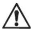
Exterior view of a blue HAZET 250-E electrical testing device connected to a black and red wire with two metal clips (no text or symbols visible on the main subject)Table of Contents Operating Instructions HAZET 2152-5 Page
Lighting and audible signal....22
Connecting and Self-Testing....23
Polarity Test....24
Continuity Test 25
Activating components of the electrical system of the car....26
Testing trailer lights and connections....27
Activating components with positive (+) voltage....28
Activating components with negative (-) voltage....29
Jumper lead function....30
Detecting bad ground contacts ....31
Following-up and locating short circuits....31
How to avoid blowing fuses....32

33-47
natural_image
Line drawing of a simple electrical circuit with a cart, battery, and power supply (no text or symbols)
- Please take care that the user of this testing device carefully reads these operating instructions and understands all information given in there before the first use.
- These operating instructions contain important advices that are necessary for a safe and trouble-free operation of your HAZET testing device.
- For effective use of the testing device as intended, it is essential that all safety and other information in these operating instructions is adhered to.
- For this reason, always keep these operating instructions together with your HAZET testing device.
- This testing device has been designed exclusively for particular applications. HAZET emphasizes that any modification of this device and/or an application that does not correspond to its intended application is strictly forbidden.
- HAZET will not be liable for any injuries to persons or damages to property that are due to an improper application or misuse of this tool respectively due to the disregard of the safety instructions.
- Furthermore, the general safety regulations and regulations for the prevention of accidents being valid for the application area of this device have to be observed, too.
2. Explanation of Symbols
ATTENTION: Please pay attention to these symbols!
Read the Operating Instructions!

The operator is obliged to observe the operating instructions and has to instruct all users of the testing device according to the information given in this manual.
NOTICE!

This symbol marks indications which help you to use the device.
CAUTION!

This symbol marks important specifications, dangerous conditions, safety risks and safety advices.
ATTENTION!

This symbol marks indications whose disregard results in damage, malfunction and or functional failure of the device.
3. Liability and Warranty
- Any deviation from the intended use and/or any misapplication of the testing device is not allowed and will be considered as improper use.
- Any claims against the manufacturer and/or its authorized agents because of damage caused by improper use of the testing device are excluded.
- Any personal injury or material losses caused by improper use are the sole responsibility of the operator and user.
4. Disposal
- For disposal, disassemble device according to regulations for environmental protection and for work safety. Components can be recycled.
• Metallic components can be scrapped. - Components made of plastic can be recycled according to regulations for recycling of plastics.
- Recycle other components according to the regulations applying to their composition.

Do not use on electronic control units!
This paragraph gives an overview about all important security advices which help to ensure the optimal protection of the personnel as well as the safe and trouble-free operation of the testing device.
Additionally, the different chapters contain concrete security advices that are marked with symbols in order to avert immediate danger.

1. General Aspects
- The testing device was developed and fabricated according to the technical norms and standards that have been valid at that time and is considered to be operationally re liable. Nevertheless, the device can present a danger when it is not used as intended or in an inappropriate way by non-qualified personnel. Please take care that any person using the device or carrying out maintenance work carefully reads these operating instructions and understands all information given in there, before the first use.
- Any modification of the testing device is strictly forbidden.
2. Operator's Liability
- Keep the operating instructions always together with the testing device.
- The testing device must only be used if it is technically faultless and operationally reliable.
- All security devices must always be within reach and should be checked regularly.
- Apart from the safety advices given in these operating instructions, the user of this tool has to observe and respect the safety regulations, regulations for the prevention of accidents and regulations for environmental protection being valid for the application area of this device, too.

3. Appropriate Use
Operational safety can only be guaranteed, if the device is used as intended and in compliance with the indications given in the operating instructions. Apart from the safety advices given in these operating instructions, the general safety regulations, regulations for the prevention of accidents and regulations for environmental protection being valid for the application area of this testing device have to be observed and respected, too.
The testing device has to be used, inspected and main tained always in compliance with the respective local, state, national or federal regulations.
- The electrical multifunctional testing device with LED and integrated lighting is intended for testing electrical components.
- Any deviation from the intended use and/or misapplication of the testing device is not allowed and will be considered as improper use.
- Any claims against the manufacturer and/or its authorized agents because of damage caused by improper use of the device are excluded.
- Any personal injury or material losses caused by the improper use are the sole responsibility of the operator and user.

The electrical multifunctional testing device HAZET 2152-5 is a tester which reduces the time needed for checking automotive electrical systems from 12 to 24 volts. After connecting the testing device to the battery, the motorcar mechanic can determine by one glance at the red/green LED if the electrical circuit is positive, negative or open without having to release the feeder clamps from the battery. The rocker switch allows the car mechanic to conduct a positive or negative current to the tip in order to test the functioning of electrical components. The device is protected against short circuits. It allows to detect and locate bad ground contacts instantly without performing voltage drop tests. It allows to follow-up and locate short circuits without having to waste precious fuses. The multifunctional testing device can also be used for continuity tests (for this purpose use the negative auxiliary clamp, too). By touching the rocker switch you will find out at once if the testing device is functioning. The 6 m cable allows to test the complete electrical system of the car without having to search constantly for the ground contacts.
Please read the operation instructions carefully before using the testing device.

While operating the rocker switch battery current is directly conducted to the tip which may cause sparks when contacting ground or certain circuits. Therefore, the electrical multifunctional testing device must not be used close to flammables such as gasoline or its vapors. The spark of a current-carrying testing device can ignite such vapors. Please observe the same safety advices as in case of using e.g. an arc welder.

The HAZET electrical multifuncional testing device 2152-5 must not be

used with 110/230 volt house current. It is only intended for use with 12 to 24 volt systems. Any claims against the manufacturer because of improper use are void.

Important notice:
You can increase the life of your multifunctional testing device if, while testing components, you operate the rocker switch before connecting the tip to the component. The arcing will take place at the tip rather than at the switch contacts.
③ Design and Function


Do not use on electronic control units!
Multifunctional testing device 2152-5 with optical and audible signal functions
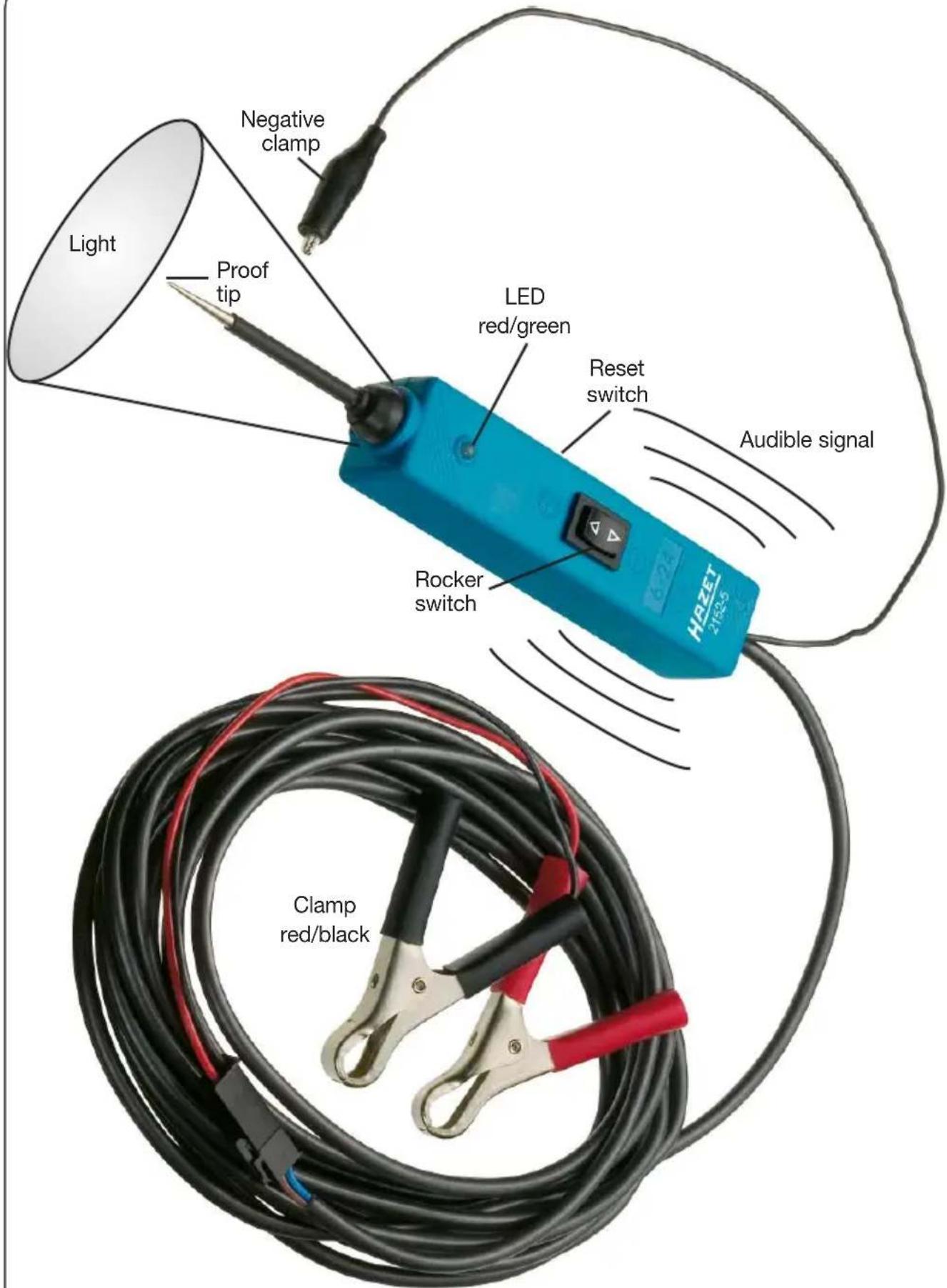
HAZET 2152-5 is equipped with an optical and an audible signal function. After connecting it to a battery, the optical and audible signals are activated.
- The testing area is lit which is very helpful for working in dark areas.
- The polarity signal is enforced by the audible signal. If the tip contacts a positive circuit, there is a permanent signal. If the tip con tacts a negative circuit, there is a pulse signal.
POSITIVE = permanent signal NEGATIVE = pulse signal

Do not use on electronic control units!
③ Design and Function
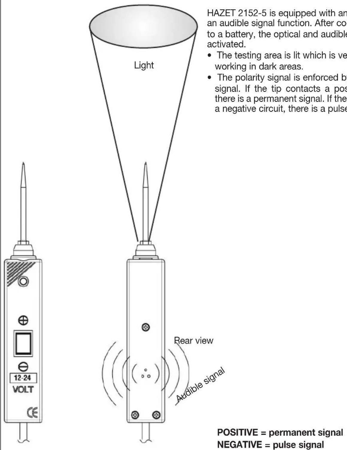
Connecting
First connect the testing device to the battery.
- Unroll the cable.
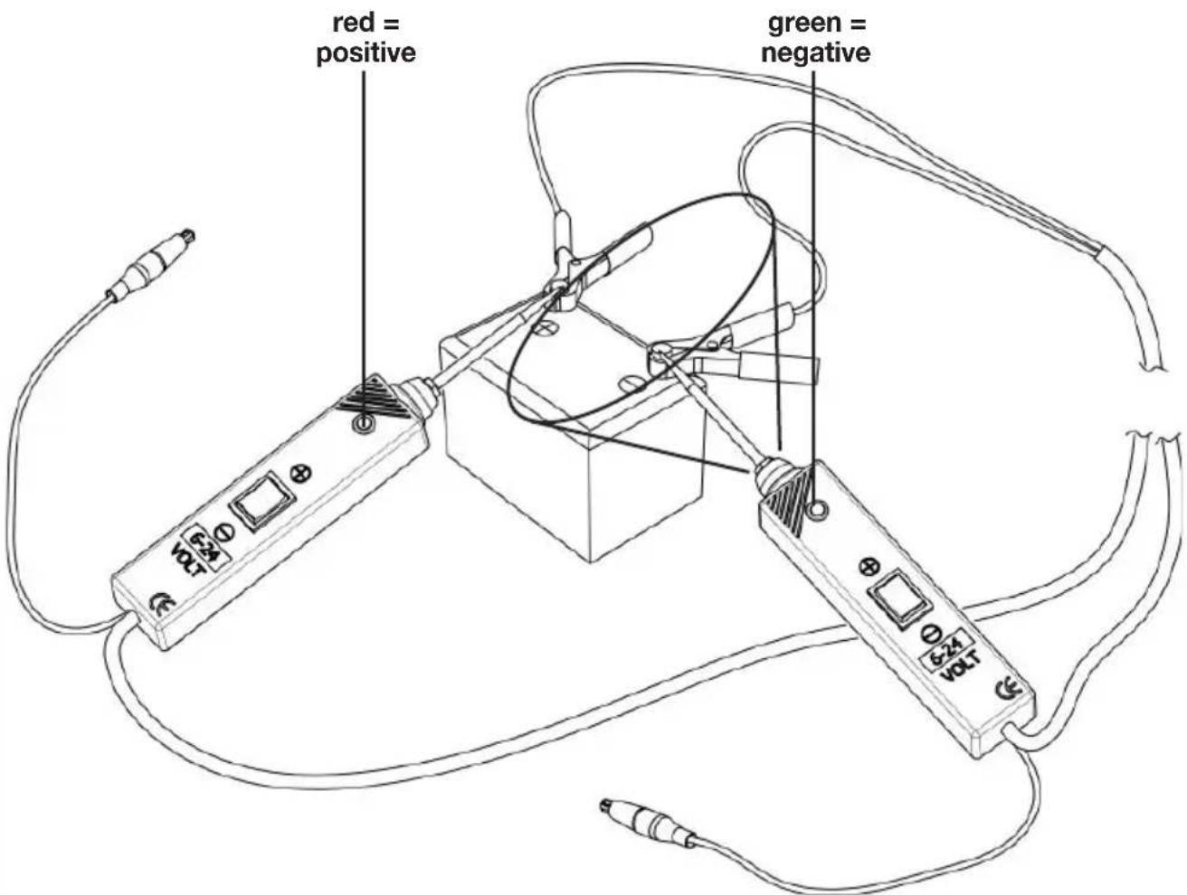
- Connect the red clamp to the positive pole of the battery
- Connect the black clamp to the negative pole of the battery
If you want to use the extension cable, disconnect the adapter of the battery clamp and put the extension cable in between.
Self testing
- Push the rocker switch forward (+). The light (LED) should be red.
- Push the rocker switch backward (-). The light (LED) should be green.
• The testing device is ready for use.
If the LED is off, push the reset switch (on the side) and start self testing again.
Polarity test

Do not use on electronic control units!
en
③ Design and Function
- If the tip of the testing device contacts a positive circuit, the LED is red.
- If the tip of the testing device contacts a negative circuit, the LED is green.
- If the tip of the testing device contacts an open circuit, the LED is off.

Do not use on electronic control units!
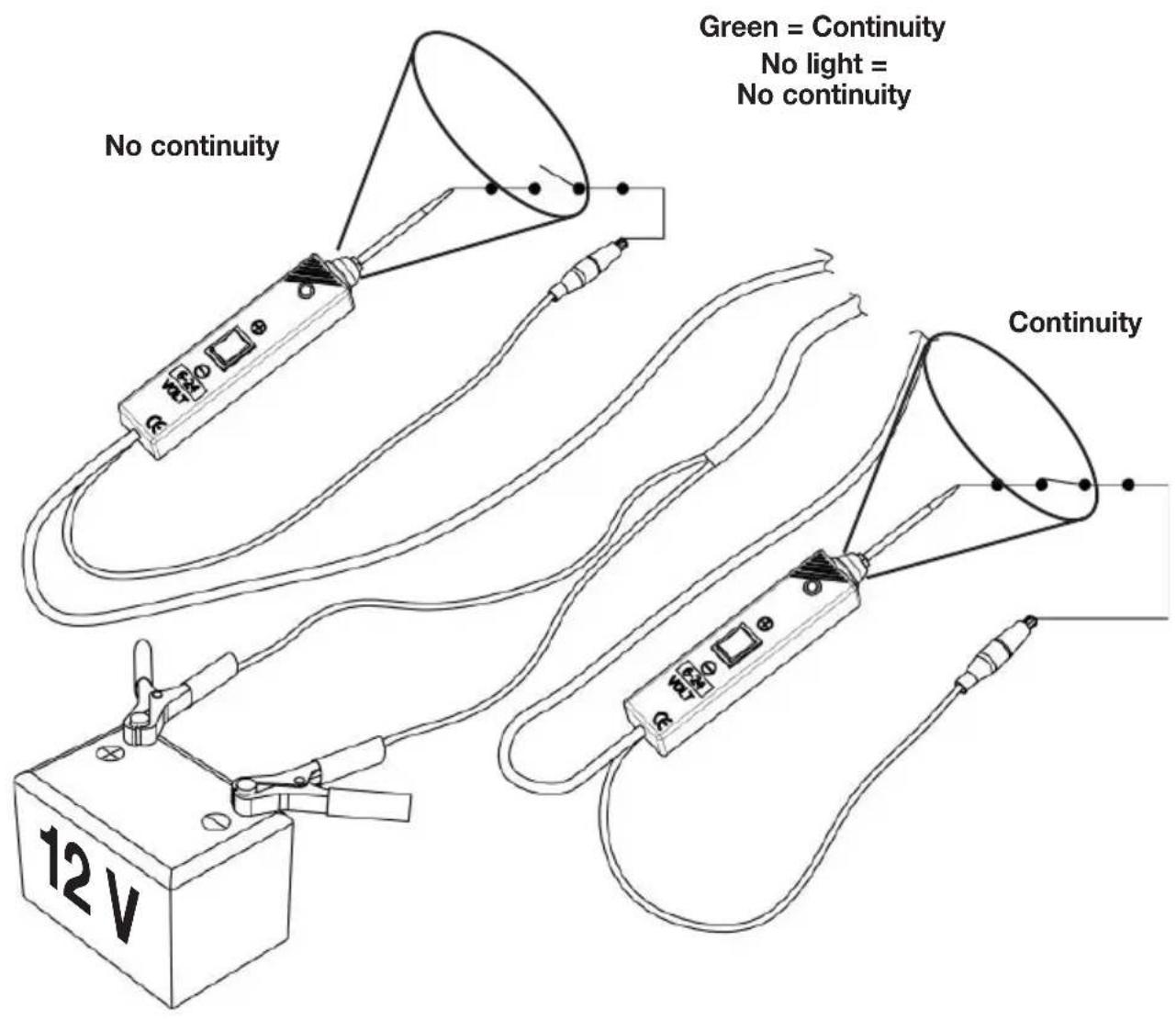
Continuity test
For checking the continuity of a component (wire, cable, switch, etc.), it has to be disconnected from the electrical circuit of the car.
- Connect the negative clamp to the component and check the continuity with the tip.
- The continuity is confirmed by a green LED.
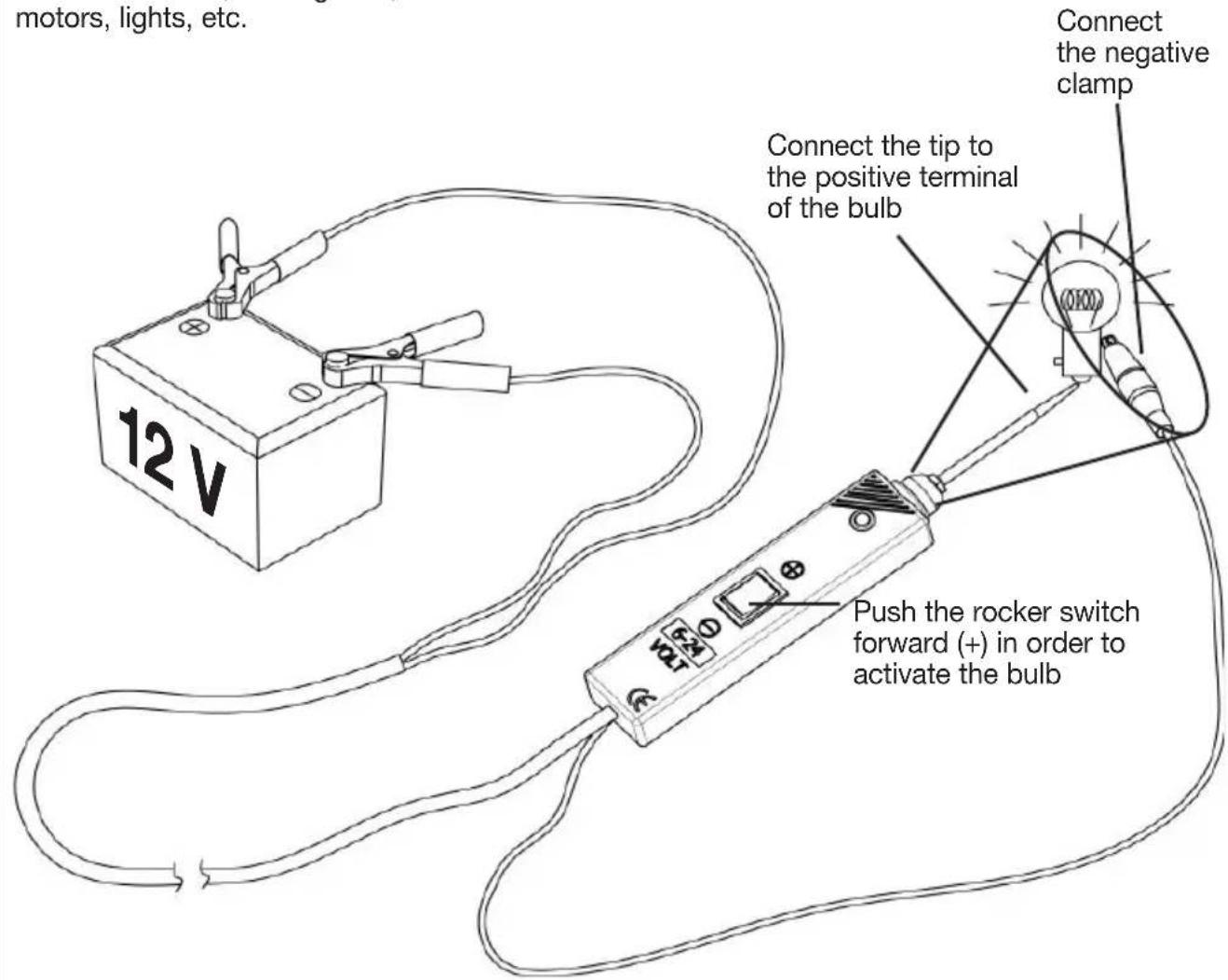
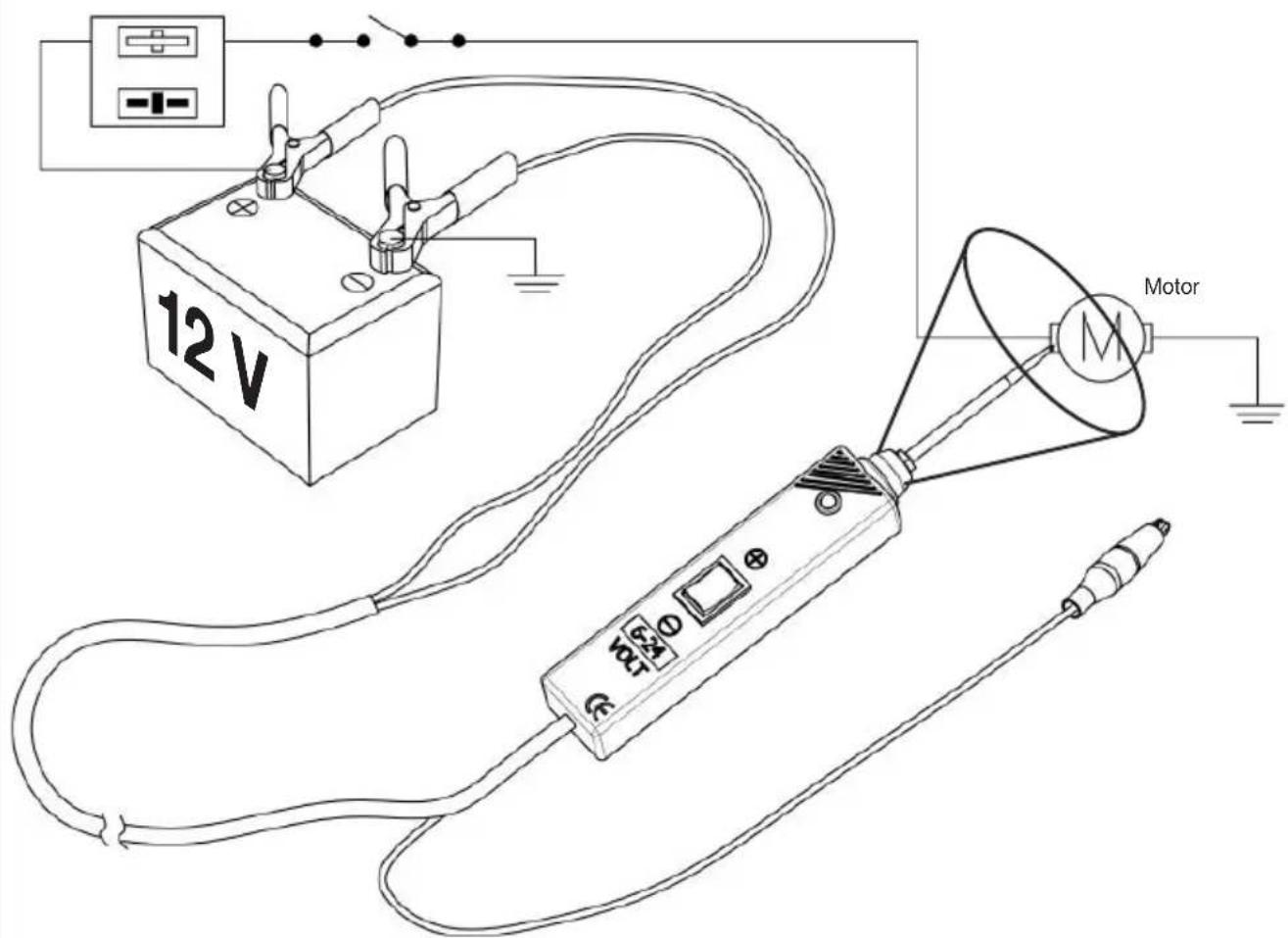
Activating components outside the electrical system of the car
If the multifunctional testing device is used with an auxiliary ground lead, components can be activated and their function can be tested.
- Connect the negative clamp to the negative terminal of the component being tested.
- Connect the proof tip to the positive terminal of the component. The LED is GREEN indicating continuity for the component.
-
Watch the LED and push the rocker switch forward (+) and immediately release it again. If the LED changes without delay from GREEN to RED, you may continue. If the green LED extinguishes or if the circuit breaker is released, the testing device is overloaded. This could be due to the following reasons:
-
The contact is a direct ground contact or its circuit is negative.
- The component has a short circuit.
- The component is a high amperage component (e.g. starter motor).
If the circuit breaker has been released, push the reset button.
Activate fuel pumps, magnetic clutches, starter solenoids, cooling fans, blower motors, lights, etc.

Do not use on electronic control units!
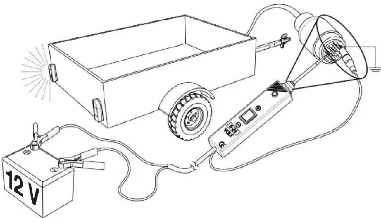
Testing trailer lights and connections
- Use the negative clamp for setting up a ground connection.
- Connect the proof tip to the different trailer elements and lamps. Check the connection of the plugs to the lamps and detect their classification.
- If the circuit breaker has been released, there is a ground connection.
- If the circuit breaker has been released, reset by using the reset button.
natural_image
Line drawing of a simple electrical experiment setup with a cart, power supply, and detection device (no text or symbols)Activating electrical components with positive (+) voltage
- Connect the proof tip to the positive terminal of the component. The LED is green.
-
Watch the LED and push the rocker switch forward (+) and immediately release it again. If the LED changes without delay from GREEN to RED, you may continue. If the LED extinguishes or if the circuit breaker is released, the testing device is overloaded. This could be due to the following reasons:
-
The contact is a direct ground contact.
- The component has a short circuit.
- The component is a high amperage component (e.g. starter motor).
If the circuit breaker has been released, push the reset button.

Caution: If voltage is applied to certain circuits, this may cause damage to the electrical components of the car. Therefore, it is strongly recommended to use the corresponding circuit diagram and the appropriate diagnosis procedure for the test.

Important notice: You can increase the life of your multifunctional testing device if, while testing components, you operate the rocker switch before connecting the tip to the component. The arcing will take place at the tip rather than at the switch contacts.

Do not use on electronic control units!
Activating electrical components with negative (-) voltage
- Connect the proof tip to the negative terminal of the component. The LED is red.
-
Watch the LED and push the rocker switch back (-) and immediately release it again. If the LED changes without delay from RED to GREEN, you may continue. If the LED extinguishes or if the circuit breaker is released, the testing device is overloaded. This could be due to the following reasons:
-
The contact is a direct positive current.
- The component has a short circuit.
- The component is a high amperage component (e.g. starter motor). If the circuit breaker has been released, push the reset button.
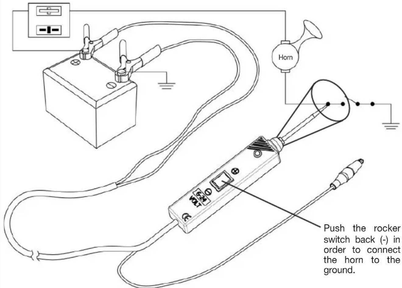
Push the rocker switch back (-) in order to connect the horn to the ground.
③ Design and Function
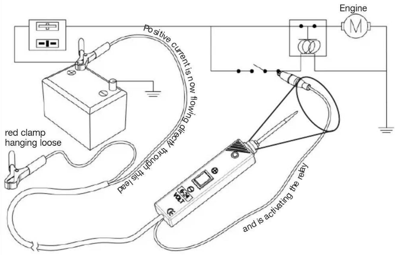
Jumper lead function
For using the testing device as jumper lead:
- Connect the black clamp to the (+) pole of the car battery
- The black clamp is directly connected to the jumper lead
• The red clamp has no particular function here

Caution! Avoid short circuits in this function. The leads are not protected by the circuit breaker! The device can be damaged.

Do not use on electronic control units!
Detecting bad ground contacts
Mostly, the reason for a bad ground contact is a loose cable connection, a loose cable in the lug or an oxidized contact. Such defects can only be detected by a voltage drop. However, the necessary tests are very time-consuming.
With the multifunctional testing device you can detect bad ground contacts without such tests.
Connect the multifunctional testing device to the car battery (see on page 21).
Connect the proof tip to the presumably bad contact. The LED is green (continuity to ground).
- Push the rocker switch forward (+) and watch the LED.
- If the LED changes from GREEN to RED, the ground contact is bad.
- If the circuit breaker is released, the ground contact is fine.
Following-up and locating short circuits
- Start searching for the short circuit in the fuse box.
- Remove the fuse from the fuse box.
- Use the testing device to direct positive current to each of both contacts in the fuse box. At the side of the short circuit the circuit breaker of the testing device is released.
- Follow the cable through the cable harness as far as possible.
- Pull the cable out of the cable harness and engrave with the proof tip. The LED is green.
- Push the rocker switch forward (+) to find out if you pulled out the appropriate cable (circuit breaker must release).
- Cut the cable and direct current to each extremity of the cable. The circuit breaker is released again on the side of the short circuit.
- Repeat this process until the short circuit is located.
③ Design and Function
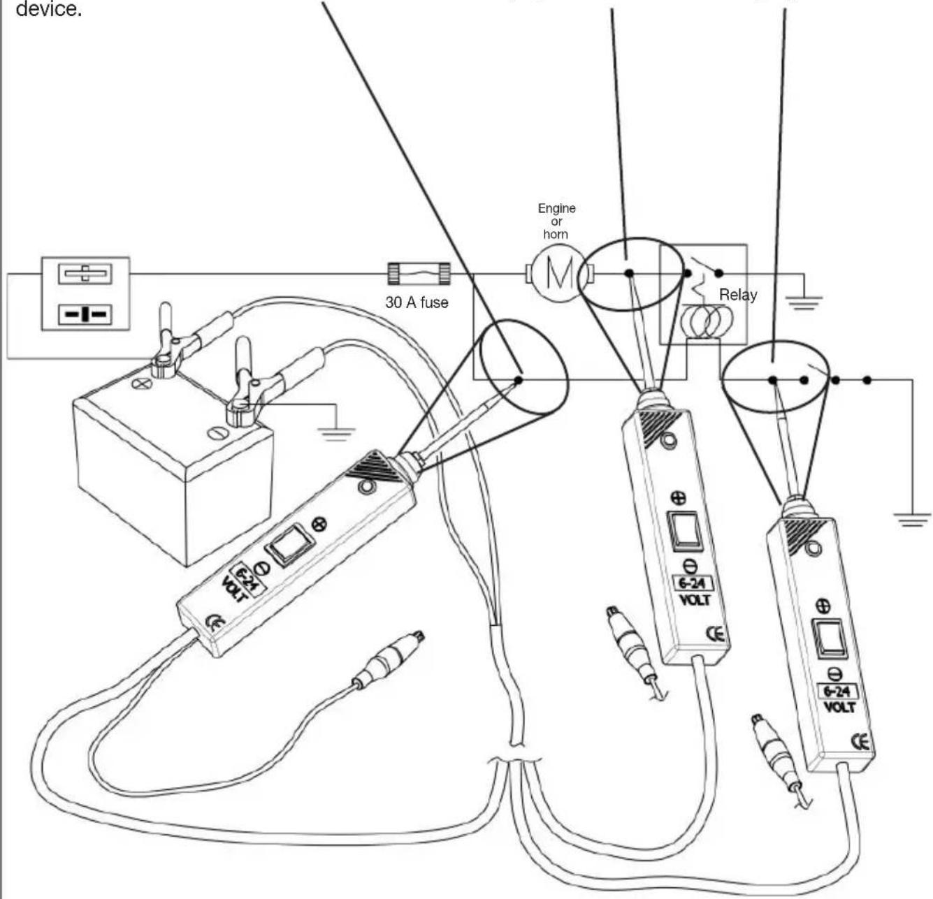
How to avoid blowing fuses
Due to the increased power rating of the testing device, there is more current flowing when the switch is operated. You will find out that the testing device is supplying higher nominal current to the electrical devices.

Caution: Grounding a positive circuit with the testing device can blow a fuse, if the fuse is connected directly in series to the circuit being grounded. Please see figure.
In this circuit the 30 A fuse can blow if the rocker switch is pushed backwards (-). Make sure that the fuse is connected to the device.
This circuit can be ground without destroying the fuse.
This circuit can be ground without destroying the fuse.

Do not use on electronic control units!

POSITIF = signal constant
natural_image
Line drawing of a simple electrical circuit with a cart, battery, and power supply (no text or symbols)