
Pinguino Smart PACEL140LRFK-3ALBK - Air Conditioning DELONGHI - Free user manual and instructions
Find the device manual for free Pinguino Smart PACEL140LRFK-3ALBK DELONGHI in PDF.

| Product Type | Portable monoblock air conditioner |
| Brand | De'Longhi |
| Model | Pinguino Smart PACEL140LRFK-3ALBK |
| Power Supply | 115 V ~ 60 Hz |
| Refrigerant | R410A (GWP=2088) |
| Main Functions | Air conditioning, dehumidification, ventilation |
| Specific Technology | ECO REAL FEEL (combined temperature/humidity control) |
| Connectivity | Built-in Wi-Fi, control via De'Longhi app |
| Remote Control | Yes, with AAA batteries (2 x 1.5 V) |
| Display | LED digital display |
| Temperature Units | °C or °F (selectable) |
| Cooling Capacity | Approximately 14,000 BTU/h (presumed from model) |
| Dehumidification | Yes, with automatic drainage |
| Fan Speeds | 3 speeds (low, medium, high) |
| Self-Evaporation | Yes, in cooling and dehumidification modes |
| Compressor Protection | 3-minute delay before restart |
| Air Filter | Washable, weekly cleaning recommended |
| Installation | Wall or window mounting (kit included) |
| Accessories Included | Exhaust hose, wall flange, window bracket, remote control, drain hose |
| Dimensions (approx.) | Approximately 45 x 35 x 70 cm (W x D x H) |
| Weight (approx.) | Approximately 30 kg |
Frequently Asked Questions - Pinguino Smart PACEL140LRFK-3ALBK DELONGHI
User questions about Pinguino Smart PACEL140LRFK-3ALBK DELONGHI
0 question about this device. Answer the ones you know or ask your own.
Ask a new question about this device
Download the instructions for your Air Conditioning in PDF format for free! Find your manual Pinguino Smart PACEL140LRFK-3ALBK - DELONGHI and take your electronic device back in hand. On this page are published all the documents necessary for the use of your device. Pinguino Smart PACEL140LRFK-3ALBK by DELONGHI.
USER MANUAL Pinguino Smart PACEL140LRFK-3ALBK DELONGHI
Instructions for use. Keep these instructions
Visit www.delonghi.com for a list of service
centers near you.
ELECTRIC CHARACTERISTICS
115 V\~60 Hz
natural_image
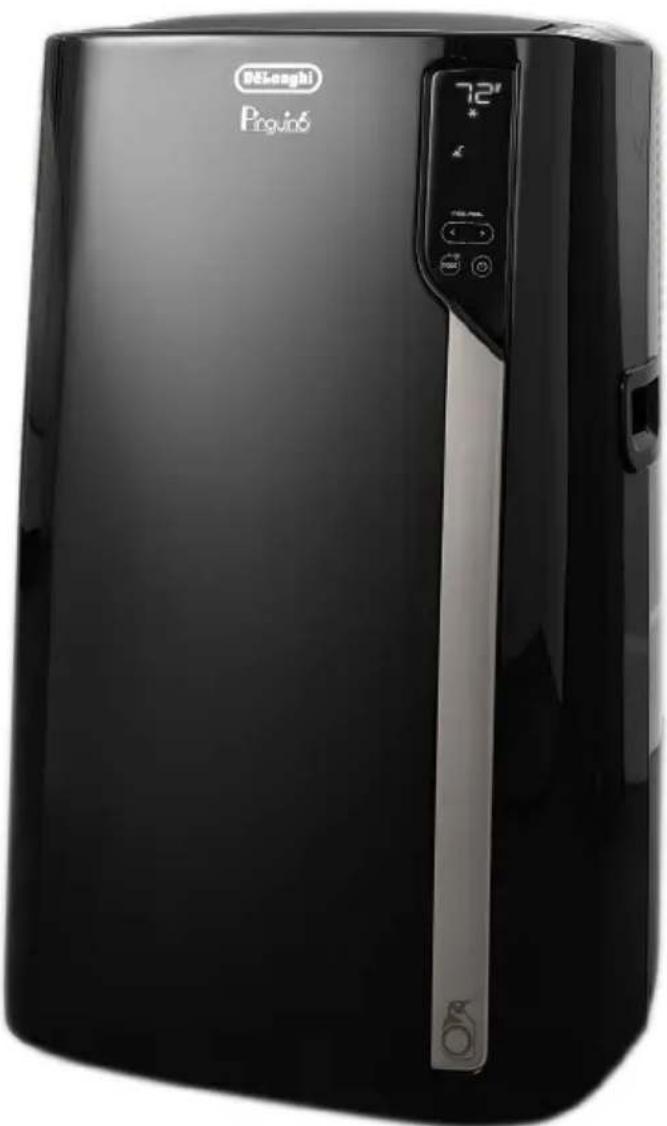
Black industrial air purifier device with digital display and control buttons (no visible text or symbols on body)CONDITIONNEUR D'AIR PORTATIF
natural_image
Simple line drawing of an open book with multiple pages (no text or symbols)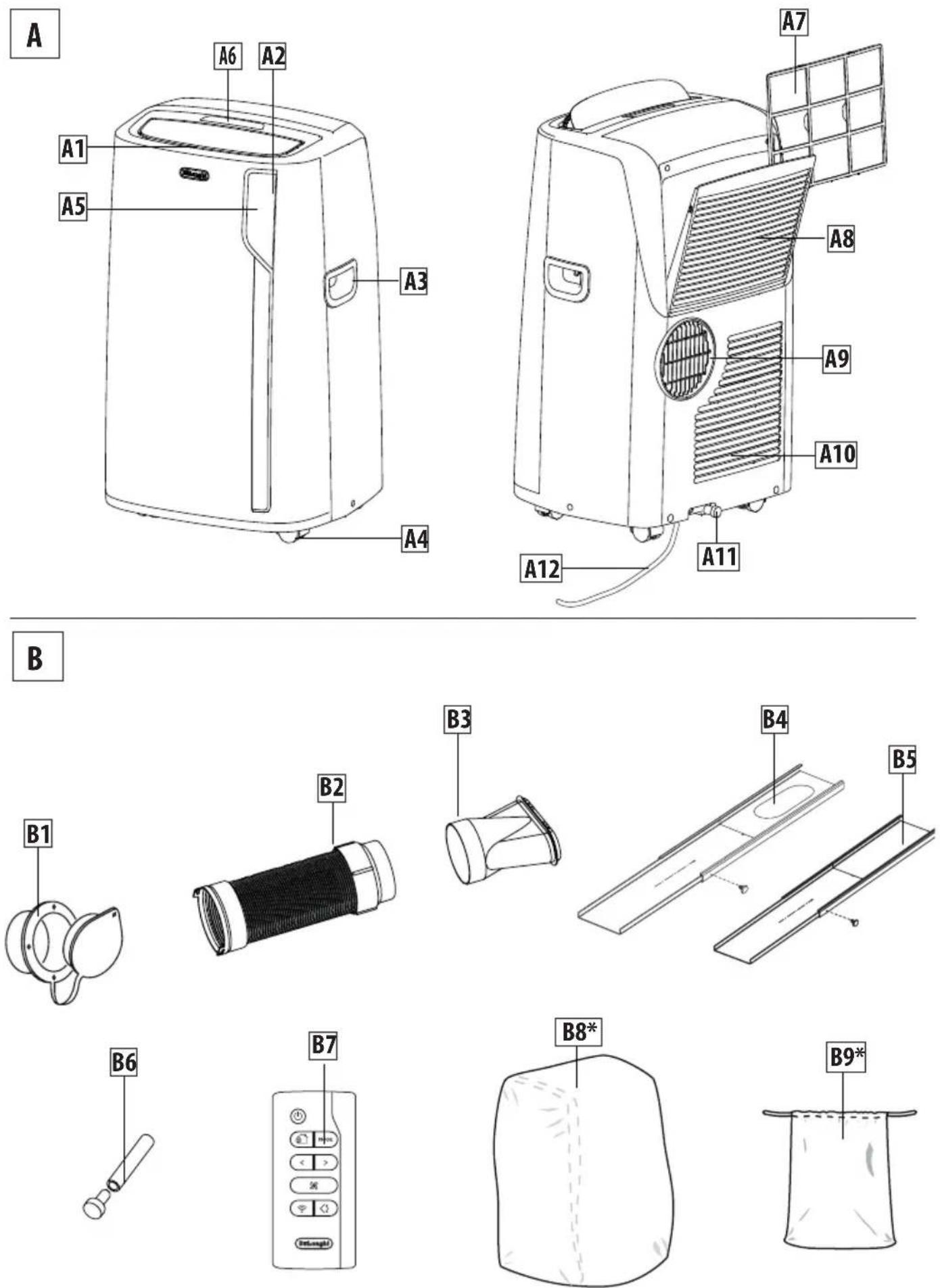
Important safeguard
- Use this appliance only as described in this instruction manual.
As with any electrical appliance, the instructions aim to cover as many situations as possible. Caution and common sense should be used when operating and installing this air conditioner.
- This appliance has been manufactured to cool and dehumidify domestic environments and must not be used for other purposes.
- It is dangerous to alter or modify the unit's characteristics in any way.
- The appliance must be installed in accordance with the relevant national legislation.
- Should repairs be necessary, contact our toll free customer service at 1-800-322-3848. Unauthorized servicing can be dangerous.
- The appliance is not intended for use by persons (including children) with reduced physical, sensory or mental capabilities, or lack of experience and knowledge, unless they have been given supervision or instruction concerning use of the appliance by a person responsible for their safety.
Children should be supervised to ensure that they do not play with the appliance.
- If the power cable is damaged, it must be replaced by the manufacturer or an authorized technical service centre in order to avoid all risk.
- Always ensure the appliance is plugged into a grounded 3-prong outlet. If you have any doubts check with a qualified electrician.
- Do not use extension cables.
- Before cleaning or maintenance operations, always unplug the unit from the outlet.
- Do not pull on or place strain on the power cord when moving the appliance.
- The appliance should not be installed where the atmosphere may contain combustible gases, oil or sulphur, or near heat sources.
- Do not rest hot or heavy objects on the appliance.
-
Clean the filters at least once a week.
-
Avoid using heaters near the unit.
- The unit should be transported in a vertical position. If this is not possible secure the unit at an angle, do not lie it horizontally.
- Before transporting the unit, drain the unit. After transportation, wait at least 6 hours before switching the unit on.
- The packaging materials can be recycled. You are therefore recommended to place them in the special containers for differentiated waste collection.
- This appliance is fitted with a special safety device. When the compressor switches off, this device prevents it from switching on again for at least 3 minutes.
- WARNING: Changes or modifications not expressly approved by the party responsible for compliance could void the user's authority to operate the equipment.
Specific warnings for appliances with R410A refrigerant gas
R410A is a refrigerant that complies with European eco logical standards; nevertheless, it is recommended not to pierce the cooling circuit of the machine. At the end of its useful life, deliver the appliance to a special waste collection centre for disposal.
This hermetically sealed system contains fluorinated greenhousegases.
ENVIRONMENTAL INFORMATION:
This unit contains fluorinated greenhouse gases covered by the Kyoto Protocol.
Maintenance and disposal must be carried out by qualified personnel only (R410A, GWP=2088).
Save these instructions
This product is for household only
INTRODUCTION
Thank you for choosing a De'Longhi product. Please take a few moments to read the instructions to avoid risks or damage to the appliance.
Download the App!

natural_image
Icon of a snowflake inside a refrigerator, labeled 'DE'LONGHI' below (no additional text or symbols)
This appliance can be used also with the App Pinguino that can be downloaded from the App Store® or from Google Play.
To gain access to all functions you need a local net (Home WLAN) with access to Internet. Further check there are no obstacles to the Internet access, such as Firewall, Proxy, authentications, etc.,
DESCRIPTION
Description of the appliance (See page 3 - A)
A1. Air outlet grid
A2. Control panel
A3. Handles
A4. Wheels
A5. Remote control signal receiver
A6. Remote control storage
A7. Filter
A8. Air intake grille
A9. Air exhaust hose housing
A10. Air intake grille
A11. Drainage hose with cap
A12. Power supply cable
Description of accessories (See page 3 - B)
B1. Wall flange with cap
B2. Air exhaust hose
B3. Window outlet
B4. Window bracket with pins
B5. Additional window bracket with pins
B6. Water drain hose with cap
B7. Remote control
B8. End of season dust cover (*only on some models)
B9. End of season accessories bag (*only on some models)
Electrical connection
Before plugging the appliance into the outlet, check that:
•Theoutlet'spowersupplycorrespondstothevalue indicated on the rating label on the back of the appliance;
- The outlet and electrical circuit are adequate for the appliance;
- The outlet is a 3-hole grounded outlet. If this is not the case, you must choose another outlet. Failure to follow these important safety instructions absolves the manufacturer of all liability.
If it becomes necessary, the power cable must be replaced by a qualified professional only.
The instructions below will enable you to prepare your air conditioner for operation as efficiently as possible. Before use, make sure the air intake and outlet grilles are unobstructed.
USE
Note: This appliance features an auto evaporative function to remove excess condensate water during cooling and dehumidifying modes.
CONDITIONING WITH INSTALLATION
For optimal results set-up your appliance in this way:
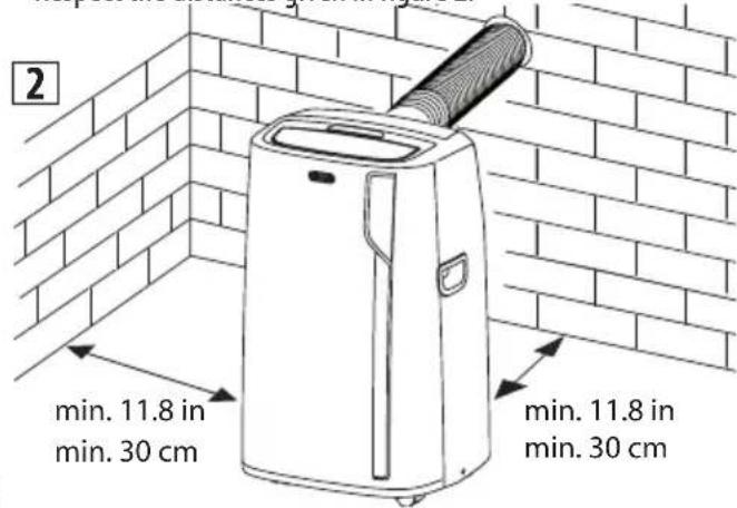
- Fit the assembled air exhaust hose B2 in the housing at the back of the appliance. Insert it as shown in figure 1.

natural_image
Technical illustration of a turbocharger assembly showing airflow direction and component details (no text or symbols)• Respect the distances given in figure 2.
- Drill a hole ∅ 5,25 inches (134 mm) in an outside wall or through a wooden kickboard. Respect the dimensions and height of the hole given in figure 3 and 4.
3
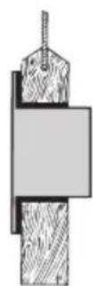
in the wooden kickboard of a French window or panel
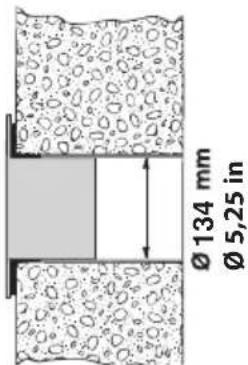
in the wall: you are recommended to insulate the section of wall using suitable insulation
• Fit the wall flange B1 into the hole.
- Fit the hose B2 into the wall flange B1 as shown in fig. 4.
- When the hose B2 is not connected, the drilled hole can be closed with the flange cap B1.
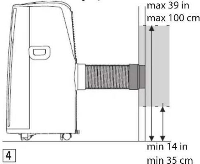
- When installing the air conditioner, you should leave a door slightly open little as 1/2" (1 cm) to guarantee correct ventilation and room pressure.
- Keep the air hoses as short and free of curves as possible to avoid constrictions.
Note:
- Asspecialtoolsarerequiredforthistypeof installation, we suggest you have the appliance installed by specialized personnel.
CONDITIONING WITHOUT INSTALLATION
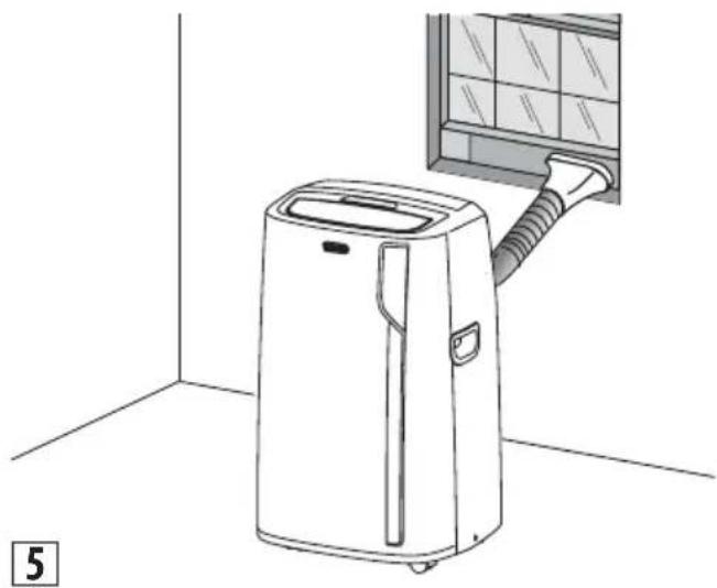
You can also set-up in a double-hung window:
- Place the window bracket in the window sill, extend the bracket fully within the window frame, fix the bracket by using the pin then lower the window onto the bracket. (Should the window bracket be too large for the window, the plastic can be cut with a saw by a qualified professional.)
- Fit the air exhaust hose B2 in the relevant housing located on the rear side of the appliance. (fig. 1).
- Connect the window outlet B3 to the other end of the exhaust hose.
- Insert the window outlet B3 of the exhaust hose into the slot of the window bracket (fig. 5).
natural_image
Line drawing of a small air conditioner unit connected to a wall-mounted grid panel (no text or symbols)Other set-up methods:
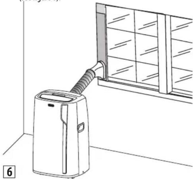
- Thanks to the locking pins, it's possible to use the window bracket also for sliding windows. Position the hole of the bracket so to allow a correct installation of the exhaust hose (see figure 6).
natural_image
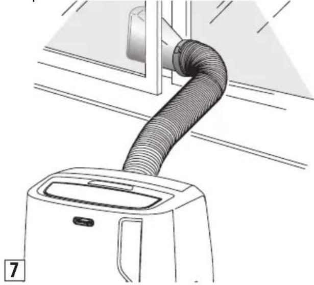
Line drawing of a small air conditioner unit connected to a window with a handle, no text or symbols present- If you have a casement window (figure 7) proceed as follows: - Fit the assembled air exhaust hose B2 in the relevant housing located on the rear side of the appliance, (fig. 1) then, apply the window outlet B3 to the air exhaust hose B2 and place it outside the window to exhaust the hot air.
natural_image
Line drawing of a hairless air conditioner with a coiled tube inserted into a device (no text or symbols)For help with installation, operation, and for all accessories and spare/replacement parts, please contact our toll free customer service call center at:
1-800-322-3848 [US only]
1-888-335-6644 [Canada only]
or log onto our website at www.delonghi.com
CONTROL PANEL
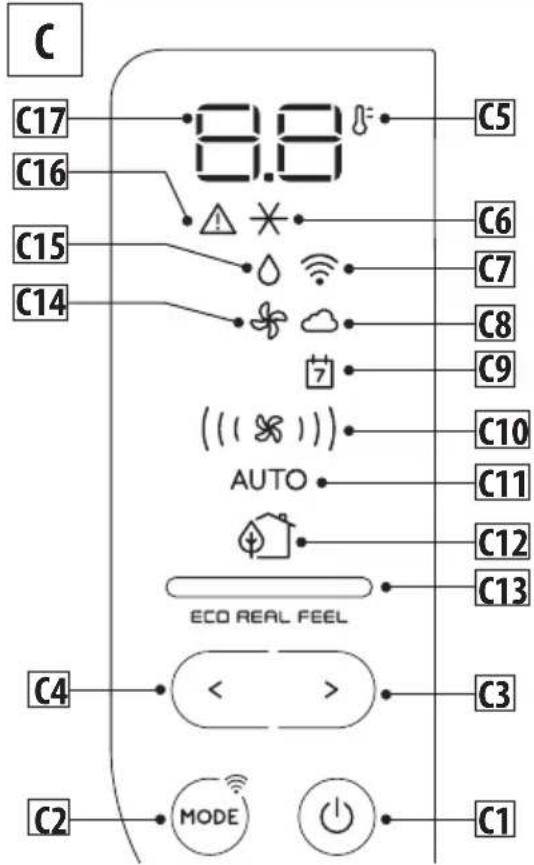
DESCRIPTION OF THE CONTROL PANEL (C)
C1. ON/STAND-BY (on/off) key
C2. Function selection key MODE (air conditioning, dehumidifying, fan, ON-OFF WiFi - reset WLAN settings)
C3. Increase key
C4. Decrease key
C5. Temperature indicator
C6. Air conditioning symbol
C7. WiFi symbol
C8. App indicator
C9. App timer/calendar
C10. Air flow indicator
C11. Auto indicator
C12. ECO REAL FEEL symbol (the function is available only from remote control and app)
C13. ECO REAL FEEL indicator
C14. Fan symbol
C15. Dehumidifying symbol
C16. Alarm symbol
C17. Set temperature values
TURNING THE APPLIANCE ON/OFF
Before plugging the appliance
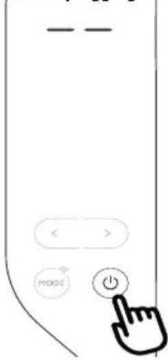
check the cap on back of the unit is correctly inserted on drainage hose A11.
Insert the plug in the socket.
Twodashesappearonthedisplay indicating that the appliance is in stand-by.
Touch the Ⓓ1 key to turn on the appliance.
When the appliance comes on, the last function set before it was shut off is activated.
NOTE: After few seconds of the control panel inactivity, its brightness
will be automatically reduced and in the next few minutes it will be further reduced.
To turn the appliance off, touch the ⏻key.
Note: Never turn off the air conditioner by simply pulling the plug. Touch the key in order to put your air conditioner in stand-by and wait a few minutes before pulling the plug. In this manner, the appliance can perform the operating status checks.
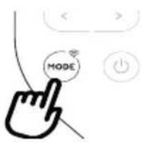
MODES SELECTION
To select the desired operating mode, touch repeatedly the MODE key until the desired function is selected.

WiFi FUNCTION
To select or deselect the Wifi function, keep touched the MODE key for 3 seconds.
\* AIR CONDITIONING MODE
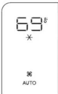
This is ideal for hot and humid weather when the room needs to be both cooled and dehumidified.
To correctly set this mode:
- Touch repeatedly the MODE key until the air conditioning symbol appears. The display will show the desired temperature.
- To change the temperature to be reached, touch the < C4 or >C3 key.
Note: In conditioning mode, the air flow can be selected only from the remote control and app.
DEHUMIDIFYING MODE
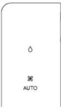
This is ideal for reducing humidity in the room (spring and autumn, damp rooms, rainy periods, etc). For this type of use, the appliance must be set up as for air conditioner mode. That is, the air exhaust hose B2 must be fitted to the appliance to allow the humidity to be discharged outside. To correctly set this mode:
- Touch repeatedly the MODE key until the dehumidifying symbol appears.
• The appliance automatically chooses the best air flow.
FAN MODE
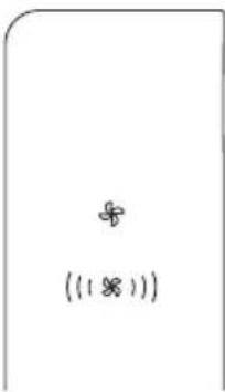
When using this mode, the air exhaust hose B2 does not need to be attached to the appliance.
To correctly set this mode:
- Touch repeatedly the MODE key until the fan symbol appears.
- Select the desired air flow by touching the increase > C3 or decrease < C4 keys.
The available air flows are:
Minimum air flow: when maximum silent operation is desired.
(18) Medium air flow: when the noise level needs to be low but with a good comfort level.
((18))) Maximum air flow: for maximum performance.
SELECT THE TEMPERATURE SCALE
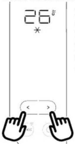
The temperature can be displayed in °C or °F.
To change the temperature unit of measure touch both the increase/decrease keys > D5 and < D4 for about 10 sec.
- Remove the cover on the rear of the remote control;
- Insert or replace the batteries with two new LR03 "AAA" 1.5V batteries, inserting them correctly (see the instructions inside the battery compartment);
- Replace the cover.
If the remote control unit is replaced or discarded, the batteries must be removed and disposed of in accordance with current legislation as they are harmful to the environment.
Do not mix old and new batteries.
Do not mix alkaline, standard (carbon-zinc) or rechargeable (nickel-cadmium) batteries. Do not dispose of batteries in fire.
Batteries may explode or leak. If the remote control is not be used for a certain length of time, remove the batteries.
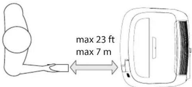
USING THE REMOTE CONTROL
- Point the remote control at the receiver A5 on the air conditioner. The remote control must be no more than 23 ft (7 metres) away from the appliance (without obstacles between the remote control and the receiver).
- The remote control must be handled with care. Do not drop it or expose it to direct sunlight or sources of heat.
Note: The remote control can be safely stored in the appropriate compartment A6 (see figure A page 3).
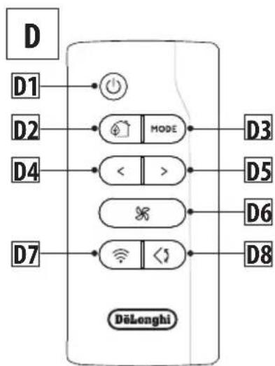
DESCRIPTION OF THE REMOTE CONTROL
flowchart
graph TD
    D[" "] --> D1["●"]
    D1 --> MODE["MODE"]
    D2["○"] --> MODE
    D4["<"] --> MODE
    D4 --> >[>]
    D4 --> <[<]
    D4 --> >[>]
    D7["○"] --> MODE
    D7 --> <[<]
    D7 --> >[>]
    D7 --> WiFi["WiFi"]
    D7 --> <[<]
    D7 --> D8["D8"]
    D3["D3"] --> D5["D5"]
    D6["D6"] --> D6["D6"]
    D8["D8"] --> D8["D8"]
D1. ON/STAND-BY (on/off) button
D2. ECO REAL FEEL button
D3. MODE button
D4. Decrease button
D5. Increase button
D6. Air flow button
D7. WiFi button
D8. Swing button (flap swing)
TURNING THE APPLIANCE ON/OFF
- Plug into the outlet.
- Press the button D1. When turned on, the air conditioner starts operating in the same mode as when it was turned off.
- Press the button again to switch the appliance off.
Note: Never switch the appliance off by removing the plug.
Always switch it off by pushing the button and waiting few minutes before removing the plug. Only in this way the appliance will perform the standard checkings.
The operating modes available on the remote control correspond to those on the appliance control panel C.
SELECTING THE TEMPERATURES
In conditioning modes press button > D5 or < D4 to select the desired temperature.
SELECTING THE AIR FLOW
In conditioning and fan modes, press button ✗D6 to select the desired air flow.
The air flow available are:
(※) Minimum air flow: when maximum silent operation is desired.
(Medium air flow: when the noise level needs to be low but with a good comfort level.
(Maximum air flow: for maximum performance.
The appliance automatically chooses the air flow based on the temperature selected and the environmental conditions. This selection is only available in conditioning mode.

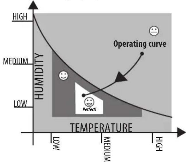
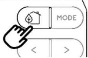
ECO REAL FEEL FUNCTION
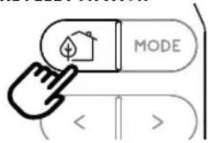
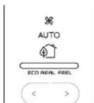
ECO REAL FEEL is the innovative De'Longhi technology that works simultaneously on temperature reduction and humidity control, securing best comfort level. With traditional systems, during working time, optimal comfort conditions may be reached but not secured over time. With ECO REAL
FEEL, once optimal comfort is reached, PAC automatically modulates compressor action and air flow, to keep it over time.
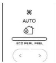
To activate the function, push the button D2 on remote control and the ECO REAL FEEL symbol appears.
After approx. 1 minute, the ECO REAL FEEL indicator C13 switches on and then changes color when approaching the best comfort level (see following diagram).
line
| Temperature | Humidity | | ----------- | -------- | | Low | Medium | | Medium | Low | | High | High | |  |  |
| ORANGE LIGHT GREEN LIGHT BLUE LIGHT | ||
| Room conditions far from optimal level. | Most people feel good room conditions, near optimal level. | Best comfort level. |
- The well-being feeling is a subjective condition: for this reason, different people may judge differently the same environmental conditions.
- In particularly severe environmental conditions (large size of the environment, high temperature or humidity outside, poor insulation of the room, too many of people or strong heat load in the room, strong exposure to the sun ...) this device may not be able to reach the best comfort level.

SWING FUNCTION
The SWING button D8 moves the flap, evenly distributing the air into the room.
When the SWING button is pressed, the flap will begin to move forwards and backwards alternatively.
If pressed again, the flap will be locked into its current position. When the button is next pressed, the flap will start to move forwards and backwards again.
Notes: in order to avoid damaging the internal mechanisms, the flap must not be moved manually.

WIFI FUNCTION
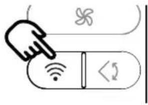
To activate or disactivate the WiFi function, keep touched for few seconds the WiFi button on the remote control till the emission of a double beep.
Once the WiFi icon is displayed it means that the WiFi features are available.
SYMBOL WIFI FIXED

ans that the WiFi features are active AND the "Home WLAN" has been found.
SLOW FLASHING

means that the appliance is searching for the "Home WLAN".
FAST FLASHING

that the "Home WLAN" has not been found or has not been set yet.
"APP CONTROL " ICON

APP CONTROL icon appears it means that the last command has been received via app.
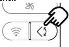
If the memorized "Home WLAN" settings needs to be changed, proceed as follows:
a) keep touched for about 20 seconds the MODE button C2 on the control panel until a prolonged beep is emitted;
b) use the app to enter the new WLAN settings into the unit.
SETTING THE TIMER
Timer programming is an exclusive function of the app: thanks to the many possibilities of timer programming, you can prevent wasting electricity by optimising the operating period, setting delayed start up or shut down of the appliance.
FCC AND CANADA EMC COMPLIANCE INFORMATION
This device complies with Part 15 of the FCC Rules. Operation is subject to the following two conditions:
(1) This device may not cause harmful interference, and
(2) This device must accept any interference received, including interference that may cause undesired operation.
NOTE: This equipment has been tested and found to comply with the limits for a Class B digital device, pursuant to part 15 of the FCC Rules. These limits are designed to provide reasonable protection against harmful interference in a residential installation. This equipment generates, uses and can radiate radio frequency energy and, if not installed and used in accordance with the instructions, may cause harmful interference to radio communications. However, there is no guarantee that interference will not occur in a particular installation. If this equipment does cause harmful interference to radio or television reception, which can be determined by turning the equipment off and on, the user is encouraged to try to correct the interference by one or more of the following measures:
- Reorient or relocate the receiving antenna.
- Increase the separation between the equipment and receiver.
- Connect the equipment into an outlet on a circuit different from that to which the receiver is connected.
- Consult the dealer or an experienced radio/TV technician for help.
Approved under the certification provision of FCC Part 15 as a Class B Digital Device.
Caution: Changes or modifications not expressly approved by the manufacturer could void the user's authority to operate this device.
Caution: To comply with the limits of the Class B digital device, pursuant to Part 15 of the FCC Rules, this device is to comply with Class B limits. All peripherals must be shielded and grounded. Operation with non-certified peripherals
or nonshielded cables my result in interference to radio or reception.
This Class B digital apparatus complies with Canadian ICES-003. CAN ICES-3 (B)/NMB-3(B)
The term "IC:" before the radio certification number only signifies that Industry Canada technical specifications were met.
This device complies with Industry Canada's licence-exempt RSSs. Operation is subject to the following two conditions:
(1) This device may not cause interference; and
(2) This device must accept any interference, including interference that may cause undesired operation of the device.
This equipment complies with FCC and IC radiation exposure limits set forth for an uncontrolled environment. This equipment should be installed and operated with minimum distance 20cm between the radiator and your body. This transmitter must not be co-located or operating in conjunction with any other antenna or transmitter.
This equipment complies with FCC/IC RSS-102 radiation exposure limits set forth for an uncontrolled environment.
This equipment should be installed and operated with minimum distance 20cm between the radiator & your body.
Host device Labeling
This device includes the following module.
Contains FCC ID:
2ANDL3-TYWE1S
Host device Labeling
This device includes the following module.
Contains IC:
23243-TYWE1S
The appliance has a self diagnosis system to identify a number of warning/malfunctions.
Error messages are displayed on the appliance display.
| IF ... IS DISPLAYED, IF | ... IS DISPLAYED, IF ... | IS DISPLAYED, IF ... IS | DISPLAYED, |
 |  | 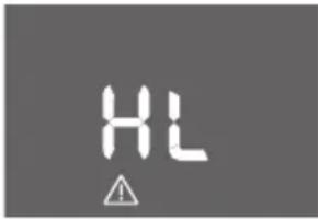 | 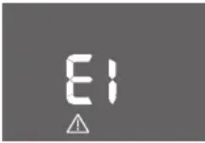 |
| “Low Temperature” (frost prevention) | “Probe Failure” (Probe damaged) | “High Level” (Internal tray full) | “Comunication Failure” (internal communication issue) |
| ..WHAT SHOULD I DO? ..WHAT SHOULD I DO? ..WHAT SHOULD I DO? ..WHAT SHOULD I DO? | |||
| The appliance is fitted with a frost protection device to avoid excessive formation of ice. The appliance starts up again automatically when the defrosting process is completed. | If this is displayed, contact your local authorized service center | Empty the internal safety tank following the instructions in the section “End of season operations” | If this is displayed, contact your local authorized service center. |
TIPS FOR CORRECT USE
To ensure optimal results from your air conditioner, follow these recommendations:
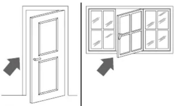
- close the windows and doors in the room to be air conditioned. When installing the air conditioner semi-permanently, you should leave a door slightly open (as little as 0.39 inch. (1 cm)) to guarantee proper ventilation.
natural_image
Diagram showing two door opening scenarios with arrows indicating direction (no text or symbols)Close doors and windows
- Never use the appliance in very damp rooms (laundries for example).
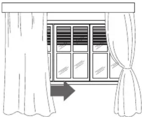
- Protect the room from direct exposure to the sun by partially closing curtains and/or blinds to make the appliance much more economical to run.
natural_image
Line drawing of a window with curtains and a directional arrow (no text or symbols)Close blinds or curtains
- Never use the appliance outdoors.
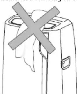
• Make sure there are no heat sources in the room; - make sure the air conditioner is standing on a level surface.
natural_image
Simple line drawing of a device with a cross mark symbol (no text or labels)do not cover the appliance
- Never rest objects of any kind on the air conditioner;
- Never obstruct the air intake or outlet grilles;
CLEANING
Beforecleaningormaintenance,turntheapplianceoffby touching the button, wait a few seconds, then unplug from the outlet.
CLEANING THE CABINET
You should clean the appliance with a slightly damp cloth then dry with a dry cloth. For safety reasons, never wash the air conditioner with water.
Precautions
Never use petrol, alcohol or solvents to clean the appliance. Never spray insecticide liquids or similar.
CLEANING THE AIR FILTER
If the filter is dirty, air circulation is compromised and the efficiency of the appliance decreases.
It is therefore good practice to clean the filter at regular intervals. The frequency depends on the duration and conditions of operation.
If the unit is used constantly or systematically, you are recommended to clean the filter once a week.
The filter is housed in the intake grille.
To clean the filter, extract as shown in fig. 8.
To maintain the efficiency of the air conditioner, it is recommended to clean the dust filter after every week of use.
The filter is located near the intake grille. Remove the grille to access the filter. To clean the filter, it will need to be extracted as shown in fig. 8.
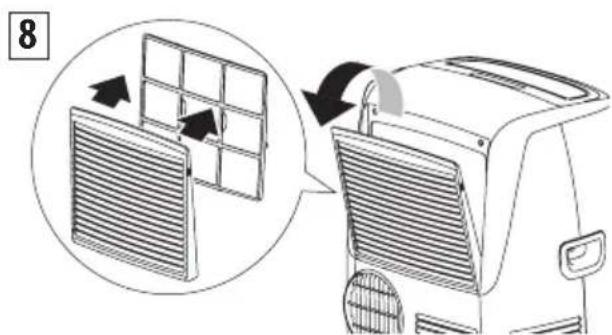
Use a vacuum cleaner to remove any dust deposited on the filter. If it is very dirty, submerge it into warm water and rinse it several times. The water temperature must be kept below 104^ F ( 40^ C). After washing the filter, allow it to dry.
Afterwashingthefilter, allowittodrycompletely before repositioning it.
CHECKS AT THE START OF THE SEASON
Make sure the power cable and socket are in perfect condition and make sure the earthing system is efficient. Comply strictly with the installation standards.
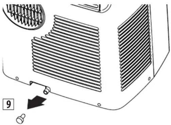
END OF SEASON OPERATIONS
To drain all water from the circuit, remove the cap A11 from the drainage on the back of the appliance and allow the water to drain out into a basin (fig. 9).
To facilitate this operation, at the start of the season, it's possible to apply the water drain hose with cap B6.
In order to properly storage the appliance at the end of the season, we suggest you cover it with the supplied end of season dust cover B8 and you put the accessories in the relevant end of season accessories bag B9.
natural_image
Technical diagram of a heat exchanger or radiator component with cooling fins and a numbered arrow indicating assembly (no text or symbols present)When the appliance is empty, replace the cap.
Clean the filter and dry thoroughly before putting back.
TECHNICAL SPECIFICATIONS
Power supply voltage see rating label
Max. absorbed power during air conditioning
Refrigerant "
Cooling capacity "
LIMIT CONDITIONS
Room temperature for
air conditioning 64 ÷ 95^ ( 18^ ÷ 35^ )
Room temperature for
heating 50 ÷ 77°F (10 ÷ 25°C)
Transport, filling, cleaning, recovery and disposal of refrigerant should be performed by a technical service centre appointed by the manufacturer only.
The appliance should be disposed of by a specialist centre appointed by the manufacturer only.
TO AVOID DAMAGE TO THE UNIT:
NEVER TRANSPORT OR TURN THE APPLIANCE UPSIDE DOWN OR ON ITS SIDE. IF THIS OCCURS, WAIT 6 HOURS BEFORE TURNING THE APPLIANCE ON, 24 HOURS IS RECOMMENDED. After the unit has been on its side, oil needs to return to the compressor to ensure proper function. Without allowing the unit this time (6-24 hours) the unit may function for only a short time, and then the compressor will break down from lack of oil.
ELECTRICAL CONNECTION
This appliance is equipped with a 3 prong grounded plug. The plug must be connected into an outlet that is properly installed and grounded in the accordance with all local codes and ordinances. Do not modify the plug provided with the appliance. If it will not fit the outlet, have a proper outlet installed by a qualified electrician or relocate the unit to a proper outlet. If the household electrical supply does not meet the above specifications, or if you are not sure your home has an effective electrical ground, have a qualified electrician or your local electrical utility company check it and correct any problems.
SAFETY PLUG
The appliance is fitted with a safety plug to protect the power cable. If power is cut off, unplug from the outlet and make sure the power cable is undamaged. If the cable is damaged, call the service center immediately. If power cuts off frequently and the power cable is undamaged, contact a qualified electrician.
If the safety device incorporated in the plug trips and cuts off the power supply, check that the power cable and plug are not damaged. If the power cable is undamaged, to restore operation press the "RESET" button. To verify correct operation of the plug, press the "TEST" button periodically and make sure the appliance disconnects. If this is not the case, contact the service center. To restore operation, press the "RESET" button.
TROUBLESHOOTING
Check the following points before calling the authorised Technical Service Centre in your area.
| PROBLEMS CAUSES SOLUTIONS | ||
| The air conditioner does not turn on It is not | plugged in plug it in | |
| there is no power wait | ||
| the internal protection device was triggered | call the help centre | |
| The air conditioner works for a short period of time | the air exhaust hose is obstructed or bent | correctly position the air exhaust hose, limiting the length and curves as much as possible and avoiding any obstructions |
| an obstruction is impeding air exhaust outside | identify and remove the obstacles that impede air exhaust outside | |
| The air conditioner runs but does not cool the room | windows, doors, drapes open close the window | windows, doors and drapes, keeping in mind the “recommendations for proper use” |
| there is some heat source in the room (oven, hair dryer, etc.) | eliminate the heat source | |
| the air exhaust hose is disconnected from the appliance | attach the air exhaust hose to the housing on the back of the appliance (fig.1) | |
| dust filters clogged clean or replace the filter | filters as previously described | |
| the technical characteristics of the appliance are not suitable for cooling the room where it is located | ||
| During operation there is an unpleasant odour in the room | dust filters clogged clean or replace the filter | filters as previously described |
| The air conditioner does not work for about 3 minutes from restart | to protect the compressor there is an internal device that delays startup for about 3 minutes from restart | wait |
| The display shows the symbol with one of the following messages: HL/PF/FI | the appliance has a self-diagnosis system that identifies some operating errors | refer to the SELF-DIAGNOSIS chapter |
Précautions importantes
natural_image
Technical illustration of a turbocharger assembly showing airflow path and component details (no text or symbols)natural_image
Line drawing of a small air conditioner unit connected to a wall-mounted air conditioner unit (no text or symbols)natural_image
Line drawing of a small air conditioner unit connected to a window with a hose, no text or symbols presentnatural_image
Line drawing of a hairless vacuum cleaner with coiled hose and control panel (no text or symbols)In conditioning modes press button > D5 or < D4 to select the desired temperature.
SELECTING THE AIR FLOW
In conditioning and fan modes, press button ⚠6 to select the desired air flow.
The air flow available are:
(8)
Minimum air flow: when maximum silent operation is desired.
(Medium air flow: when the noise level needs to be low but with a good comfort level.
(Maximum air flow: for maximum performance.
The appliance automatically chooses the air flow
AUTO
based on the temperature selected and the environmental conditions. This selection is only available in conditioning mode.

FONCTION SENSATION RÉELLE (ECO REAL FEEL)
This device complies with Part 15 of the FCC Rules. Operation is subject to the following two conditions:
(1) This device may not cause harmful interference, and
(2) This device must accept any interference received, including interference that may cause undesired operation.
NOTE: This equipment has been tested and found to comply with the limits for a Class B digital device, pursuant to part 15 of the FCC Rules. These limits are designed to provide reasonable protection against harmful interference in a residential installation. This equipment generates, uses and can radiate radio frequency energy and, if not installed and used in accordance with the instructions, may cause harmful interference to radio communications. However, there is no guarantee that interference will not occur in a particular installation. If this equipment does cause harmful interference to radio or television reception, which can be determined by turning the equipment off and on, the user is encouraged to try to correct the interference by one or more of the following measures:
- Reorient or relocate the receiving antenna.
- Increase the separation between the equipment and receiver.
- Connect the equipment into an outlet on a circuit different from that to which the receiver is connected.
- Consult the dealer or an experienced radio/TV technician for help.
Approved under the certification provision of FCC Part 15 as a Class B Digital Device.
Caution: Changes or modifications not expressly approved by the manufacturer could void the user's authority to operate this device.
Caution: To comply with the limits of the Class B digital device, pursuant to Part 15 of the FCC Rules, this device is to comply with Class B limits. All peripherals must be shielded and grounded. Operation with non-certified peripherals or nonshielded cables my result in interference to radio or reception.
This Class B digital apparatus complies with Canadian ICES-003. CAN ICES-3 (B)/NMB-3(B)
The term "IC:" before the radio certification number only signifies that Industry Canada technical specifications were met.
This device complies with Industry Canada's licence-exempt
RSSs. Operation is subject to the following two conditions:
(1) This device may not cause interference; and
(2) This device must accept any interference, including interference that may cause undesired operation of the device.
This equipment complies with FCC and IC radiation exposure limits set forth for an uncontrolled environment. This equipment
should be installed and operated with minimum distance 20cm between the radiator and your body. This transmitter must not be co-located or operating in conjunction with any other antenna or transmitter.
This equipment complies with FCC/IC RSS-102 radiation exposure limits set forth for an uncontrolled environment.
This equipment should be installed and operated with minimum distance 20cm between the radiator & your body.
Host device Labeling
This device includes the following module.
Contains FCC ID:
2ANDL3-TYWE1S
Host device Labeling
This device includes the following module.
Contains IC:
2ANDL3-TYWE1S
AUTODIAGNOSTIC
natural_image
Diagram showing two door opening scenarios with arrows indicating direction (no text or symbols)natural_image
Line drawing of a window with curtains and a double-headed arrow pointing to the left pan (no text or symbols)natural_image
Simple line drawing of a device with a cross mark on top, no text or symbols presentNe pas couvrir
natural_image
Technical diagram of a car air conditioning unit showing heat exchangers and cooling fins (no text or symbols)natural_image
Technical illustration of a turbocharger assembly showing airflow direction and component details (no text or symbols)natural_image
Line drawing of a small air conditioner unit with a hose inserted, placed in a room with a window and grid panel (no text or symbols)natural_image
Line drawing of a small air conditioner unit connected to a window with a hose, no text or symbols presentnatural_image
Line drawing of a hairless vacuum cleaner with a coiled hose, no text or symbols present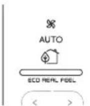
 |  |  |
| ORANGE LIGHT GREEN LIGHT BLUE LIGHT | ||
| Room conditions far from optimal level. | Most people feel good room conditions, near optimal level. | Mejor nivel de confort. |
This device complies with Part 15 of the FCC Rules. Operation is subject to the following two conditions:
(1) This device may not cause harmful interference, and
(2) This device must accept any interference received, including interference that may cause undesired operation.
NOTE: This equipment has been tested and found to comply with the limits for a Class B digital device, pursuant to part 15 of the FCC Rules. These limits are designed to provide reasonable protection against harmful interference in a residential installation. This equipment generates, uses and can radiate radio frequency energy and, if not installed and used in accordance with the instructions, may cause harmful interference to radio communications. However, there is no guarantee that interference will not occur in a particular installation. If this equipment does cause harmful interference to radio or television reception, which can
be determined by turning the equipment off and on, the user is encouraged to try to correct the interference by one or more of the following measures:
- Reorient or relocate the receiving antenna.
- Increase the separation between the equipment and receiver.
- Connect the equipment into an outlet on a circuit different from that to which the receiver is connected.
- Consult the dealer or an experienced radio/TV technician for help.
Approved under the certification provision of FCC Part 15 as a Class B Digital Device.
Caution: Changes or modifications not expressly approved by the manufacturer could void the user's authority to operate this device.
Caution: To comply with the limits of the Class B digital device, pursuant to Part 15 of the FCC Rules, this device is to comply with Class B limits. All peripherals must be shielded and grounded. Operation with non-certified peripherals or nonshielded cables my result in interference to radio or reception.
This Class B digital apparatus complies with Canadian ICES-003. CAN ICES-3 (B)/NMB-3(B)
The term "IC:" before the radio certification number only signifies that Industry Canada technical specifications were met.
This equipment complies with FCC and IC radiation exposure limits set forth for an uncontrolled environment. This equipment should be installed and operated with minimum distance 20cm between the radiator and your body. This transmitter must not be co-located or operating in conjunction with any other antenna or transmitter.
This equipment complies with FCC/IC RSS-102 radiation exposure limits set forth for an uncontrolled environment.
This equipment should be installed and operated with minimum distance 20cm between the radiator & your body.
Host device Labeling
This device includes the following module.
Contains FCC ID:
2ANDL3-TYWE1S
Host device Labeling
This device includes the following module.
Contains IC:
23243-TYWE1S
AUTODIAGNÓSTICO
natural_image
Diagram showing two door opening scenarios with arrows indicating direction (no text or symbols)natural_image
Line drawing of a window with curtains and a directional arrow (no text or symbols)natural_image
Simple line drawing of a device with a cross mark symbol (no text or labels)No cubra
natural_image
Technical diagram of a heat exchanger or radiator component with cooling fins and mounting holes (no text or symbols)
- CONDITIONNEUR D'AIR PORTATIF
- Important safeguard
- Specific warnings for appliances with R410A refrigerant gas
- ENVIRONMENTAL INFORMATION:
- Save these instructions
- This product is for household only
- INTRODUCTION
- DESCRIPTION
- Description of accessories (See page 3 - B)
- Electrical connection
- USE
- CONDITIONING WITH INSTALLATION
- Note:
- CONDITIONING WITHOUT INSTALLATION
- You can also set-up in a double-hung window:
- Other set-up methods:
- DESCRIPTION OF THE CONTROL PANEL (C)
- TURNING THE APPLIANCE ON/OFF
- Before plugging the appliance
- MODES SELECTION
- WiFi FUNCTION
- \* AIR CONDITIONING MODE
- DEHUMIDIFYING MODE
- FAN MODE
- SELECT THE TEMPERATURE SCALE
- USING THE REMOTE CONTROL
- DESCRIPTION OF THE REMOTE CONTROL
- SELECTING THE TEMPERATURES
- SELECTING THE AIR FLOW
- SYMBOL WIFI FIXED
- SLOW FLASHING
- FAST FLASHING
- "APP CONTROL " ICON
- SETTING THE TIMER
- FCC AND CANADA EMC COMPLIANCE INFORMATION
- Host device Labeling
- 2ANDL3-TYWE1S
- 23243-TYWE1S
- TIPS FOR CORRECT USE
- CLEANING
- CLEANING THE CABINET
- Precautions
- CLEANING THE AIR FILTER
- CHECKS AT THE START OF THE SEASON
- END OF SEASON OPERATIONS
- TECHNICAL SPECIFICATIONS
- LIMIT CONDITIONS
- TO AVOID DAMAGE TO THE UNIT:
- SAFETY PLUG
- TROUBLESHOOTING
- Précautions importantes
- AUTODIAGNOSTIC
- AUTODIAGNÓSTICO
- No cubra
Brand : DELONGHI
Model : Pinguino Smart PACEL140LRFK-3ALBK
Category : Air Conditioning