
CMXGZBF71243311 - Seed spreader Craftsman - Free user manual and instructions
Find the device manual for free CMXGZBF71243311 Craftsman in PDF.

| Product Type | Combined Seed Spreader and Lawn Aerator (tow-behind) |
| Brand | Craftsman |
| Model | CMXGZBF71243311 |
| Hopper Capacity | Approximately 22.7 kg (50 lb) |
| Dimensions (approx.) | 91 x 61 x 61 cm (36 x 24 x 24 in) |
| Weight (approx.) | 18 kg (40 lb) |
| Power Source | Manual (towed by a vehicle) |
| Maximum Towing Speed | 16 km/h (10 mph) |
| Main Functions | Spreading seeds, fertilizer, and chemicals; lawn aeration (aerator spikes) |
| Flow Adjustment | Knob with wing nut, adjustable range according to material |
| Working Width (approx.) | Approximately 46 cm (18 in) for spreading |
| Hopper Material | Painted steel |
| Wheels | 2 solid plastic wheels with tires |
| Hitch | Hitch tube with pin, compatible with garden tractors |
| Maintenance | Empty and clean after each use; oil metal parts; lubricate chain and bearings once a year |
| Safety | Wear eye and hand protection when handling chemicals; do not allow riders; read chemical label; max speed 16 km/h |
| Warranty | Limited 3-year warranty (1 year for material and workmanship defects) |
| Customer Service | 1-888-331-4569 (United States and Canada) |
| Spare Parts | Available through manufacturer (Agri-Fab, Inc.) or customer service |
| Repairability | User-serviceable (bolts, wheels, chain, bearings); warranty repair possible |
| Certifications | Trademark of Stanley Black & Decker, Inc. |
| User Manual | Available as free PDF at notice-facile.com |
Frequently Asked Questions - CMXGZBF71243311 Craftsman
User questions about CMXGZBF71243311 Craftsman
0 question about this device. Answer the ones you know or ask your own.
Ask a new question about this device
Download the instructions for your Seed spreader in PDF format for free! Find your manual CMXGZBF71243311 - Craftsman and take your electronic device back in hand. On this page are published all the documents necessary for the use of your device. CMXGZBF71243311 by Craftsman.
USER MANUAL CMXGZBF71243311 Craftsman
English (original instructions) 1
Definitions: Safety Alert Symbols and Words
This instruction manual uses the following safety alert symbols and words to alert you to hazardous situations and your risk of personal injury or property damage.
DANGER: Indicates an imminently hazardous situation which, if not avoided, will result in death or serious injury.
WIPING: Indicates a potentially hazardous situation which, if not avoided, could result in death or serious injury.
CAITION: Indicates a potentially hazardous situation which, if not avoided, may result in minor or moderate injury.
(Used without word) Indicates a safety related message.
NOTICE: Indicates a practice not related to personal injury which, if not avoided, may result in property damage.
SAFETYWARNINGS
WARNING: Read all safety warnings, illustrations, illustrations and specifications provided with this tool. Failure to follow all instructions listed below may result in fire and/or serious injury.
SAVE ALL WARNING AND INSTRUCTIONS FOR FUTURE REFERENCE
SafetyWarnings
a) Read this owner's manual before attempting to assemble or operate the spiker/spreader.
b) Read the towing vehicle owner's manual and know how to operate the tractor before using the spiker/spreader attachment.
c) Do not allow anyone to ride on or sit on the spiker/spreader.
d) Never allow children to operate the tractor or spiker/spreader attachment.
e) Do not allow adults to operate the tractor or spiker/spreader without proper instructions.
f) Read the chemical label for instructions and cautions for handling and applying chemicals.
g) Wear eye and hand protection when handling and using lawn chemicals.
h) Always begin with the transmission in first (low) gear and gradually increase speed as conditions permit. Maximum towing speed - 10 M.P.H.
i) Do not drive too close to a creek or ditch and be alert for holes and other hazards which could
cause you to lose control of the tractor and spiker/spreader.
j) Before operating the vehicle on any grade (hill) refer to the safety rules in the vehicle owner's manual concerning safe operation on slopes. Stay off steep slopes!
k) Follow maintenance and lubrication instructions as outlined in this manual.
WARNING: Read all safety warnings and all
Inductions. Failure to follow the warnings and instructions may result in damage or serious injury.
WARNING: Never modify the product or any part of it. Age or personal injury could result.

WARNING: To reduce the risk of injury, read the instruction manual.
If you have any questions or comments about this or any product, call CRAFTSMAN toll free at: 1-888-331-4569.
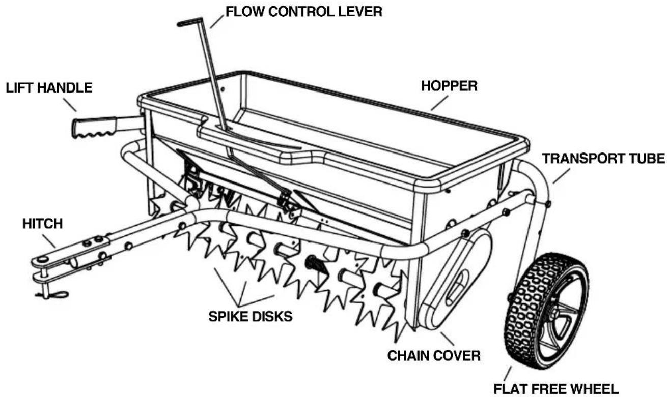
ASSEMBLED PRODUCT DIAGRAM
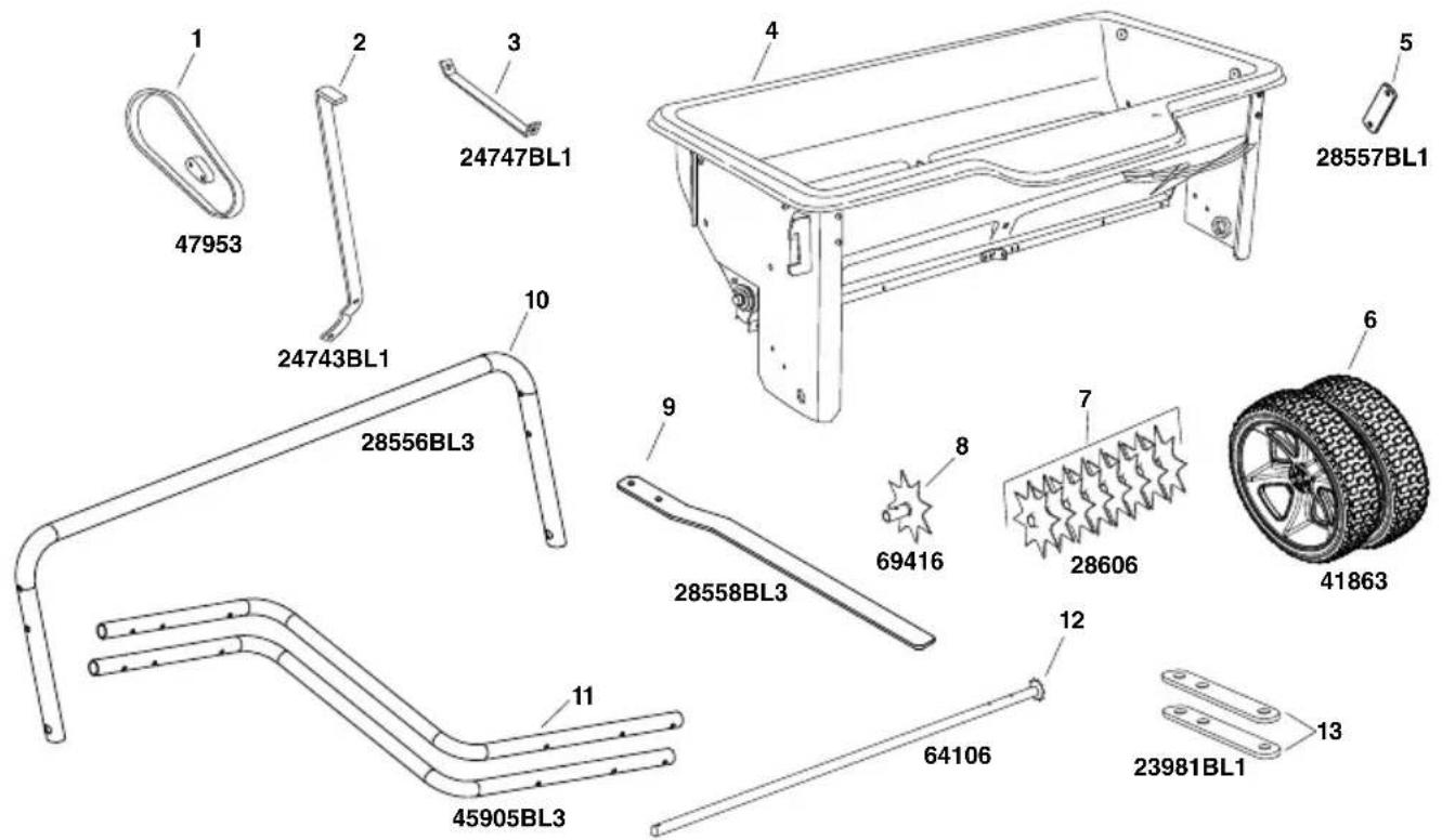
CARTON CONTENTS
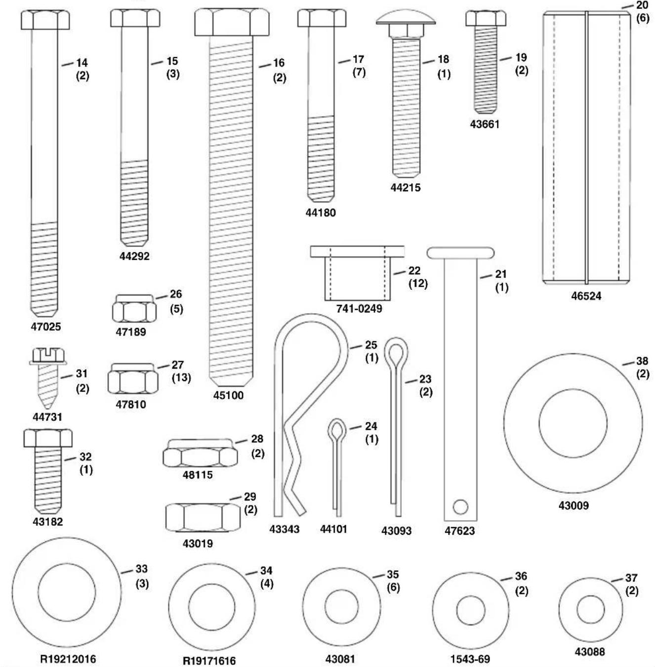
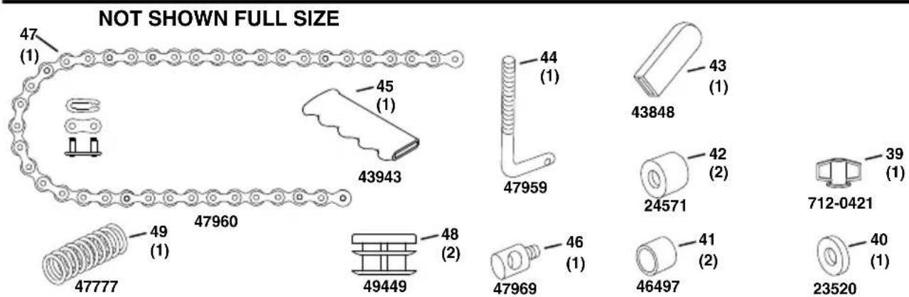
HArDWAre PACKAGE COntentS
ASSEMBLY
Tools you will need
(2) 7/16" Wrenches
(2) 1 / 2 Wrenches
(2) 3 / 4'' or Adjustable Wrenches
(1) Screwdriver
(1) Pliers
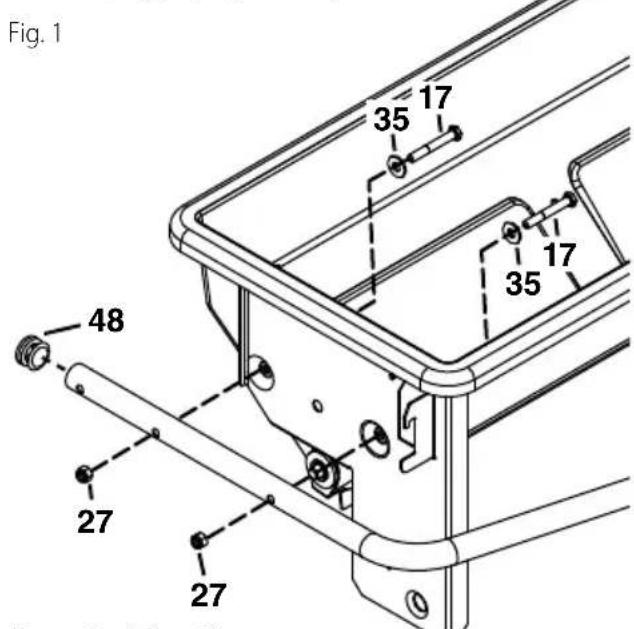
Step 1: (Fig. 1)
- Attach a hitch tube to the right hand side of the hopper using two 5 / 16'' x 2-1/4" hex bolts (17), 5 / 16'' flat washers (35) and 5 / 16'' nylock hex nuts (27). Assemble the bolts and washers from inside the hopper. Insert a tube plug (48). Tighten. Repeat for the other side.
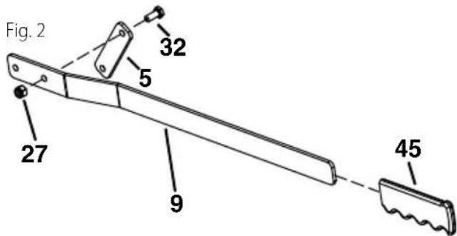
Step 2: (Fig. 2)
- On the right side, assemble the handle brace bracket (5) to the lift handle (9) using a 5 / 16'' × 3 / 4'' hex bolt (32) and 5 / 16'' nylock nut (27). Tighten. See figure 2.
- Assemble the grip (45) onto the lift handle.
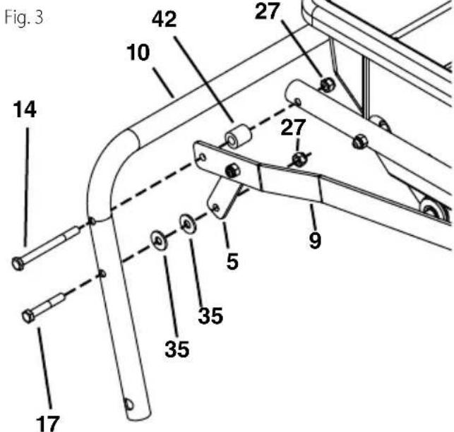
Step 3: (Fig. 3)
- Insert a 5/16" x 3-1/2" hex bolt (14) through the transport tube (10), the lift handle (9), a spacer (42), and through the hitch tube. Secure with a 5/16 nylock nut (27).
- Insert a 5 / 16'' x 2'' hex bolt (17) through the transport tube (10), two 5 / 16'' flat washers (35), and the handle brace bracket. Secure with a 5 / 16'' nylock nut (27). Tighten. See figure 3.
Step 4: (Fig. 4)
- On the left side, insert a 5/16'' × 3 - 1/2'' hex bolt (14) through the upper hole on the transport tube (10), a spacer (42), and the hitch tube. Secure with a 5/16 nylock nut (27). Do not tighten yet. See figure 4.
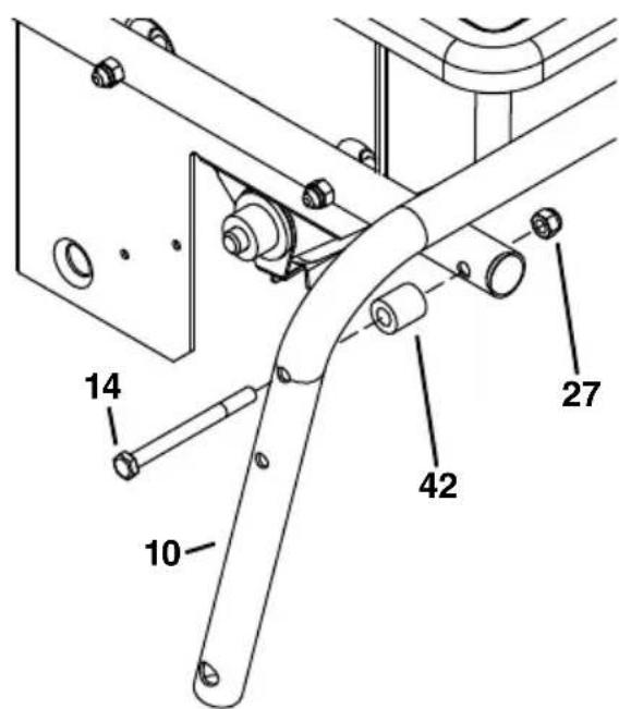
Fig. 4
ENglISh
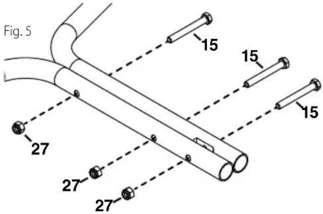
Step 5: (fig. 5)
- Fasten the hitch tubes together using three 5/16"x 2-1/2" hex bolts (15) and 5/16" nylock hex nuts (27). Do not tighten yet. See figure 5.
Step 6: (fig. 6)
- Attach the hitch brackets (13) to the hitch tubes using two 5 / 16'' × 2'' hex bolts (17) and 5 / 16'' nylock hex nuts (27). Do not tighten yet. See figure 6.
- Install the hitch pin (21) through the hitch brackets (13), and secure with a 3/32 hair cotter pin (25).
- Tighten all loose bolts and nuts that have been assembled.
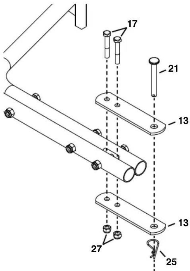
Fig.6
Step 7: (fig. 7)
- Assemble a 1/2'' × 4'' hex bolt (16), a .531 washer (34), a wheel (6), a .531 washer (34), and a .5" jam nut (29). Finger tighten only.
- Attach the wheel assembly to the transport tube using a 1/2" nylock jam nut (28). Repeat for the other side. See figure 7.
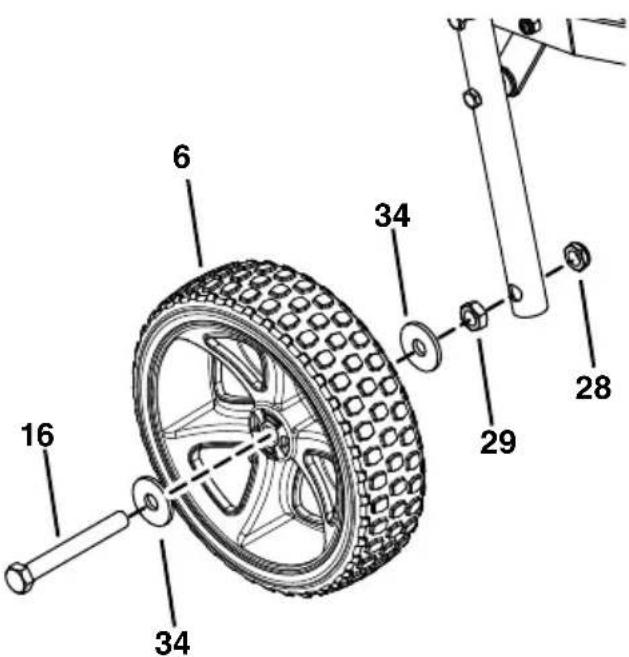
Fig. 7
Step 8: (fig. 8)
- Screw a 1/4" nylock hex nut (26) all the way onto the flow control link (44). Assemble the ferrule (46) onto the link and then start a 1/4" nylock hex nut one or two turns onto the link. See figure 8.
- Assemble the ferrule (46) into the hole at the end of the flow control lever (2) using a 1/4'' nylock hex nut (26). Tighten the nut, leaving it loose enough that the ferrule can pivot. See figure 8.
- Assemble the grip (43) onto the end of the flow control lever. See figure 8.
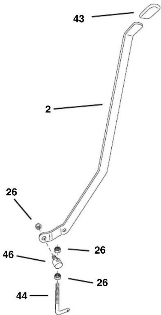
Fig. 8
Step 9: (fig. 9)
- Place the flow control lever into the slot in the hopper. See figure 9.
- Place the center brace (3) into the hopper. Insert a 1/4'' x 1" hex bolt (19) through the center brace and the front of the hopper. Assemble a nylon washer (36), the flow control lever and a 1/4'' nylock hex nut (26) onto the bolt. Do not tighten yet. See figure 9.
- Insert the other 1 / 4'' x 1" hex bolt (19) through the center brace and the rear of the hopper. Assemble a 1 / 4'' flat washer (37) and 1 / 4'' nylock hex nut (26) onto the bolt. Tighten both the front and rear bolts. See figure 9.
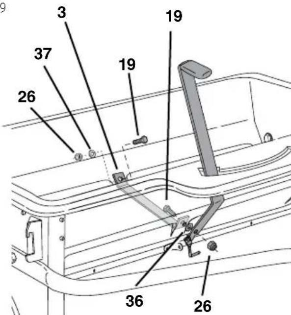
Fig. 9
Step 10: (fig. 10)
- Insert the 5 / 16'' × 1 - 3 / 4'' carriage bolt (18) up through the slot and secure it with a nylon washer (36) and the plastic wing nut (39). See figure 10.
- Move the lift handle into the locked position as shown in figure 10 and then tip the spreader back to rest on the wheels and the rear of the hopper.
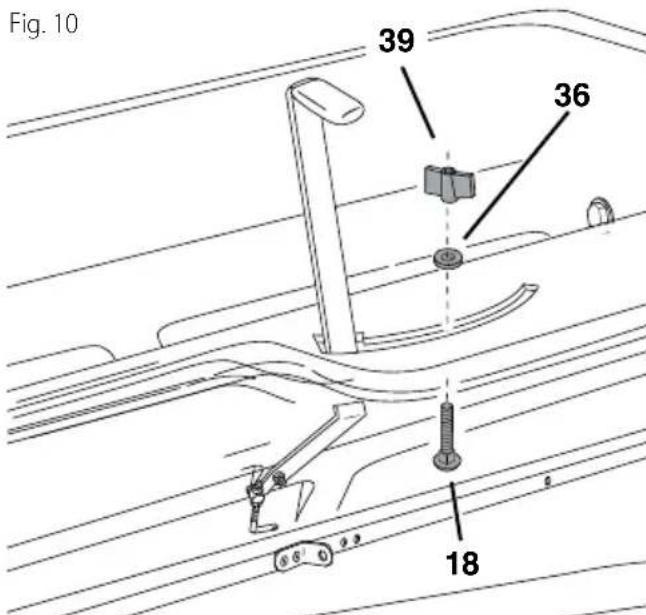
Fig. 10
ENglISh
Step 11: (fig. 11)
Move the flow control lever (2) as far as it will go to the "OFF" position. Push the feed plate back as far as it will go to the closed position. See figure 11.
Place the bent end of the flow control link (44) into the feed plate bracket and a 1/4'' flat washer (37). Secure it with a 3/32'' × 3/4'' cotter pin (24). See figure 11.
Tighten the lower 1/4 nylock hex nut (26) until it touches the bottom of the ferrule, then tighten the upper 1/4 nylock hex nut (26) until it is snug against the top of the ferrule. See figure 11.
Open and close the feed plate using the flow control lever. Check to make sure the feed plate is closed completely when the lever is in the "OFF" position. If the feed plate does not close completely, adjust the 1/4" nylock hex nuts (26) on the flow control link (44). See figure 11.
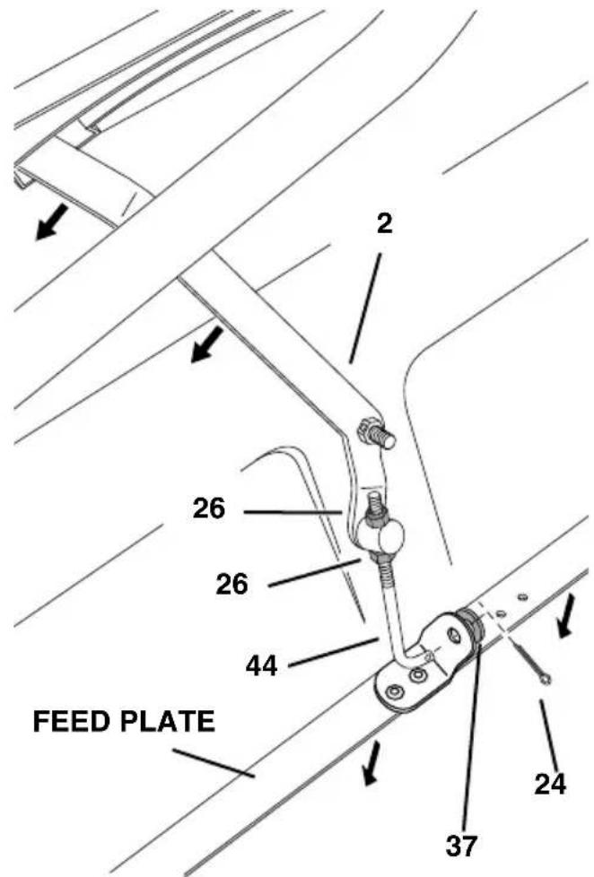
Fig. 11
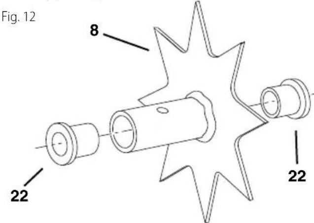
Step 12: (fig. 12)
- Push a flanged bearing (22) into each side of the drive disk (8). See figure 12.
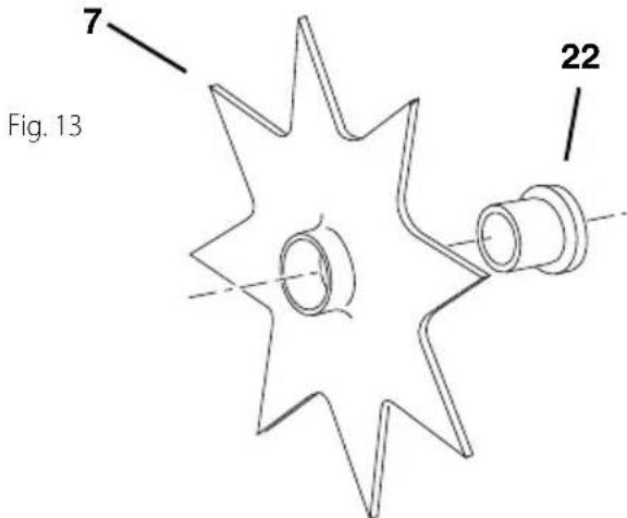
Step 13: (fig. 13)
- Push a flanged bearing (22) into each of the eight spiked disks (7), from the side shown in figure 13.
Step 14: (fig. 14)
- Press flanged bearings (22) into both of the end plates. See figure 14.
- Place the 1/4" thick spacer (40) onto the spike disk shaft (12) and then insert the shaft through the flanged bearing (22) in the left hand end plate. See figure 14.
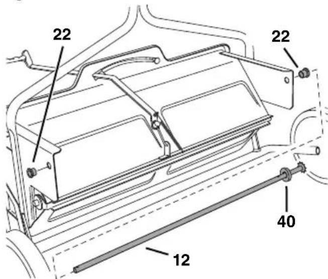
Fig. 14
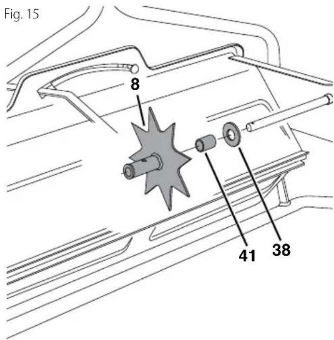
Step 15: (fig. 15)
- Place a large washer (38), short spacer tube (41), and the drive disk (8) onto the shaft. Fit the short spacer tube and large washer onto the flanged bearing in the end plate. See figure 15.
Step 16: (fig. 16)
- Place two spike disks (7), separated by a long spacer tube (20), onto the shaft. Fit the long spacer tube onto the ends of the flanged bearings in the disks. See figure 16.
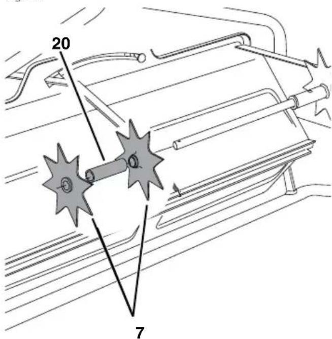
Fig. 16
Step 17: (fig. 17)
- Place a 5/8" flat washer (33), the compression spring (49) and another 5/8" flat washer (33) onto the shaft. See figure 17.
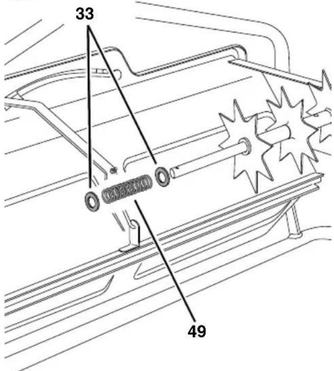
Fig. 17
Step 18: (fig. 18)
- Place two spike disks (7), separated by a long spacer tube (20), onto the shaft. Fit the long spacer tube onto the ends of the flanged bearings in the disks. See figure 18.
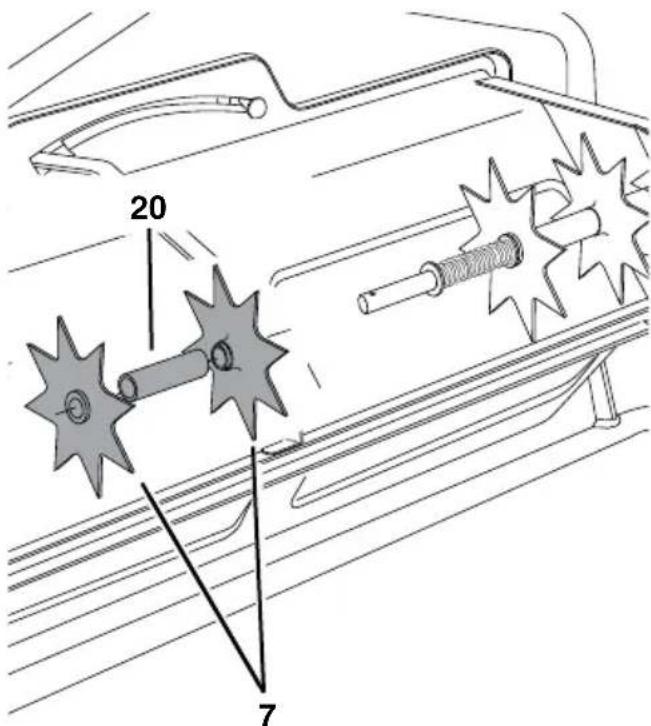
Fig. 18
ENglISh
Step 19: (fig. 19)
- Place a long spacer tube (20) onto the shaft. See figure 19.
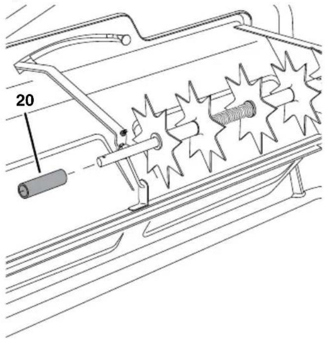
Fig. 19
Step 20: (fig. 20)
- Place two spike disks (7), separated by a long spacer tube (20), onto the shaft. Fit the long spacer tube onto the ends of the flanged bearings in the disks. See figure 20.
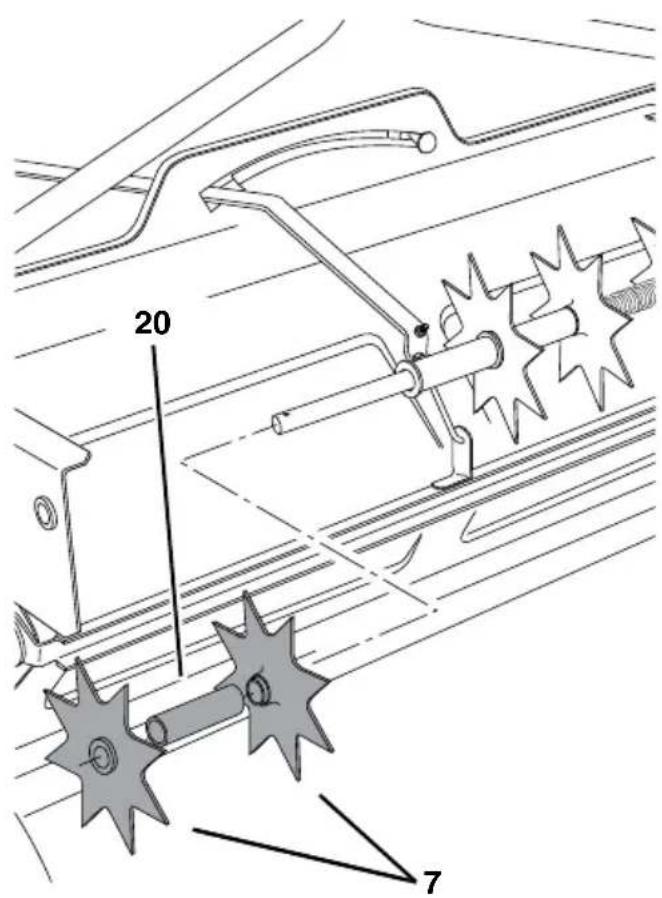
Fig. 20
Step 21: (fig. 21)
- Place a long spacer tube (20) onto the shaft.
- Place two spike disks (7), separated by a long spacer tube (20), onto the shaft. Fit the long spacer tube onto the ends of the flanged bearings in the disks. See figure 21.
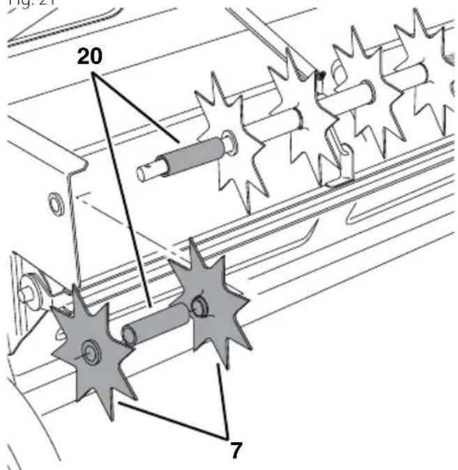
Fig. 21
Step 22: (fig. 22)
- Place a short spacer tube (41) and then a large washer (38) onto the shaft. Fit the short spacer tube and washer onto the end of the flanged bearing in the end plate. Push the shaft on through the flanged bearing in the end plate. See figure 22.
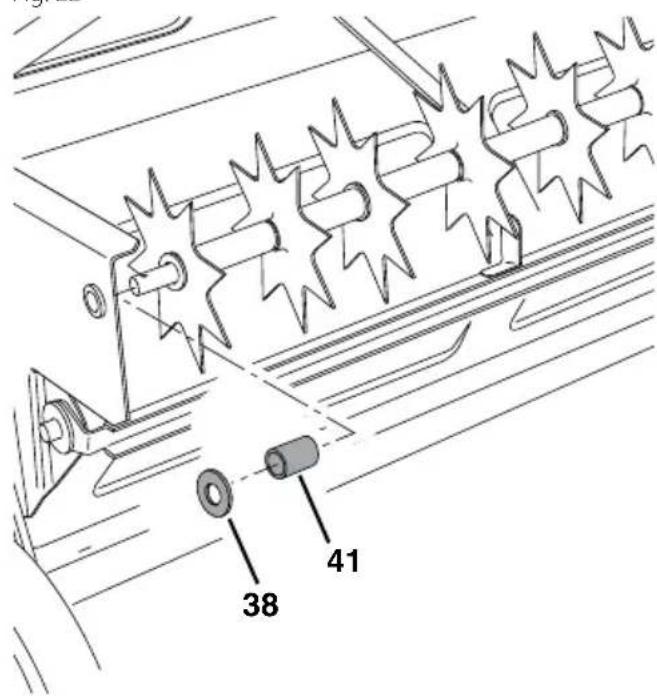
Fig. 22
Step 23: (fig. 23)
-
Place a 5/8" flat washer (33) onto the end of the spike disk shaft and secure the shaft with a 1/8'' × 1-1/2'' cotter pin (23) by spreading the ends of the cotter pin. See figure 23.
-
Fasten the drive disk to the shaft using a 1/8'' × 1-1/2'' cotter pin (23) by spreading the ends of the cotter pin. See figure 23.
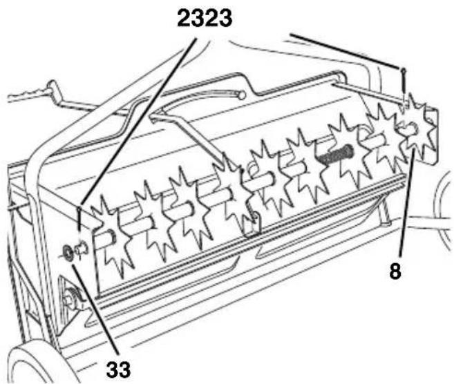
Fig. 23
Step 24: (fig. 24)
-
Remove connecting link from chain and assemble the chain (47) onto the two sprockets on the left side of the hopper. Fasten the ends of the chain together using the connecting link. See figure 24.
-
Place the chain cover over the chain and fasten it to the hopper end plate using two self tapping screws (31). See figure 24.
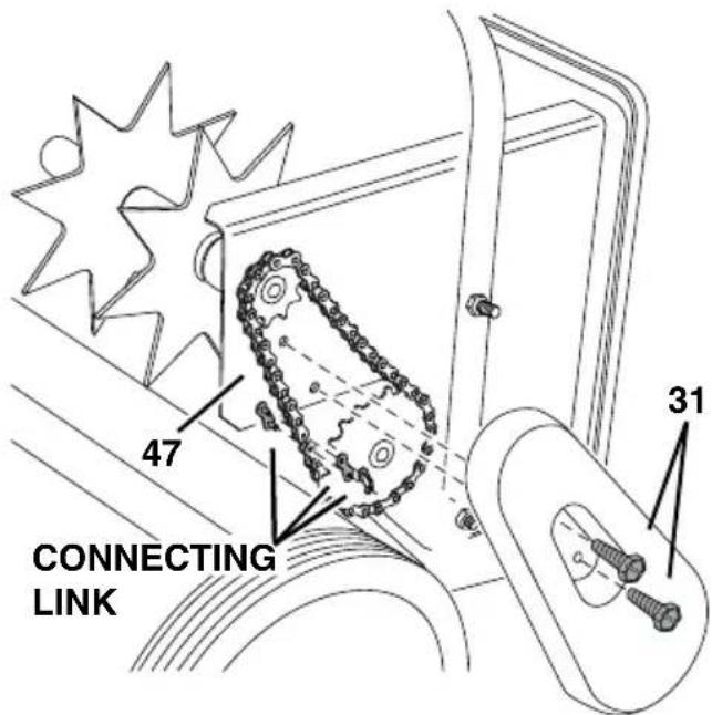
Fig. 24
OPerAtiOn
HOW tO uSe YOur SPIKer/SPreader
Refer to the instruction label on the material package and to the instruction decal on your spreader to help determine the proper spreader setting and application rate. Also see the Setting Chart on this page for a general range of settings for commonly used materials.
- Determine the approximate square footage of the area to be covered and estimate the amount of fertilizer or seed required.
- Move the spreader to the area where application is to begin.
- Loosen the plastic wing nut and move it to the desired setting. Retighten the nut. See figure 25.
Make sure the flow control lever is in the "OFF" position. Fill the hopper, and break up any lumps.
Lower the aerator spikes to the operating position.
- Start the spreader in motion and then move the flow control lever to the "ON" position (against the plastic wing nut) as you travel across your lawn. The maximum towing speed is 3 m.p.h.
- Do not make sharp turns with spikes in the ground.
- Raise aerator spikes to transport position when crossing over concrete or other hard surfaces.
- Do not aerate if the ground is extremely hard or dry. If ground is too dry, sprinkle or water for one to two hours prior to use.
- Do not aerate if the ground is too wet.
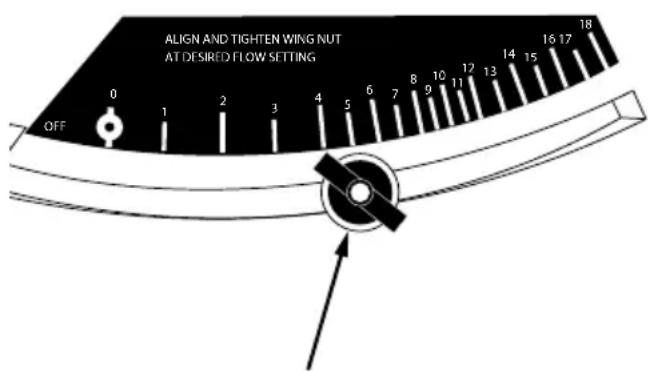
Fig. 25
WING NUT SHOWN AT FLOW SETTING "5"
Flow Rate Setting
MATERIAL TYPE At 3 M.P.H.
Fertilizer Granular / Pelleted 0-1/0-2
Grass Seed Fine / Coarse 5-6/7-8
3 M.P.H. is equivalent to traveling 100 feet in 23 seconds.
aPLicatiOn tiPS
- To help prevent granular material from compacting and clogging the hopper, avoid unnecessary towing when the hopper flow plates are closed.
- Reduce the flow setting for speeds slower than
3 M.P.H.
- To avoid misses or striping, overlap the previous wheel tracks by approximately 5^ to 6^ .
- For easiest application, first apply material across both ends of the area. Two or three passes on each end are sufficient. Then apply material back and forth as shown. Use the end areas for turning around, shutting off the spreader as you enter the end areas and turning the spreader on again as your leave the end areas for your next pass. See figure 26.
- If lawn is odd shaped, spread a border around the edges and then spread between the border.
- Be careful when spreading around ornamental plants because weed control chemicals can damage these plants.
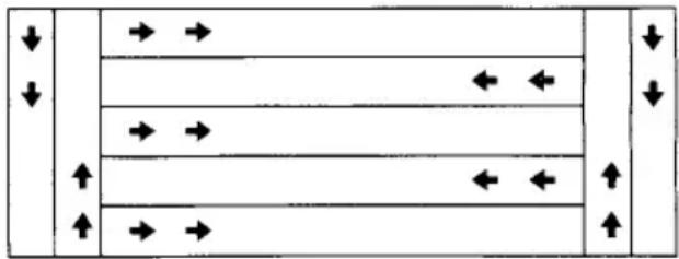
Fig. 26
CAutloN: Spike points are sharp. Exercise caution handling or working near spike disks.
MAintenAnCe
- Check nuts and bolts for tightness before each use.
Always empty hopper after each use, storing leftover material in its original bag. - Wash and dry thoroughly after each use.
- Apply a light coat of oil on exposed metal parts to help prevent rust.
- At least once a year, apply a few drops of oil to wheels, plastic bearings in spike disks, at ends of aerator shaft, and at ends of hopper shaft.
Clean and oil drive chain once a year.
Three Year Limited Warranty
CRAFTSMAN will repair or replace, without charge, any defects due to faulty materials or workmanship for three years from the date of purchase. This warranty does not cover part failure due to normal wear or tool abuse. For further detail of warranty coverage and warranty repair information, visit www.craftsman.com or call
1-888-331-4569. This warranty does not apply to accessories or damage caused where repairs have been made or attempted by others. THIS LIMITED WARRANTY IS GIVEN IN LIEU OF ALL OTHERS, INCLUDING THE IMPLIED WARRANTY OF MERCHANTABILITY AND FITNESS FOR A PARTICULAR PURPOSE, AND EXCLUDING ALL INCIDENTAL OR CONSEQUENTIAL DAMAGES. Some states do not allow limitations on how long an implied warranty lasts or the exclusion or limitation of incidental or consequential damages, so these limitations may not apply to you. This warranty gives you specific legal rights and you may have other rights which vary in certain states or provinces.
LATIN AMERICA: This warranty does not apply to products sold in Latin America. For products sold in Latin America, see country specific warranty information contained in the packaging, call the local company or see website for warranty information.
FREE WARNING LABEL REPLACEMENT: If your warning labels become illegible or are missing, call 1-888-331-4569 for a free replacement.
Register Online
Thank you for your purchase. Register your product now for:
WARRANTY SERVICE: Registering your product will help you obtain more efficient warranty service in case there is a problem with your product.
CONFIRMATION OF OWNERSHIP: In case of an insurance loss, such as fire, flood or theft, your registration of ownership will serve as your proof of purchase.
FOR YOUR SAFETY: Registering your product will allow us to contact you in the unlikely event a safety notification is required under the Federal Consumer Safety Act.
Register online at www.craftsman.com/registration
CRAFTSMAN
is a registered trademark of Stanley Black & Decker, Inc., used under license.
Product Manufactured by:
809 South Hamilton Street
Sullivan, Illinois 61951
USA
For product, service or warranty information contact us at: Para Obtener informacion sobre el producto, el mantenimiento o la garantia, comuniquese con nosotros en: Pour obtaining de l'information sur les produits, les reparations ou la garantie, priere de nous contacter au :
CRAFTSMAN.com·888-331-4569
AVertiSSeMentS généAUX SUr LA SeCUrité DeS OUtilS
COnSeiLS D'APPLiCatiOn
REEMPLACEMENT Gratisuit DES ETIQUETTES
Product Manufactured by:
809 South Hamilton Street
Sullivan, Illinois 61951
USA