
GP-CT 36/35 Li BL - Grass trimmer EINHELL - Free user manual and instructions
Find the device manual for free GP-CT 36/35 Li BL EINHELL in PDF.

| Product type | Grass trimmer (cordless edge trimmer) |
| Brand | Einhell |
| Model | GP-CT 36/35 Li BL |
| Voltage | 36 V DC |
| Rotational speed | 7000 rpm |
| Cutting diameter | 35 cm |
| Weight | 3.05 kg |
| Protection class | III |
| Battery type | Li-Ion Power X-Change (2 pieces) |
| Battery life | Varies depending on selected speed |
| Line extension system | Semi-automatic (step-by-step automatic) |
| Protective guard | Yes, with line cutter blade |
| Edge guide | Yes, foldable |
| Additional handle | Adjustable tilt and position |
| Shoulder strap | Included with quick-release buckle |
| Sound pressure level (LpA) | 84.7 dB(A) |
| Guaranteed sound power level (LWA) | 96 dB(A) |
| Vibration (handle) | 1.904 m/s² (K=1.5 m/s²) |
| Vibration (additional handle) | 3.904 m/s² (K=1.5 m/s²) |
| Cutting line material | Nylon |
| Delivery contents | Upper part, lower part with spool, protective guard, handle, hex key, carrying belt, edge guide, support bracket, screws, instruction manual |
| Maintenance | Clean regularly; replace spool or line if necessary |
| Safety | Start lock, protective guard, remove battery before maintenance |
| Wear parts | Battery, spool housing, line, spool |
Frequently Asked Questions - GP-CT 36/35 Li BL EINHELL
User questions about GP-CT 36/35 Li BL EINHELL
0 question about this device. Answer the ones you know or ask your own.
Ask a new question about this device
Download the instructions for your Grass trimmer in PDF format for free! Find your manual GP-CT 36/35 Li BL - EINHELL and take your electronic device back in hand. On this page are published all the documents necessary for the use of your device. GP-CT 36/35 Li BL by EINHELL.
USER MANUAL GP-CT 36/35 Li BL EINHELL
GB Original operating instructions Cordless grass trimmer
natural_image
Close-up of a hand adjusting a belt buckle with arrows indicating the grip (no text or symbols visible)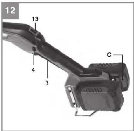
natural_image
Close-up of a black handheld power switch with a label and arrow, no readable text or symbols on the device itself.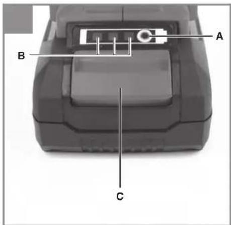
natural_image
Diagram showing two hand positions with a tool, no text or symbols present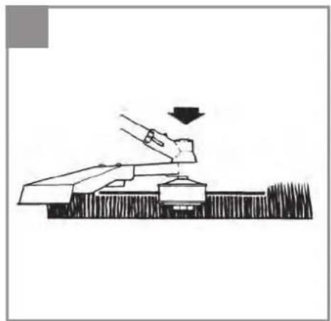
natural_image
Simple line drawing of a hand pressing down on a mechanical component (no text or symbols)
natural_image
Close-up of a mechanical device with black and gray components, no visible text or symbols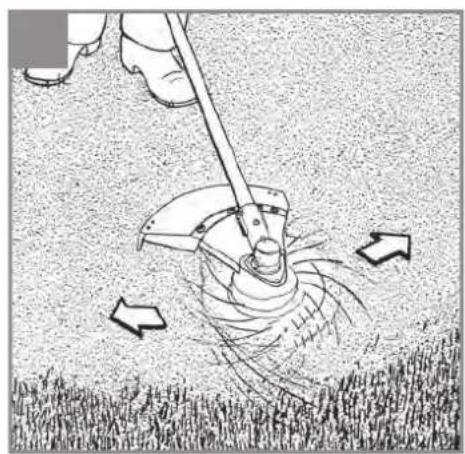
natural_image
Illustration of a person using a manual tool to lift a large saw on grass, with arrows indicating motion (no text or symbols)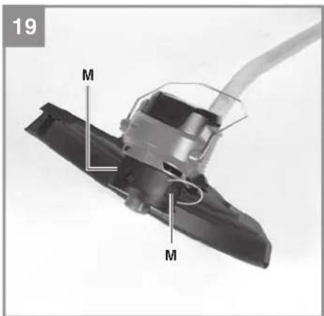
natural_image
Mechanical component with spring and threaded shaft, labeled 'F' (no text or symbols beyond label)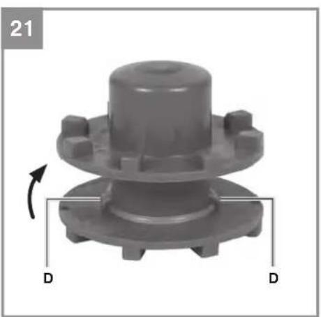
natural_image
Mechanical component with flanged base and central hub, labeled 'D' and page number 21 (no text or symbols on the component itself)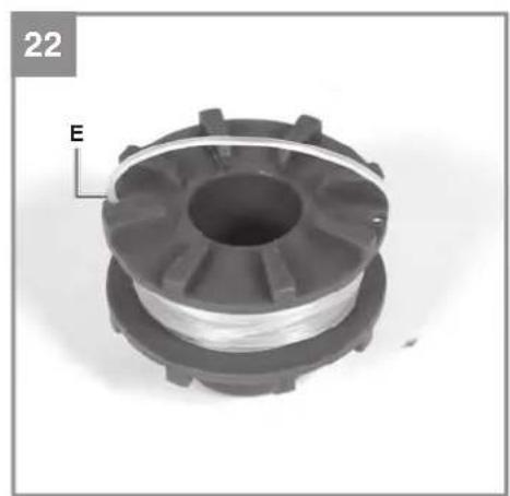
natural_image
Close-up of a mechanical component with a spool and threaded shaft, labeled 'E' and page number 22 (no other text or symbols)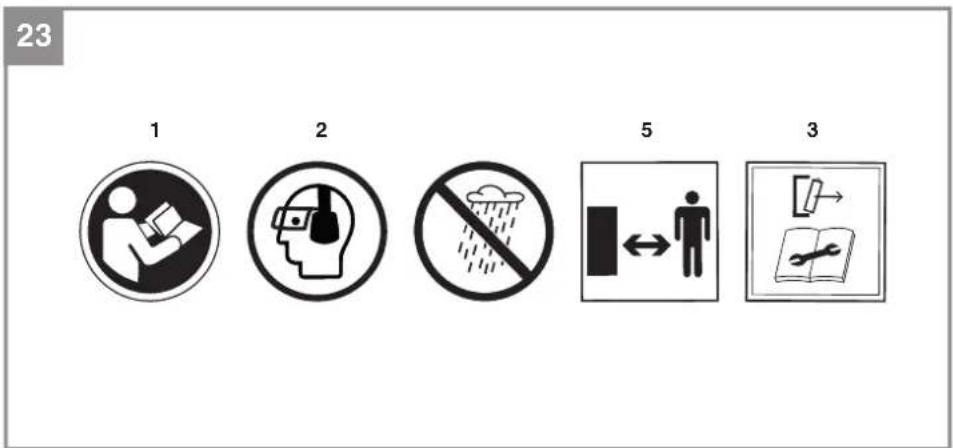
D
Gefahr!
When using equipment, a few safety precautions must be observed to avoid injuries and damage. Please read the complete original operating instructions and safety information with due care. Keep these operating instructions in a safe place so that the information is available at all times. If you give the equipment to any other person, hand over these original operating instructions and the safety information as well. We cannot accept any liability for damage or accidents which arise due to failure to follow these instructions and the safety information.
Explanation of the warning signs on the tool (see Fig. 23)
- Read the instruction manual before starting!
- Wear goggles and ear muff s!
- Do not use the tool in the rain or under wet conditions. If water gets inside the tool this will increase the risk of an electric shock or malfunction and can lead to injuries.
- Keep other people out of the danger area!
- Warning! Remove the battery before working on the tool.
1. Safety information
The corresponding safety information can be found in the enclosed booklet.
WARNING!
Read all safety warnings, instructions, illustrations and specifications provided with this power tool. Failure to follow all instructions listed below may result in electric shock, fi re and/or serious injury.
Save all warnings and instructions for future reference.
This equipment is not allowed to be used by children. Children should be supervised so that they do not play with the equipment. Children are not allowed to carry out the cleaning or maintenance. This equipment is not allowed to be used by people with limited physical, sensory or mental capacities or by those with insufficient knowledge or experience unless they are supervised or instructed by a person who is responsible for them.
2. Layout and items supplied
2.1 Layout (Fig. 1/2)
1 Battery mount
2 Support bar
3 On/Off switch
4 Safety lock-off
5 Strap attachment
6 Carrying strap
7 Guard hood
8 Spool housing
9 Edge guide
10 Motor housing
11 Union nut
12 Additional handle
12a Additional handle attachment
12b Handle screw
13 Speed selector
14 Top part of the long handle
15 Handle connecting piece
16 Bottom part of the long handle
17 String
18 Socket head screw
19 Assembly screw (4 pcs)
20 Hex key
2.2 Items supplied
Please check that the article is complete as specified in the scope of delivery. If parts are missing, please contact our service center or the sales outlet where you made your purchase at the latest within 5 working days after purchasing the product and upon presentation of a valid bill of purchase. Also, refer to the warranty table in the service information at the end of the operating instructions.
- Open the packaging and take out the equipment with care.
- Remove the packaging material and any packaging and/or transportation braces (if available).
- Check to see if all items are supplied.
- Inspect the equipment and accessories for transport damage.
- If possible, please keep the packaging until the end of the guarantee period.
Danger!
The equipment and packaging material are not toys. Do not let children play with plastic bags, foils or small parts. There is a danger of swallowing or suff ocating!
• Top section of the trimmer
• Bottom section of the trimmer with line spool
GB
- Guard hood
- Steady grip
- Hexagon key
- Harness
- Edge guide
- Support bar
- Socket head screw M6 x 60mm
• Assembly screw (4 pcs)
• Original operating instructions
• Safety information
3. Intended use
The equipment is designed for cutting lawns and grassed areas. It is not designed to be used for public facilities, parks, sports centers, along roadways, or in agriculture and forestry.
The operating instructions as supplied by the manufacturer must be kept and referred to in order to ensure that the equipment is properly used and maintained.
Important. This equipment must not be used for composting purposes (shredding) as this could result in injury or damage to property.
The equipment may be used only for the tasks it is designed to handle. Any other use is deemed to be a case of misuse. The user/operator and not the manufacturer will be liable for any damage or injuries of any kind resulting from such misuse.
Caution!
Residual risks
Even if you use this electric power tool in accordance with instructions, certain residual risks cannot be rules out. The following hazards may arise in connection with the equipment's construction and layout:
- Lung damage if no suitable protective dust mask is used.
- Damage to hearing if no suitable ear protection is used.
- Health damage caused by hand-arm vibrations if the equipment is used over a prolonged period or is not properly guided and maintained.
- Injuries and material damage caused by flying parts.
- Cut injuries if suitable protective clothing is not worn.
4. Technical data
Voltage....36Vd.c.
Speed n_0 .....7000 min ^-1
Cutting circle 0 35 cm
Protection class ....III
Weight: 3.05 kg
Caution!
The equipment is supplied without batteries and without a charger and is allowed to be used only with the lithium-ion batteries (two batteries) of the Power X-Change series!
The lithium-ion batteries of the Power X-Change series are allowed to be charged only with the Power-X charger.
Danger!
Sound and vibration
Sound and vibration values were measured in accordance with EN 62841.
Sound pressure level L_pA : 84.7 dB(A)
Uncertainty K_pA : 3 dB
Sound power level L_WA : 93.5 dB(A)
Uncertainty K_WA : 3 dB
Guaranteed sound power level L_WA : ...... 96 dB(A)
Wear ear-muff s.
The impact of noise can cause damage to hearing.
Total vibration values (vector sum of three directions) determined in accordance with EN 62841.
Handle
Vibration emission value a_n = 1.904 m/s^2
K uncertainty = 1.5 m/s ^4
Additional handle
Vibration emission value a_n=3.904 m/s^2
K uncertainty = 1.5 m/s²
The stated vibration emission levels and stated noise emission values were measured in accordance with a set of standardized criteria and can be used to compare one power tool with another.
The stated vibration emission levels and stated noise emission values can also be used to make an initial assessment of exposure.
GB
Warning:
The vibration and noise emission levels may vary from the level specified during actual use, depending on the way in which the power tool is used, especially the type of workpiece it is used for.
Limit the operating time!
All stages of the operating cycle must be considered (for example, times in which the electric tools are switched off and times in which the tool is switched on but operates without load).
Reduce noise generation and vibration to a minimum!
- Use only equipment that is in perfect condition.
- Maintain and clean the equipment regularly.
• Adapt your way of working to the equipment.
• Do not overload the equipment.
• Have the equipment checked if necessary. - Switch off the equipment when not in use.
- Wear gloves.
5. Before using the equipment
The equipment is supplied without batteries and without a charger!
5.1 Fitting the guard hood (Fig. 3)
Push the guard hood (Item 7) onto the mount on the motor housing as far as it will go and screw it securely in place with the hex screw (Item 18).
5.2 Fitting the edge guide (Fig. 4)
Pull the ends of the edge guide (Item 9) slightly apart and insert the ends in the holes provided on the left and right in the motor housing.
Remove the protective sticker from the string blade (Item 7a).
Warning! Take care not to cut yourself on the string blade.
5.3 Fitting the support bar (Fig. 5)
Push the support bar (Item 2) into the guides on the housing as far as the stop. Use the assembly screws (Item 19) to fasten the support bar at both ends.
5.4 Fitting the additional handle (Fig. 6)
Attach the additional handle (Item 12) to the attachment (Item 12a) and screw both parts together with the handle screw (Item 12b).
5.5 Fitting the long handle (Fig. 7)
Slot the top part of the long handle (Item 14) into the bottom part of the long handle (Item 16). Screw the handle connecting piece (Item 15) to the bottom part of the long handle with the union nut (Item 11) on the top part of the long handle.
5.6 Adjusting the additional handle (Fig. 8)
a) Adjusting the tilt
Undo the handle screw (Item 12b). Set the desired tilt of the additional handle (Item 12). Tighten the handle screw (Item 12b) again.
b) Shifting the additional handle
Open (a) the lock (Item 12c) and move the additional handle to the desired position. Close (b) the lock (Item 12c).
The adjustment range is limited by a rivet and the handle connecting piece.
5.7 Using the harness
The harness is intended to help you work safely and ergonomically. Always switch off the equipment before you release the harness – risk of injury.
Warning! Use only the carrying strap which is supplied with the tool. Never use more than one carrying strap at any time. To ensure that you can open and remove the carrying strap at any time, never carry several tools simultaneously.
- Hook the carabiner (Fig. 9/Item 6a) into the strap attachment.
- Slip the carrying strap over your shoulder (Fig. 10).
- Set the length of the harness in such a way that the cutting head runs parallel to the ground. To establish the optimum length of the harness, you should then make a few swinging movements without starting the equipment.
- The harness is equipped with a buckle. Press the hooks together (Fig. 11) if you need to put down the equipment quickly.
Each time before use, check the following :
- That the equipment is in perfect condition and that the safety devices and cutting devices are complete.
• That all screws are securely fastened.
• That all moving parts move smoothly.
GB
5.8 Installing the battery
Push the rechargeable batteries into the battery mounts provided on the left and right on the equipment (Fig. 1/Item 1). The battery will be heard to click into place when it has been pushed fully in (Fig. 12). To take out the battery, press the pushlock button (Fig. 12/Item C) and remove the battery.
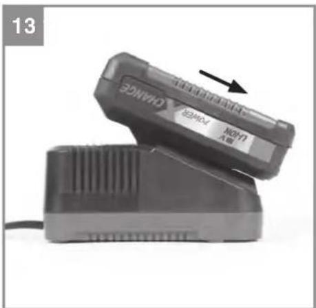
5.9 Charging the battery (Fig. 13)
- Take the battery pack out of the equipment. Do this by pressing the side pushlock buttons.
- Check that your mains voltage is the same as that marked on the rating plate of the battery charger. Insert the power plug of the charger into the mains socket outlet. The green LED will then begin to fl ash.
- Insert the battery pack into the battery charger.
- In section „Charger indicator“ you will find a table with an explanation of the LED indicator on the charger.
The battery pack can become a little warm during the charging. This is normal. If the battery pack fails to charge, check:
• whether there is voltage at the socket outlet
- whether there is good contact at the charging contacts
If the battery pack still fails to charge, send
• the charging unit
• and the battery pack
to our customer service center.
To ensure that items are properly packaged and delivered when you send them to us, please contact our customer service or the point of sale at which the equipment was purchased.
When shipping or disposing of batteries and cordless tools, always ensure that they are packed individually in plastic bags to prevent short circuits and fi res.
To ensure that the battery pack provides long service, you should take care to recharge it promptly. You must recharge the battery pack when you notice that the performance of the device drops. Never allow the battery pack to become fully discharged. This will cause it to develop a defect.
5.10 Battery capacity indicator (Fig. 14)
Press the switch for the battery capacity indicator (Item B). The battery capacity indicator (Item A) shows the charge status of the battery using 3 LEDs.
All 3 LEDs are lit:
The battery is fully charged.
2 or 1 LED(s) are lit:
The battery has an adequate remaining charge.
1 LED fl ashes:
The battery is empty, recharge the battery.
All LEDs blink:
The battery temperature is too low. Remove the battery from the equipment, keep it at room temperature for one day. If the fault reoccurs, this means that the rechargeable battery has undergone exhaustive discharge and is defective. Remove the battery from the equipment. Never use or charge a defective battery.
6. Operation
Please note that the statutory regulations governing noise abatement may differ from one location to another.
Danger! The guard hood must be fitted when carrying out work.
6.1 Switching the equipment on and off, adjusting the speed
6.1.1 Adjusting the speed (Fig. 12)
Warning! Set the speed only when the motor is at a standstill.
Push the switch (Item 13) into position "1" => Low speed, longer battery running time. Push the switch (Item 13) into position "2" => High speed, shorter battery running time.
6.1.2 Switching on
Press the left or the right safety lock-off (Item 4) and the On/Off switch (Item 3). Once the tool is running, you can release the safety lock-off.
Note: When you switch on in switch position "2", the motor might start up at a slightly reduced speed and not reach maximum speed until it is placed under load. This is not a fault.
GB
6.1.3 Switching off
Release the On/Off switch.
6.2 Practical tips
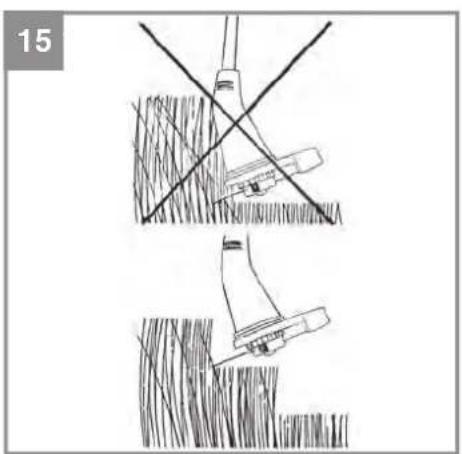
Practice all the work steps with the motor switched off and without the rechargeable battery before you start to use the equipment. Only ever cut grass that is dry. If the grass is long, the grass must be cut shorter in stages (Fig. 15).
Extending the cutting line (Fig. 16)
Danger! Do not use any kind of metal wire or metal wire encased in plastic in the line spool. This may cause serious injuries to the user.
The grass trimmer has a semi-automatic line extension system (automatic jog line feed). Each time you activate the semi-automatic line extension system, the line is automatically extended to ensure that you can cut your lawn with the perfect cutting width at all times. To extend the cutting line, run the motor and tap the line spool on the ground. This will automatically extend the line. The blade on the guard hood will cut the line to the permissible length. Please note that the more often you activate the semi-automatic line extension system, the more the line will wear.
Note: If the line is too long when you use the equipment for the fi rst time, the surplus end of it will be cut by the blade on the guard hood. If the line is too short when you start the equipment for the fi rst time, press the knob on the line spool and pull the line hard. When you then start the machine for the fi rst time the line will be cut to the perfect length automatically.
Using a brush or similar, carefully remove all residual grass from the underside of the guard hood at regular intervals.
Different cutting methods
Caution! To use the edge guide along walls or objects, swing the edge guide forward to the front (Fig. 4). Swing it up when not in use (Fig. 17).
Please note: Even if it is used carefully, cutting around foundations, stone or concrete walls, etc. will result in the line suffering above normal wear.
Trimming/mowing
Swing the trimmer from side to side in a scything motion. Always keep the line spool parallel to the ground. Check the site and decide what cutting height you require. Guide and hold the line spool at the required height to ensure that you cut evenly.
Low trimming
Hold the trimmer right in front of you at a slight angle so that the underside of the line spool is above the ground and the line strikes the correct target. Always cut away from yourself. Never draw the trimmer towards yourself.
Cutting along fences/foundations Edge guide recommended!
When cutting approach wire mesh fences, lath fences, natural stone walls and foundations slowly so that you can cut close to them without striking the obstacle with the line. If, for example, the line strikes stones, stone walls or foundations, it will wear or fray. If the line strikes wire fencing it will break.
Trimming around trees
Edge guide recommended!
When trimming around tree trunks, approach slowly so that the line does not strike the bark. Walk around the tree, cutting from left to right. Approach grass or weeds with the tip of the line and tilt the line spool forwards slightly. Warning: Take extreme care during mowing work. When doing such work keep a distance of 30 meters between yourself and other people or animals.
Mowing
For mowing you want to cut all the vegetation down to the ground. To do this, set the line spool at an angle of 30^ to the right. Place the handle in the required position. Remember the increased risk of injury to the user, watchers and animals and the danger of damaging other items due to objects (for example stones) being thrown out (Fig. 18).
GB
7. Cleaning, maintenance and ordering of spare parts
Danger!
Before putting away or cleaning the grass trimmer, switch off and remove the battery pack.
7.1 Cleaning
- Keep all safety devices, air vents and the motor housing free of dirt and dust as far as possible. Wipe the equipment with a clean cloth or blow it down with compressed air at low pressure.
• We recommend that you clean the equipment immediately after you use it. - Clean the equipment regularly with a damp cloth and some soft soap. Do not use cleaning agents or solvents; these may be aggressive to the plastic parts in the equipment. Ensure that no water can get into the interior of the equipment. The ingress of water into an electric tool increases the risk of an electric shock.
- Use a brush to remove deposits from the safety guard.
7.2 Replacing the line spool
Danger! Remove the battery packs!
- Fig. 19 Press the line spool housing together at the points marked M and remove the spool cover.
- Remove the empty string holder.
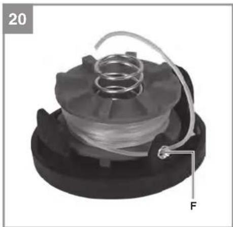
- Fig. 20 Thread the end of the line on the new line spool through the eyelet (F) in the spool cover and allow approx. 18 cm of line to project.
- Press the spool cover back into the line spool housing.
7.3 Replacing the cutting line
Danger! Remove the battery packs!
- Fig. 19 Press the line spool housing together at the points marked M and remove the spool cover.
- Remove the empty string holder.
- Remove any remaining cutting line if there is any.
- Fig. 21 Insert the new string into the string holder (D) inside the spool.
- While keeping the string under tension, wind it up in the direction indicated by the arrow.
-
Fig. 22 Hook the line, approx. 20 cm before the end of the line, into one of the line holders on the edge of the spool.
-
Fig. 20 Thread the end of the line on the new line spool through the eyelet (F) in the spool cover.
-
Pull the line sharply to release it from the line holder.
-
Press the spool cover back into the line spool housing.
When you start the equipment again the line will be cut to the perfect length automatically.
Caution! Bits of the nylon line could cause injury when fl ung out.
7.4 Maintenance
There are no other parts inside the equipment which require maintenance.
7.5 Ordering spare parts
Please provide the following information on all orders for spare parts:
• Model/type of the equipment
• Article number of the equipment
• ID number of the equipment
- Spare part number of the required spare part For our latest prices and information please go to www.Einhell-Service.com
Spare line spool Art. No.: 34.050.96
8. Disposal and recycling
The equipment is supplied in packaging to prevent it from being damaged in transit. The raw materials in this packaging can be reused or recycled. The equipment and its accessories are made of various types of material, such as metal and plastic. Defective components must be disposed of as special waste. Ask your dealer or your local council.
9. Storage
Store the equipment and accessories in a dark and dry place at above freezing temperature. The ideal storage temperature is between 5 and 30 °C. Store the electric tool in its original packaging.
GB
10. Transport
- Always carry the tool with one hand on the handle and the other on the additional handle. Do not carry the tool by the motor housing.
- Secure the tool against slipping if transporting it by car.
- If possible, use the original packaging for transportation.
The reprinting or reproduction by any other means, in whole or in part, of documentation and papers accompanying products is permitted only with the express consent of the Einhell Germany AG.
Subject to technical changes
11. Faults
The equipment does not work:
Check that the battery is charged and whether the charging unit is working. If the equipment will not work in spite of the voltage supply being OK, please send it to the customer service address below.

For EU countries only
Never place any electric power tools in your household refuse.
To comply with European Directive 2012/19/EC concerning old electric and electronic equipment and its implementation in national laws, old electric power tools have to be separated from other waste and disposed of in an environment-friendly fashion, e.g. by taking to a recycling depot.
Recycling alternative to the return request:
As an alternative to returning the equipment to the manufacturer, the owner of the electrical equipment must make sure that the equipment is properly disposed of if he no longer wants to keep the equipment. The old equipment can be returned to a suitable collection point that will dispose of the equipment in accordance with the national recycling and waste disposal regulations. This does not apply to any accessories or aids without electrical components supplied with the old equipment.
Please note that batteries and lamps (e.g. light bulbs) must be removed from the tool before it is disposed of.
12. Charger indicator
| Indicator status Explanations and actions | ||
| Red LED Green LED | ||
| Off | Flashing | Ready for useThe charger is connected to the mains and is ready for use; there is no battery pack in the charger |
| On Off Charging | The charger is charging the battery pack in quick charge mode. The charging times are shown directly on the charger.Important! The actual charging times may vary slightly from the stated charging times depending on the existing battery charge. | |
| Off | On | The battery is charged and ready for use. (READY TO GO)The unit then changes over to gentle charging mode until the battery is fully charged.To do this, leave the rechargeable battery on the charger for approx. 15 minutes longer.Action:Take the battery pack out of the charger. Disconnect the charger from the mains supply. |
| Flashing Off | Adapted charging | The charger is in gentle charging mode.For safety reasons the charging is performed less quickly and takes more time. The reasons can be:- The rechargeable battery has not been used for a very long time.- The battery temperature is outside the ideal range.Action:Wait for the charging to be completed; you can still continue to charge the battery pack. |
| Flashing Flashing Fault | Charging is no longer possible. The battery pack is defective.Action:Never charge a defective battery pack.Take the battery pack out of the charger. | |
| On On Temperature fault | The battery pack is too hot (e.g. due to direct sunshine) or too cold (below 0^ ).Action:Remove the battery pack and keep it at room temperature (approx. 20^ ) for one day . | |
GB
Service information
We have competent service partners in all countries named on the guarantee certificate whose contact details can also be found on the guarantee certificate. These partners will help you with all service requests such as repairs, spare and wearing part orders or the purchase of consumables.
Please note that the following parts of this product are subject to normal or natural wear and that the following parts are therefore also required for use as consumables.
| Category Example | |
| Wear parts* Battery, Line spool holder | |
| Consumables* Line, Line spool | |
| Missing parts |
* Not necessarily included in the scope of delivery!
In the effect of defects or faults, please register the problem on the internet at www.Einhell-Service.com. Please ensure that you provide a precise description of the problem and answer the following questions in all cases:
• Did the equipment work at all or was it defective from the beginning?
• Did you notice anything (symptom or defect) prior to the failure?
• What malfunction does the equipment have in your opinion (main symptom)?
Describe this malfunction.
GB
Warranty certifi cate
Dear Customer,
All of our products undergo strict quality checks to ensure that they reach you in perfect condition. In the unlikely event that your device develops a fault, please contact our service department at the address shown on this guarantee card. You can also contact us by telephone using the service number shown. Please note the following terms under which guarantee claims can be made:
- These guarantee terms apply to consumers only, i.e. natural persons intending to use this product neither for their commercial activities nor for any other self-employed activities. These warranty terms regulate additional warranty services, which the manufacturer mentioned below promises to buyers of its new products in addition to their statutory rights of guarantee. Your statutory guarantee claims are not affected by this guarantee. Our guarantee is free of charge to you.
- The warranty services cover only defects due to material or manufacturing faults on a product which you have bought from the manufacturer mentioned below and are limited to either the rectification of said defects on the product or the replacement of the product, whichever we prefer. Please note that our devices are not designed for use in commercial, trade or professional applications. A guarantee contract will not be created if the device has been used by commercial, trade or industrial business or has been exposed to similar stresses during the guarantee period.
-
The following are not covered by our guarantee:
-
Damage to the device caused by a failure to follow the assembly instructions or due to incorrect installation, a failure to follow the operating instructions (for example connecting it to an incorrect mains voltage or current type) or a failure to follow the maintenance and safety instructions or by exposing the device to abnormal environmental conditions or by lack of care and maintenance.
- Damage to the device caused by abuse or incorrect use (for example overloading the device or the use or unapproved tools or accessories), ingress of foreign bodies into the device (such as sand, stones or dust, transport damage), the use of force or damage caused by external forces (for example by dropping it).
-
Damage to the device or parts of the device caused by normal or natural wear or tear or by normal use of the device.
-
The guarantee is valid for a period of 24 months starting from the purchase date of the device. Guarantee claims should be submitted before the end of the guarantee period within two weeks of the defect being noticed. No guarantee claims will be accepted after the end of the guarantee period. The original guarantee period remains applicable to the device even if repairs are carried out or parts are replaced. In such cases, the work performed or parts fitted will not result in an extension of the guarantee period, and no new guarantee will become active for the work performed or parts fitted. This also applies if an on-site service is used.
-
To make a claim under the guarantee, please register the defective device at: www.Einhell-Service.com. Please keep your bill of purchase or other proof of purchase for the new device. Devices that are returned without proof of purchase or without a rating plate shall not be covered by the guarantee, because appropriate identification will not be possible. If the defect is covered by our guarantee, then the item in question will either be repaired immediately and returned to you or we will send you a new replacement.
Of course, we are also happy offer a chargeable repair service for any defects which are not covered by the scope of this guarantee or for units which are no longer covered. To take advantage of this service, please send the device to our service address.
Also refer to the restrictions of this warranty concerning wear parts, consumables and missing parts as set out in the service information in these operating instructions.
F
Danger!
Negotovost K_pA : 3 dB
Svetle sve 3 LE-diode:
X 2006/42/EC
Annex IV
Notified Body:
Reg. No.:
X 2000/14/EC_2005/88/EC
Annex V
X Annex VI
Noise: measured L_WA = 93.5 dB (A); guaranteed L_WA = 96 dB (A)
P = kW; L/∅ = 35 cm
Notified Body: TÜV Süd Industrie Service GmbH (NB 0036)
2012/46/EU_(EU)2016/1628 Emission No.:
Standard references: EN 62841-1; IEC 62841-4-4; EN IEC 55014-1; EN IEC 55014-2
Subject to change without notice
Archive-File/Record: NAPR026248
Documents registrar: Josef Landauer
Wiesenweg 22, D-94405 Landau/Isar
* 1. GB Cordless grass trimmer - F Coupe-bordane a accumulator - Tlimmar a bettoria - DVNX Battedreven grästrimmer - S Betterdirken grästrimmer - CZ Akulatumorak snowste soxaksa - SK Akulatumorak strunevt kosaka - NK Aocugezontrimmer - R Esportodens de cezdip de baterla - FIN Akulayttömmen rachotrimmar - SLO Batejksa kositima za travo - N Akul- pärzattrimmer - RO Trimmar peniu gazan cu accumulator - GIN Myogen mörupcoupou jertu irztapog - P gasodor de reva sam lo - HR3N Akulatumorak trimer za travljak - RS Akulatumorski trimer za travljak - PL Akulatumorski trimer za travljak - LV Akulatumorski trimer za travljak - LV Akulatumorski trimer za travljak - LV Akulatumorski trimer za travljak - LV Akulatumorski trimer za travljak - LV Akulatumorski trimer za travljak - LV Akulatumorski trimer za travljak - LV Akulatumorski trimer za travljak - LV Akumploratora kosanha za podlăvămeșten na treba - OKI Akulutropora kosana angemiosokara - MNI Vilner za treba na beleriis

Declaration of conformity
We, Einhell UK Ltd
Champions Business Park, First Floor Unit 10, Arrowe Brook Rd, Upton, Wirral CH49 0AB, United Kingdom
declare the conformity to UK standards and legislation was assessed for:
Cordless Lawn Trimmer GP-CT 36/35 Li BL (Einhell)
UK legislation
□ Simple Pressure Vessels (Safety) Regulation
□ Electrical Equipment (Safety) Regulation
□ Radio Equipment Regulation
□ Personal Protective Equipment Regulation
☐ The Ecodesign for Energy-Related Products and Energy Information Regulation
X The Restriction of the Use of Certain Hazardous Substances in Electrical and Electronic Equipment Regulation
X Noise Emission in the Environment by Equipment for use Outdoors Regulation
X Electromagnetic Compatibility Regulation
□ Measuring Instruments Regulation
□ Pressure Equipment (Safety) Regulation
□ Annex V
X Annex VI
Noise:measured L_wA = 93.5 dB (A); guaranteed L_wA = 96 dB (A)
P = kW; L/∅ = 35 cm
X Supply of Machinery (Safety) Regulation
□ Annex IV
UK Approved Body:
UKTE Certifi cate No.:
Standards: EN 62841-1; IEC 62841-4-4; EN IEC 55014-1; EN IEC 55014-2
Wirral, 2023.03.16

Tom Chambers, Managing Director Einhell UK Ltd.
Archive-File/Record: NAPR026248
Article Number: 34.113.30 I.-No.: 21012
Subject to change without notice Wiesenweg 22, 94405 Landau/Isar, Germany
Documents registrar: Josef Landauer
EH 05/2023 (01)