
TEL695WP 125 Gala Edition - Dryer MIELE - Free user manual and instructions
Find the device manual for free TEL695WP 125 Gala Edition MIELE in PDF.

| Brand | Miele |
| Model | TEL695WP 125 Gala Edition |
| Product type | Tumble dryer |
| Load capacity | 8 kg |
| Dimensions (H x W x D) | 85 x 60 x 60 cm |
| Weight | 53 kg |
| Power supply | 230 V, 50 Hz, 10 A |
| Heating power | 2000 W |
| Drying type | Heat pump |
| Energy class | A+++ |
| Drying programs | Cotton, Synthetics, Wool, Delicates, Express, etc. |
| PerfectDry system | Yes, perfect drying thanks to sensor technology |
| FragranceDos | Yes, automatic fragrance dosing |
| Filter maintenance | After each cycle, clean the lint filter |
| Condenser cleaning | Regularly, approximately every 10 cycles |
| Water reservoir | Drain after each cycle |
| Child safety | Yes, key lock |
| Stacking kit | Included for mounting on washing machine |
| Spare parts | Filters, seals, stacking kit, etc. |
| Country of origin | Germany |
Frequently Asked Questions - TEL695WP 125 Gala Edition MIELE
User questions about TEL695WP 125 Gala Edition MIELE
0 question about this device. Answer the ones you know or ask your own.
Ask a new question about this device
Download the instructions for your Dryer in PDF format for free! Find your manual TEL695WP 125 Gala Edition - MIELE and take your electronic device back in hand. On this page are published all the documents necessary for the use of your device. TEL695WP 125 Gala Edition by MIELE.
USER MANUAL TEL695WP 125 Gala Edition MIELE
natural_image
Technical line drawing of a mechanical assembly with a circular component inserted into a base frame (no text or symbols)natural_image
Diagram of a mechanical device with directional arrows indicating motion or force, showing internal components and alignment (no text or symbols)natural_image
Technical illustration of a mechanical assembly with a magnified inset showing a component detail (no text or symbols present)natural_image
Technical line drawing of a mechanical assembly with a circular component inserted into a base frame (no text or symbols)natural_image
Diagram of a mechanical device with directional arrows indicating motion or force, showing internal components and alignment (no text or symbols)natural_image
Technical illustration of a mechanical assembly with a magnified inset showing a component detail (no text or symbols present)■ Skru tørretumblerens 4 ben af.
natural_image
Technical line drawing of a mechanical assembly with a circular component inserted into a base frame (no text or symbols)natural_image
Diagram of a mechanical device with directional arrows indicating motion or force, showing internal components and alignment (no text or symbols)natural_image
Technical illustration of a mechanical assembly with a magnified inset showing a component detail (no text or symbols present)Risk of tipping over due to incorrect washer-dryer stack statics.
The washing machine must never be mounted on the tumble dryer. This will impair the statics of the washer-dryer stack.
Always use the washing machine as the base for the washer-dryer stack.
Washer-dryer stack dimensions
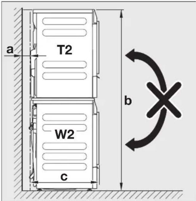
a = at least 2 cm
b = 172 cm
c = 65 cm
Components of the washer-dryer stacking kit
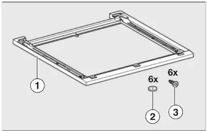
① Frame
② Sealing rings
③ Countersunk screws for fastening the stacking kit in place
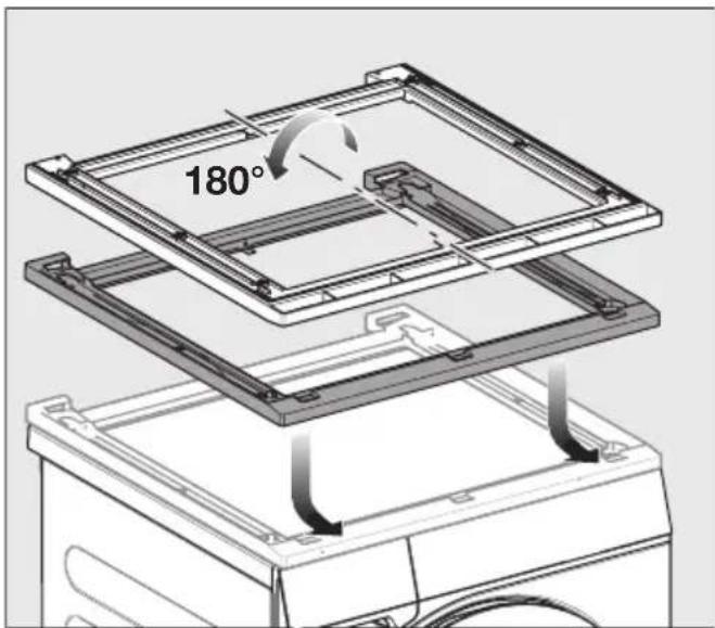
Preparing the stacking kit
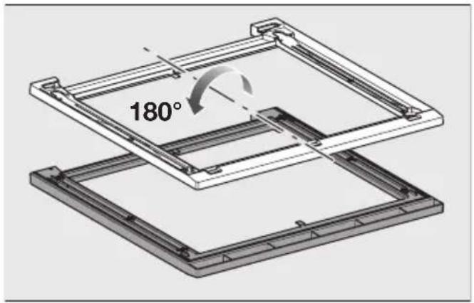
■ Place the stacking kit upside down on a soft surface, e.g., a blanket.
natural_image
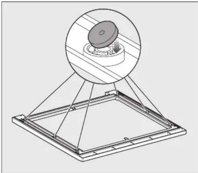
Technical line drawing of a mechanical assembly with a circular component inserted into a base frame (no text or symbols)■ Stick the 6 sealing rings to the underside of the stacking kit.
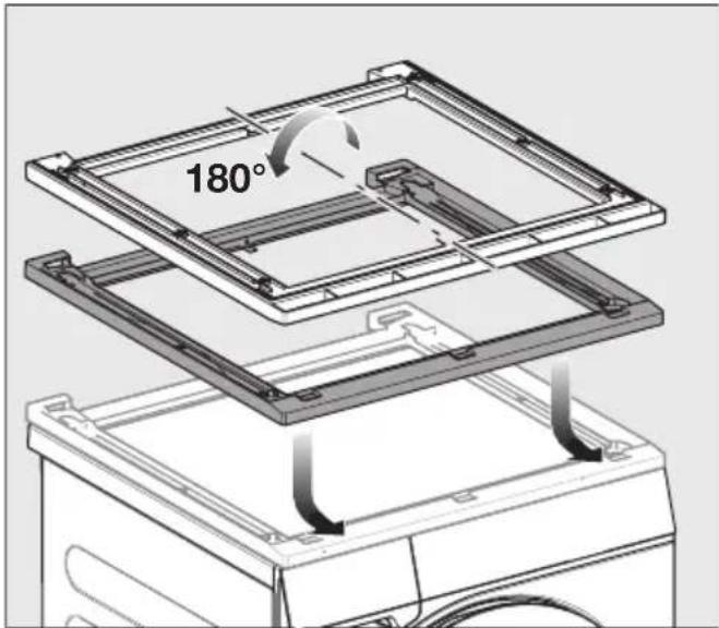
■ Turn the stacking kit the right way up and place it on the washing machine lid.
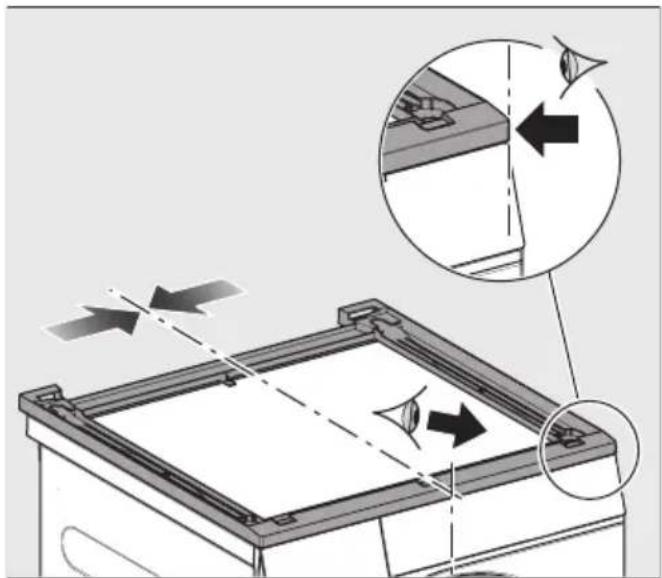
Aligning the stacking kit

natural_image
Diagram of a mechanical device with directional arrows indicating motion or force, showing internal components and alignment (no text or symbols)■ Align the stacking kit flush with the washing machine on the left and right and at the front.

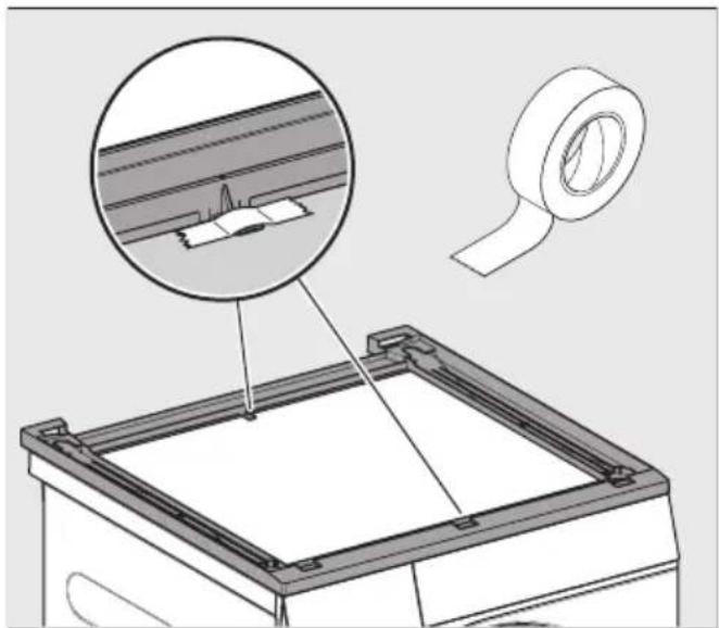
natural_image
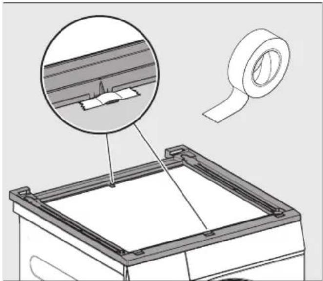
Technical illustration of a mechanical assembly with a magnified inset showing a component detail (no text or symbols present)■ Fix the aligned stacking kit to the lid with adhesive tape.
Fastening the stacking kit in place
■ Use the 6 countersunk screws included with the delivery to fasten the stacking kit in place.
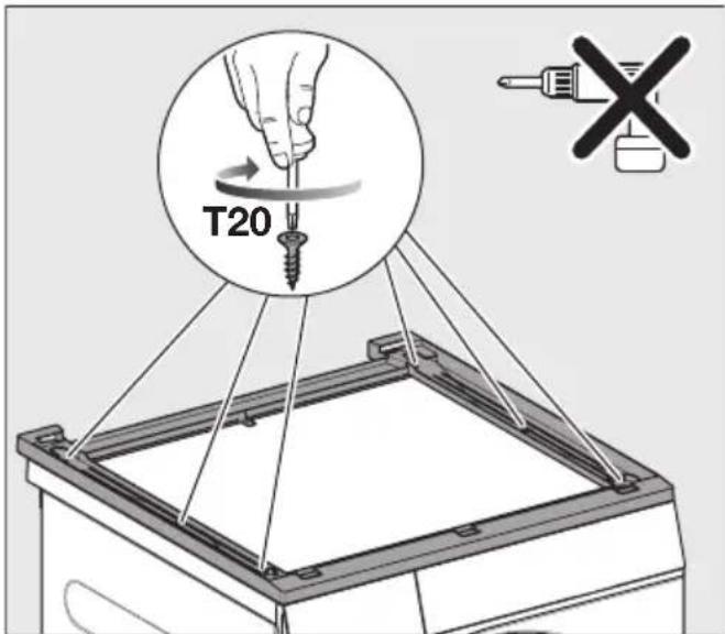
■ Carefully screw the stacking kit onto the washing machine lid by hand. Do not overtighten the screws.
Preparing the tumble dryer
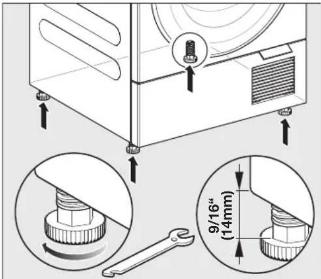
■ Unscrew the 4 tumble dryer feet.
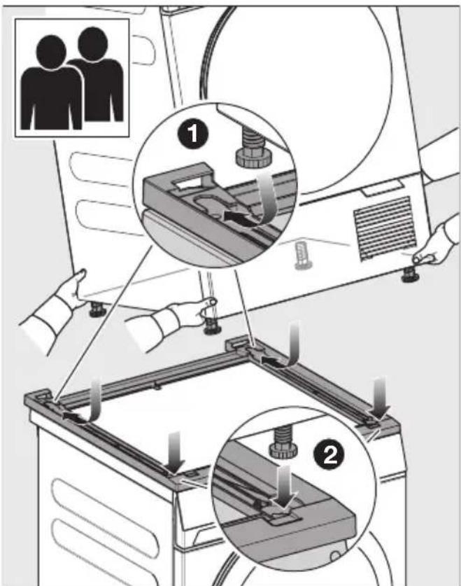
Mounting the tumble dryer on the washer-dryer stacking kit
Placing the tumble dryer on the washing machine
This step must be carried out by 2 people.
■ Lift the tumble dryer and tilt it back slightly for installation.
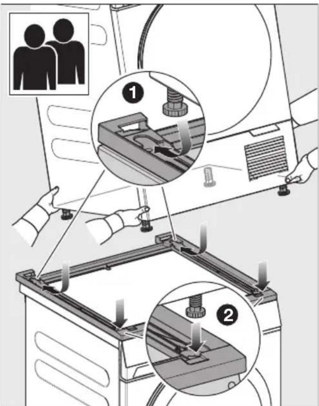
1 Place the rear feet in the stacking kit first and push them all the way back.
② Then set down the front feet.
The tumble dryer feet are positioned securely in the stacking kit.
Removing the washer-dryer stacking kit
When the washer-dryer stacking kit is removed, holes remain in the lid of the washing machine. The holes in the lid mean that the washing machine is no longer leak-proof. The washing machine must not be operated.
Options for sealing the holes:
- Seal the holes with silicone.
- Have a new lid fitted by a professional.
natural_image
Technical line drawing of a mechanical assembly with a circular component inserted into a base frame (no text or symbols)natural_image
Diagram of a mechanical device with directional arrows indicating motion or force, showing internal components and alignment (no text or symbols)natural_image
Technical illustration of a mechanical assembly with a magnified inset showing a component detail (no text or symbols present)natural_image
Technical line drawing of a mechanical assembly with a circular component inserted into a base frame (no text or symbols)natural_image
Diagram of a mechanical device with directional arrows indicating motion or force, showing internal components and alignment (no text or symbols)natural_image
Technical illustration of a mechanical assembly with a magnified inset showing a component detail (no text or symbols present)natural_image
Technical diagram of a mechanical assembly with a circular component inserted into a base frame (no text or symbols)natural_image
Diagram of a mechanical device with directional arrows indicating motion or force, showing internal components and alignment (no text or symbols)natural_image
Technical illustration of a mechanical assembly with a magnified inset showing a component detail (no text or symbols present)natural_image
Technical line drawing of a mechanical assembly with a circular component inserted into a base frame (no text or symbols)■ Zalijepite 6 brtvenih prstena na donju stranu veznog elementa.

■ Okrenite vezni element i postavite ga na poklopac perilice rublja.
Poravnanje veznog elementa
natural_image
Diagram of a mechanical device with directional arrows indicating motion or force, showing internal components and alignment (no text or symbols)natural_image
Technical illustration of a mechanical assembly with a magnified inset showing a component detail (no text or symbols present)■ Odvrnite 4 nožice sa sušilice rublja.
Postavljanje sušilice rublja na vezni element
Postavljanje sušilice na perilicu rublja
Za ovaj su korak potrebne 2 osobe.
■ Podignite sušilicu i lagano je nagnite unatrag kod postavljanja.
1 Prvo stavite stražnje nožice u vezni element i gurnite ih do kraja unatrag.
2 Zatim namjestite i spustite prednje nožice.
Nožice sušilice rublja čvrsto stoje u veznom elementu.
natural_image
Technical line drawing of a mechanical assembly with a circular component inserted into a base frame (no text or symbols)natural_image
Diagram of a mechanical device with directional arrows indicating motion or force, showing internal components and alignment (no text or symbols)natural_image
Technical illustration of a mechanical assembly with a magnified inset showing a component detail (no text or symbols present)natural_image
Technical line drawing of a mechanical assembly with a circular component inserted into a base frame (no text or symbols)natural_image
Diagram of a mechanical device with directional arrows indicating motion or force, showing internal components and alignment (no text or symbols)natural_image
Technical illustration of a mechanical assembly with a magnified inset showing a component detail (no text or symbols present)■ Fest den justerte mellomsatsen til dekselet med klebebånd
natural_image
Technical line drawing of a mechanical assembly with a circular component inserted into a base frame (no text or symbols)natural_image
Diagram of a mechanical device with directional arrows indicating motion or force, showing internal components and alignment (no text or symbols)natural_image
Technical illustration of a mechanical assembly with a magnified inset showing a component detail (no text or symbols present)natural_image
Technical line drawing of a mechanical assembly with a circular component inserted into a base frame (no text or symbols)natural_image
Diagram of a mechanical device with directional arrows indicating motion or force, showing internal components and alignment (no text or symbols)natural_image
Technical illustration of a mechanical assembly with a magnified inset showing a component detail (no text or symbols present)natural_image
Technical line drawing of a mechanical assembly with a circular component inserted into a base frame (no text or symbols)natural_image
Diagram of a mechanical device with directional arrows indicating motion or force, showing internal components and alignment (no text or symbols)natural_image
Technical illustration of a mechanical assembly with a magnified inset showing a component detail (no text or symbols present)natural_image
Technical line drawing of a mechanical assembly with a circular component inserted into a base frame (no text or symbols)natural_image
Diagram of a mechanical device with directional arrows indicating motion or force, showing internal components and alignment (no text or symbols)natural_image
Technical diagram showing a mechanical assembly with a magnified inset of a component detail (no text or symbols present)natural_image
Technical line drawing of a mechanical assembly with a circular component inserted into a base frame (no text or symbols)natural_image
Diagram of a mechanical device with directional arrows indicating motion or force, showing internal components and alignment (no text or symbols)■ Montážnu sadu zarovnajte do jednej roviny s práčkou na l'avej a pravej strane a vpredu.

natural_image
Technical illustration of a mechanical assembly with a magnified inset showing a component detail (no text or symbols present)■ Zafixujte zarovnanú montážnu sadu na veku pomocou lepiacej pásky
natural_image
Technical line drawing of a mechanical assembly with a circular component inserted into a base frame (no text or symbols)natural_image
Diagram of a mechanical device with directional arrows indicating motion or force, showing internal components and alignment (no text or symbols)■ Vezni element poravnajte levo, desno in spredaj s pralnim strojem.
natural_image
Technical illustration of a mechanical assembly with a magnified inset showing a component detail (no text or symbols)■ Poravnan vezni element fiksirajte z lepilnim trakom na pokrov.
natural_image
Technical line drawing of a mechanical assembly with a circular component inserted into a base frame (no text or symbols)■ Zalepite 6 zaptivnih prstenova na donju stranu veznog elementa.
■ Okrenite vezni element i postavite ga na poklopac mašine za pranje veša.
natural_image
Diagram of a mechanical device with directional arrows indicating motion or force, showing internal components and alignment (no text or symbols)■ Poravnajte vezni element tako da levo, desno i napred bude u ravni sa mašinom za pranje veša.
natural_image
Technical illustration of a mechanical assembly with a magnified inset showing a component detail (no text or symbols present)- Odvrnite 4 nožice mašine za sušenje veša.
Montaža mašine za sušenje veša na vezni element mašina za pranje i sušenje
Postavljanje mašine sa sušenje veša na mašinu za pranje veša
Za ovaj korak su potrebne 2 osobe.
1 Prvo postavite zadnje nožice u vezni element i gurnite ih skroz nazad.
2 Zatim spustite prednje nožice.
Nožice mašine za sušenje veša čvrsto stoje u veznom elementu.