
CMXCAFG190643 - Cleaning spray Craftsman - Free user manual and instructions
Find the device manual for free CMXCAFG190643 Craftsman in PDF.

| Product Type | Manual Pump Cleaning Sprayer |
| Brand | Craftsman |
| Model | CMXCAFG190643 |
| Tank Capacity | Approximately 1.9 liters (not exactly specified, reasonable estimate) |
| Operating Pressure | Generated by manual pump, no numerical value provided |
| Tank Material | Chemical-resistant plastic |
| Hose Length | Approximately 1.2 meters (estimate) |
| Wand Length | 14 inches (about 35.6 cm) |
| Included Nozzles | Low-flow foaming nozzle, high-flow foaming nozzle, adjustable cone nozzle, tip adapter, Dry-Touch adapter |
| Weight (approximate) | Approximately 0.7 kg (estimate) |
| Power Source | Manual (hand pump) |
| Main Functions | Spraying non-flammable liquids, cleaning, applying diluted chemicals |
| Maintenance | Clean after each use, lubricate piston O-ring if necessary |
| Cleaning | Rinse with clean water, spray water for 30 seconds to clean hose |
| Safety | Do not use flammable liquids, wear goggles and gloves, release pressure before disassembly |
| Spare Parts and Repairability | O-ring, valve, shut-off device, hose: replaceable; genuine parts recommended |
| Warranty | 3-year limited warranty (material and workmanship defects) |
| Customer Service | 1-888-331-4569 (toll-free), www.craftsman.com |
| Prohibited Uses | Flammable liquids, acids, caustics, hot water; do not use with air compressor |
| Included Accessories | Tank, pump, reinforced hose, shut-off device, 14" wand, multiple nozzles |
Frequently Asked Questions - CMXCAFG190643 Craftsman
User questions about CMXCAFG190643 Craftsman
0 question about this device. Answer the ones you know or ask your own.
Ask a new question about this device
Download the instructions for your Cleaning spray in PDF format for free! Find your manual CMXCAFG190643 - Craftsman and take your electronic device back in hand. On this page are published all the documents necessary for the use of your device. CMXCAFG190643 by Craftsman.
USER MANUAL CMXCAFG190643 Craftsman
Thank you for choosing a CRAFTSMAN product!
At CRAFTSMAN, we have 90 years of quality and innovation. Together, we are makers.
Please take a moment to read this manual before operating your new sprayer. Understanding the safety warnings and cautions is important before using your new purchase safely.
Definitions: Safety Alert Symbols and Words
This instruction manual uses the following safety alert symbols and words to alert you to hazardous situations and your risk of personal injury or property damage.

ER: Indicates an imminently hazardous situation which, if not avoided, will result in death or serious injury.

ING: Indicates a potentially hazardous situation which, if not avoided, could result in death or serious injury.

ON: Indicates a potentially hazardous situation which, if not avoided, may result in minor or moderate injury.

without word) Indicates a safety related message.
NOTICE: Indicates a practice not related to personal injury which, if not avoided, may result in property damage.
Fig. A
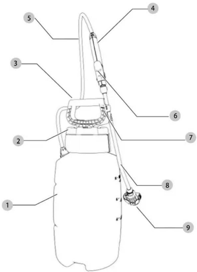
COMPONENTS
1 Tank
2 Splash Cap
3 Pump Handle
4 Premium Shut-off
5 Reinforced Hose
6 Trigger with Lock-on Feature
7 Wand Storage
8 14" Wand
9 Foaming Nozzle

IING: To reduce the risk of injury, read the
instruction manual
If you have any questions or comments about this or any product, call CRAFTSMAN toll free at: 1-888-331-4569.
CMXCAFG190643
SAFETY WARNINGS
WARNING: The sprayer is operated with liquid under pressure. Failure to observe CAUTION and to follow instructions for operating and cleaning can cause tank, hose and other parts to be weakened and rupture under pressure. This can result in serious injury from high pressure discharge of liquids or forcible ejection of parts. DO NOT USE FLAMMABLE MATERIALS IN THIS SPRAYER. Material could ignite or explode, causing serious injury and/or possible death. For safe use of this product, you must read and follow all instructions before use.
Test sprayer with water before using any chemicals.
SAFETY PRECAUTIONS: Read owner's manual completely before operating this sprayer.
• Always wear safety goggles, gloves, and protective clothing when using sprayer.
- Read and follow all instructions and cautions on label of products used in this sprayer.
- Never use flammable liquids, caustics, acids, or hot water in this tank.
- Do not leave sprayer in the sun when not in use.
- Spray when air is calm to prevent drift of chemicals.
- Do not use sprayer near open flame or anything that could cause ignition of the spray.
• Always inspect the hose and all hose connections before each use. A damaged hose, or loose hose connection can result in unintended exposure to the pressurized chemical, resulting in serious injury or property damage.
- Do not lift or carry sprayer by the hose, shut-off valve, or wand extension. Carry by pump handle only, making sure handle is properly locked in place before lifting.
- Do not pressurize with any mechanical device such as an air compressor, since this can create dangerous pressure level and bursting of parts resulting in serious injury. Only use original or replacement pump supplied by the original manufacturer.
- Do not store chemicals in this tank.
• Always release pressure when sprayer is not in use and before removing pump from tank.
- Do not stand with face or body over top of tank when pumping or loosening pump, to prevent pump and/or solution from striking you, resulting in serious injury.
- Clean and rinse sprayer thoroughly after each use.
- Never attempt to alter sprayer from original condition.
• Always use replacement parts from original manufacturer.
- Keep the sprayer and all chemicals out of the reach of children and pets.
ASSEMBLY INSTRUCTIONS
WARNING: Do not attempt to heat or alter hose, hose nut or barb prior to assembly.
It is recommended to test the sprayer using plain tap water before spraying chemicals. Test all connections for possible leaks. Use proper eye protection while testing. If sprayer does not pass the water test, call our Customer Service Center before using sprayer with chemicals. Make sure hose is not cracked or frayed and does not show signs of swelling. Make sure hose is securely connected to sprayer. DO NOT USE TOOLS TO TIGHTEN HOSE NUT.
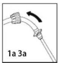
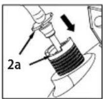
Assemble Hose to Tank
1a. Slide hose nut back on hose to expose hose barb.
2a. Push hose barb into tank until it stops. Align hose barb tabs with cutouts in tank.
3a. Slide hose nut into place and turn clockwise to tighten.
natural_image
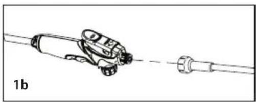
Illustration of a hand holding a small tool with a curved arrow, no text or symbols presentAssemble Wand to Shut-off
1b. Install the wand onto the shut-off assembly and tighten the nut securely.
natural_image
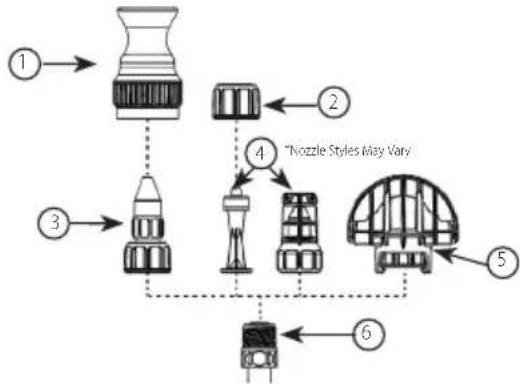
Diagram of a mechanical device connected to a shaft, labeled '1b' (no text or symbols on the diagram itself)Install the Nozzle
Select using nozzle chart.
flowchart
graph TD
    1["Top Top"] --> 2["Bottom Left"]
    3["Bottom Left"] --> 4["Bottom Right"]
    4 --> 5["Central Structure"]
    5 --> 6["Bottom Right"]
    style 1 fill:#f9f,stroke:#333
    style 2 fill:#ccf,stroke:#333
    style 3 fill:#cfc,stroke:#333
    style 4 fill:#fcc,stroke:#333
    style 5 fill:#cff,stroke:#333
    style 6 fill:#ffc,stroke:#333
    note right of 4: "Nozzle Styles May Vary"
1 Dry-TouchTM Adapter
2 Cap Nut
3 Adjustable Cone Nozzle
4 Low-Volume Foaming Nozzle
5 High Volume Foaming Nozzle
6 Wand
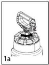
Fill the tank to the desired level.
1a. REMOVE PUMP: Turn handle counter-clockwise
2a. INSTALL PUMP: Turn handle clockwise until tightly sealed on tank
natural_image
Mechanical component diagram showing a rotating arm and base mount (no text or symbols)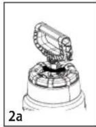
natural_image
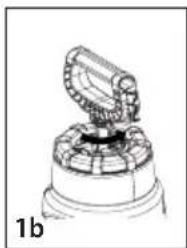
Technical line drawing of a mechanical component with a central assembly and base (no text or symbols)Pressurizing
Make sure the shut-off trigger is not locked in the "in use" position
1b. Push down on the handle and turn counter-clockwise to unlock the handle.
2b. Pump handle in a smooth up and down motion until pressure builds up.
3b. Push down on handle, turn clockwise to lock into place.
natural_image
Technical line drawing of a mechanical component with a central rotating element (no text or symbols)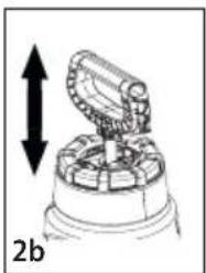
natural_image
Diagram of a mechanical device with an upward arrow and label '2b' (no readable text or symbols)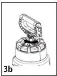
natural_image
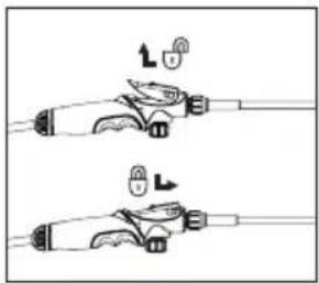
Technical line drawing of a mechanical component with a central knob and base (no text or symbols)Spraying and Locking
-
Squeeze shut-off trigger to begin spraying.
-
Release shut-off trigger to stop spraying.
-
For continuous spraying, squeeze the trigger and slide into locked position as shown.
natural_image
Diagram showing two mechanical components with directional arrows indicating motion (no text or symbols)Finish
- Depressurize
a. Lay tank on its side with the hose outlet on the bottom. Direct nozzle away from face and body and squeeze the shut-off handle until unit stops spraying. This will release the pressure in the tank.
-
Turn the pump handle counter-clockwise to remove pump.
-
Empty any remaining liquid according to the product disposal directions.
-
Follow cleaning instructions.
Cleaning
-
Fill the tank with clean tap water. Replace the pump and tighten securely.
-
Agitate the tank to rinse the chemicals from the tank and pump.
-
Remove the pump and empty the contents according to the product disposal instructions.
-
Refill the tank with clean tap water.
-
Make sure the pump is free of dirt and debris, and re-install into the tank. Tighten securely.
-
Pressurize the tank as described in the pressurizing section.
-
Direct the nozzle away from yourself and squeeze the shut-off trigger for at least 30 seconds to clean the hose and shut-off.
-
Release pressure as described in the finishing section.
-
Remove the pump and empty contents according to the product disposal instructions.
-
Repeat steps 1-9 until thoroughly cleaned.
Sprayer Storage
-
Sprayer tank should be hung upside down, with the pump removed.
-
Do not store or leave any solution in tank after use.
-
Store in warm, dry location out of direct sunlight.
-
Keep sprayer and all chemicals out of reach of children.
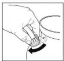
Disassembly & Reassembly
-
Remove pump from tank.
-
Squeeze tabs that lock cap and pull to unlock.
-
Remove handle, lubricate o-ring as required.
-
Replace pump cap, align tabs on pump cap and barrel, and push down until tabs lock into place.
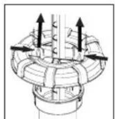
natural_image
Technical diagram of a mechanical assembly with directional arrows indicating motion or force (no text or symbols present)
natural_image
Mechanical assembly diagram showing a valve or pump component with a downward arrow indicating motion (no text or symbols present)Shut-off Maintenance
If shut-off clogs, remove the shut-off assembly and check for any obstructions at the dip tube or filter. If none present, disassemble the shut-off assembly. Clean the openings of any obstructions and re-assemble tightly securing all sections.

Three Year Limited Warranty
CRAFTSMAN will repair or replace, without charge, any defects due to faulty materials or workmanship for three years from the date of purchase. This warranty does not cover part failure due to normal wear or tool abuse. For further detail of warranty coverage and warranty repair information, visit www.craftsman.com or call
1-888-331-4569. This warranty does not apply to accessories or damage caused where repairs have been made or attempted by others. THIS LIMITED WARRANTY IS GIVEN IN LIEU OF ALL OTHERS, INCLUDING THE IMPLIED WARRANTY OF MERCHANTABILITY AND FITNESS FOR A PARTICULAR PURPOSE, AND EXCLUDES ALL INCIDENTAL OR CONSEQUENTIAL DAMAGES. Some states do not allow limitations on how long an implied warranty lasts or the exclusion or limitation of incidental or consequential damages, so these limitations may not apply to you. This warranty gives you specific legal rights and you may have other rights which vary in certain states or provinces.
| TROUBLESHOOTING GUIDEBE SURE TO FOLLOW SAFETY RULES AND INSTRUCTIONSFor assistance with your product, visit our website at www.craftsman.com for a list of service centers, or call CRAFTSMAN at 1-888-331-4569 | ||
| PROBLEMCAUSECORRECTION | ||
| Sprayer starts to spray when pumping or sprayer will not stop spraying when shut-off handle is released. | Shut-off lock is engaged. Squeeze shut-off | handle and disengage the lock. |
| Sprayer leaks at pump or sprayer does not build pressure. | 1. Dirt or debris on pump gasket or closure.2. Chipped, torn, swollen or defective pump gasket.3. Check valve at bottom of pump assembly.4. Inspect o-ring on piston.5. Loose hose. | 1. Clean dirt or debris from gasket or closure.2. Remove old gasket and replace with new.3. Replace if missing or damaged.4. Lubricate the pump as described in Regular Maintenance section.5. Re-insert hose barb, then tighten hose nut. |
| Sprayer material overflows through pump barrel or pump handle rises when handle is unlocked. | 1. Dirt or debris under check valve on pump.2. Chipped, torn or swollen pump check valve. | 1. Clean check valve and valve scaling surface on pump.2. Replace check valve. |
| Hose leaks at tank. 1. Loose hose. | 2. Cracked, swollen or faulty hose. | 1. Re-insert hose barb, then tighten hose nut.2. Replace shut-off assembly. |
| Hose leaks at shut-off. Swollen, slit or faulty hose Replace shut-off assembly. | ||
| Sprayer is difficult to pump. 1. Damaged | piston o-ring.2. Piston o-ring is dry. | 1. Replace piston o-ring.2. Lubricate the pump as described in Regular Maintenance section. |
| Nozzle drips when shut-off handle is released. | Dirt or debris in shut-off valve. 1. Replace shut-off assembly.2. See Shut-off Maintenance section. | |
| Sprayer tank leaks. Evidence of spray material escaping from the tank. | Replace entire sprayer. | |
| Nozzle tip leaks, poor spray pattern, partial spray or complete stoppage. | 1. O-ring is missing or damaged.2. Spray wand or nozzle clogged.3. Dip tube filter clogged. | 1. Replace o-ring at extension tip.2. If applicable to sprayer model, remove and clean the wand and nozzle.3. If applicable to sprayer model, remove and clean the dip tube filter. |
COMPONENTES
natural_image
Illustration of a hand holding a small mechanical component with a curved arrow indicating rotation (no text or symbols)natural_image
Diagram of a mechanical device with a shaft and housing, labeled '1b' (no text or symbols on the diagram itself)Instale la boquilla
natural_image
Technical line drawing of a mechanical component with a central rotating arm and base (no text or symbols)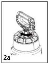
natural_image
Technical line drawing of a mechanical component with a central top and base (no text or symbols)Presurización
natural_image
Technical line drawing of a mechanical component with a central rotating element (no text or symbols)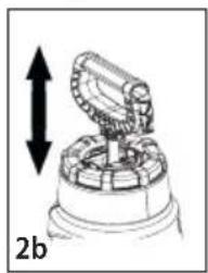
natural_image
Diagram of a mechanical component with an upward arrow indicating direction, labeled '2b' (no text or symbols on the diagram itself)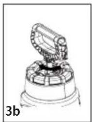
natural_image
Mechanical component diagram showing a rotating assembly with gears and housing (no text or symbols)Atomizar y asegurar
natural_image
Illustration of two mechanical components with arrows indicating motion direction (no text or symbols)Finalización
- Despresurice
natural_image
Technical diagram of a mechanical assembly with directional arrows indicating motion (no text or labels)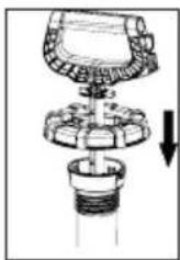
natural_image
Diagram of a mechanical assembly with a cylindrical component and a downward arrow indicating motion (no text or symbols)DESCRIPTION
natural_image
Hand holding a small mechanical component with a curved arrow indicating rotation (no text or symbols)natural_image
Technical line drawing of a mechanical component with a shaft and housing (no text or symbols)FRAnÇAis
Installation de la buse
natural_image
Technical line drawing of a mechanical component with a central knob and top view (no text or symbols)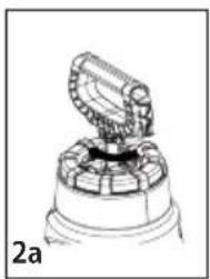
natural_image
Technical line drawing of a mechanical component with a central rotating element (no text or symbols)Pressurisation
natural_image
Technical line drawing of a mechanical device with a central component and base (no text or symbols)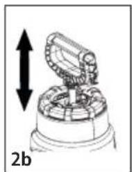
natural_image
Diagram of a mechanical device with an open lid and directional arrows, labeled '2b' (no text or symbols on the diagram itself)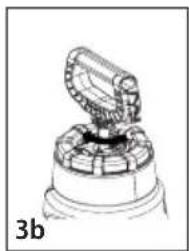
natural_image
Technical line drawing of a mechanical component with a central clamping mechanism (no text or symbols)Finir
- Dégagez la pression
natural_image
Technical diagram of a mechanical assembly with directional arrows indicating motion or force (no text or symbols present)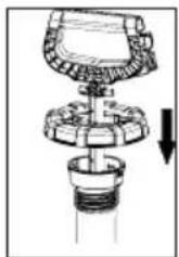
natural_image
Mechanical assembly diagram showing a valve or pump component with a downward arrow indicating force or direction (no text or symbols present)Product manufactured by:
The Fountainhead Group, Inc.
23 Garden Street, New York Mills, NY 13417 U.S.A
Manual No. 184611
Rev. C Date: 02/24/20
ECN 20-020
8.5"×5.5"

- Thank you for choosing a CRAFTSMAN product!
- Definitions: Safety Alert Symbols and Words
- COMPONENTS
- CMXCAFG190643
- SAFETY WARNINGS
- Test sprayer with water before using any chemicals.
- ASSEMBLY INSTRUCTIONS
- Assemble Hose to Tank
- Assemble Wand to Shut-off
- Install the Nozzle
- Cleaning
- Sprayer Storage
- Disassembly & Reassembly
- Shut-off Maintenance
- Three Year Limited Warranty
- COMPONENTES
- Instale la boquilla
- Finalización
- DESCRIPTION
- FRAnÇAis
- Installation de la buse
Brand : Craftsman
Model : CMXCAFG190643
Category : Cleaning spray