DCB548 - Battery DEWALT - Free user manual and instructions
Find the device manual for free DCB548 DEWALT in PDF.

| Product Type | Lithium-ion battery |
| Brand | DeWalt |
| Model | DCB548 |
| Nominal voltage | 20 V MAX* (18 V nominal) |
| Capacity | 6.0 Ah |
| Cell type | Lithium-ion |
| Weight | 0.62 kg |
| Dimensions (L x W x H) | 130 x 75 x 70 mm |
| Charge indicator | 3 level LED |
| Compatibility | DeWalt 20V MAX* tools |
| Electronic protection | Against overload, excessive discharge, short circuit, overheating |
| Operating temperature | -20 °C to 50 °C |
| Charging temperature | 4 °C to 40 °C |
| Typical charging time (standard charger) | 60 min |
| Maintenance and cleaning | Clean contacts with a dry cloth; store in a dry and cool place |
| Safety | Do not expose to water or fire; use only with DeWalt chargers |
| Spare parts and repairability | Protective cap available; sealed battery, not user-serviceable |
| Warranty | 2 years |
| Certifications | CE, EAC, RoHS |
Frequently Asked Questions - DCB548 DEWALT
User questions about DCB548 DEWALT
0 question about this device. Answer the ones you know or ask your own.
Ask a new question about this device
Download the instructions for your Battery in PDF format for free! Find your manual DCB548 - DEWALT and take your electronic device back in hand. On this page are published all the documents necessary for the use of your device. DCB548 by DEWALT.
USER MANUAL DCB548 DEWALT
If you have questions or comments, contact us.
Coil Siding and Fencing Nailer
Definitions: Safety Guidelines
The definitions below describe the level of severity for each signal word. Please read the manual and pay attention to these symbols.
ADANGER: Indicates an imminently hazardous situation which, if not avoided, will result in death or serious injury.
WARNING: Indicates a potentially hazardous situation which, if not avoided, could result in death or serious injury.
CAUTION: Indicates a potentially hazardous situation which, if not avoided, may result in minor or moderate injury.
NOTICE: Indicates a practice not related to personal injury which, if not avoided, may result in property damage.
IF YOU HAVE ANY QUESTIONS OR COMMENTS ABOUT THIS OR ANY DEWALT TOOL, CALL US TOLL FREE AT: 1-800-4-DEWALT (1-800-433-9258)
SAVE ALL WARNINGS AND INSTRUCTIONS FOR FUTURE REFERENCE
Important Safety Instructions
▲ WARNING: Do not operate this unit until you read this instruction manual for safety, operation and maintenance instructions.
WARNING: This product contains chemicals known to the State of California to cause cancer, and birth defects or other reproductive harm. Wash hands after handling.
⚠WARNING: Some dust contains chemicals known to the State of California to cause cancer, birth defects or other reproductive harm such as asbestos and lead in lead based paint.
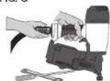
- Actuating tool may result in flying debris, collation material, or dust which could harm operator's eyes. The operator and all those persons in the general area should wear safety glasses with permanently attached side shields. Approved safety glasses are imprinted with the characters "Z87.1". It is the employer's responsibility to enforce the use of eye protection equipment by the tool operator and other people in the work area. (Fig. A)
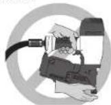
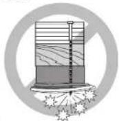
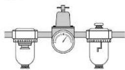
• Always wear appropriate personal hearing and other protection during use. Under some conditions and duration of use, noise from this product may contribute to hearing loss. (Fig. A) - Use only clean, dry, regulated air. Conden sation from an air compressor can rust and damage the internal workings of the tool. (Fig. B)
- Regulate air pressure. Use air pressure compatible with ratings on the nameplate of the tool. (Not to exceed 120 psi, 8.3 bar) Do not connect the tool to a compressor rated at over 200 psi. The tool operating pressure must never exceed 200 psi even in the event of regulator failure. (Fig. C)
FIG. A

FIG. B
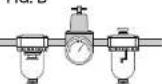
FIG. C
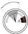
FIG. D
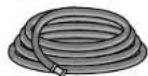
- Only use air hose that is rated for a maximum working pressure of at least 150 PSI (10.3 BAR) or 150% of the maximum system pressure, which ever is greater. (Fig. D)
- Do not use bottled gases to power this tool. Bottled compressed gases such as oxygen, carbon dioxide, nitrogen, hydrogen, propane, acetylene or air are not for use with pneumatic tools. Never use combustible gases or any other reactive gas as a power source for this tool. Danger of explosion and/or serious personal injury may result. (Fig. 8)
- Use couplings that relieve all pressure from the tool when it is disconnected from the power supply. Use hose connectors that shut off air supply from compressor when the tool is disconnected. (Fig. F)
- Disconnect tool from air supply when not in use. Always disconnect tool from air supply and remove fasteners from magazine before leaving the area or passing the tool to another operator. Do not carry tool to another work area in which changing location involves the use of scaffoldings, stairs, ladders, and the like, with air supply connected. Do not make adjustments,
remove magazine, perform maintenance or clear jammed fasteners while connected to the air supply. If the contact trip is adjusted when the tool is connected to the air supply and nails are loaded, accidental discharge may occur. (Fig. G)
FIG. E

FIG. F
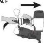
FIG. G
- Connect tool to air supply before loading fasteners, to prevent a fastener from being fired during connection. The tool driving mechanism may cycle when tool is connected to the air supply. Do not load fasteners with trigger or contact trip depressed, to prevent unintentional firing of a fastener.
- Do not remove, tamper with, or otherwise cause the tool, trigger, or contact trip to become inoperable. Do not tape or tie trigger or contact trip in the on position. Do not remove spring from contact trip. Make daily inspections for free movement of trigger and contact trip. Uncontrolled discharge could result.
- Inspect tool before use. Do not operate a tool if any portion of the tool, trigger, or contact trip is inoperable, disconnected, altered, or not working properly. Leaking air, damaged parts or missing parts should be repaired or replaced before use. (Fig. H)
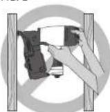
- Do not alter or modify the tool in any way. (Fig. 1)
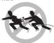
• Always assume that the tool contains fasteners. - Do not point the tool at co-workers or yourself at any time. No horseplay! Work safe! Respect the tool as a working implement. (Fig. J)
FIG. H
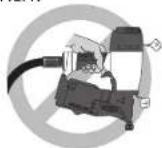
FIG. I
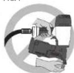
FIG. J
- Keep bystanders, children, and visitors away while operating a power tool. Distractions can cause you to lose control. When tool is not in use, it should be locked in a safe place, out of the reach of children.
- Remove finger from trigger when FIG. K
not driving fasteners. Never carry tool with finger on trigger. Accidental discharge could result. Using the trigger lock-off will prevent accidental discharge.
- Do not overreach. Maintain proper footing and balance at all times. Loss of balance may cause cause personal injury. (Fig. K)
• Make sure hose is free of obstructions or snags. Entangled or snarled hoses can cause loss of balance or footing. - Use the tool only for its intended use. Do not discharge fasteners into open air, concrete, stone, extremely hard woods, knots or any material too hard for the fastener to penetrate. Do not use the body of the tool or top cap as a hammer. Discharged fasteners may follow unexpected path and cause injury. (Fig. L)
• Always keep fingers clear of contact trip to prevent injury from inadvertent release of nails. (Fig. M)
• Refer to the Maintenance and Repairs sections for detailed information on the proper maintenance of the tool
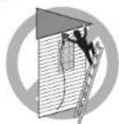
FIG. L
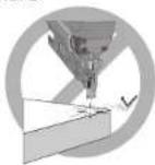
FIG. M
- Always operate the tool in a clean, lighted area. Be sure the work surface is clear of any debris and be careful not to lose footing when working in elevated environments such as rooftops.
- Do not drive fasteners near edge of material. The workpiece may split causing the fastener to ricochet, injuring you or a co-worker. Be aware that the nail may follow the grain of the wood (shiner), causing it to protrude unexpectedly from the side of the work material. Drive the nail perpendicular to the grain to reduce risk of injury. (Fig. N)
- Do not drive nails onto the heads of other fasteners or with the tool at too steep an angle. Personal injury from strong recoil, jammed fasteners, or ricocheted nails may result. (Fig. O)
- Be aware of material thickness when using the nailer. A protruding nail may cause injury.
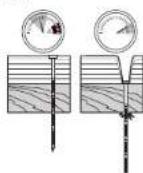
- Be aware that when the tool is being utilized at pressures on the high end of its operating range, nails can be driven completely through thin or very soft work material. Make sure the pressure in the compressor is set so that nails are set into the material and not pushed completely through. (Fig. P)
FIG. N
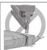
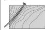
FIG. O
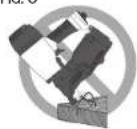
FIG. P
- Keep hands and body parts clear of immediate work area. Hold workpiece with clamps when necessary to keep hands and body out of potential harm. Be sure the workpiece is properly secured before pressing the nailer against the material. The contact trip may cause the work material to shift unexpectedly. (Fig. Q)
- Do not use tool in the presence of flammable dust, gases or fumes. The tool may produce a spark that could ignite gases causing a fire. Driving a nail into another nail may also cause a spark (Fig. R)
- Keep face and body parts away from back of the tool cap when working in restricted areas. Sudden recoil can result in impact to the body, especially when nailing into hard or dense material. (Fig. S)
- Grip tool firmly to maintain control while allowing tool to recoil away from work surface as fastener is driven. In "Contact Actuation Mode" if contact trip is allowed to recontact work surface before trigger is released an unwanted fastener will be fired.
- Choice of triggering method is important. Check the manual for triggering options.
FIG. Q
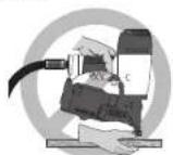
FIG. R

FIG. S
CONTACT ACTION TRIGGER
- When using the contact action trigger, be careful of unin tentional double fires resulting from tool recoil. Unwanted fasteners may be driven if the contact trip is allowed to accidentally re-contact the work surface. (Fig. T)
TO AVOID DOUBLE FIRES:
• Do not engage the tool against the work surface with a strong force.
- Allow the tool to recoil fully after each actuation.
- Use sequential action trigger.
When "contact" actuating the nailer, always keep tool in control. Inaccurate placement of tool can result in misdirected discharge of a fastener.
SEQUENTIAL ACTION TRIGGER
- When using the sequential action trigger, do not actuate the tool unless the tool is placed firmly against the workpiece.
- Do not drive nails blindly into walls, floors or other work areas. Fasteners driven into live electrical wires, plumbing, or other types of obstructions can result in injury. (Fig. U)
- Stay alert, watch what you are doing and use common sense when operating a power tool. Do not use tool while tired or under the influence of drugs, alcohol, or medication. A moment of inattention while operating power tools may result in serious personal injury.
FIG. T

FIG. U
- DEPTH ADJUSTMENT: To reduce risk of serious injury from accidental actuation when attempting to adjust depth, ALWAYS;
- Disconnect air supply
- Avoid contact with trigger during adjustments
▲ WARNING: Some dust created by power sanding, sawing, grinding, drilling, and other construction activities contains chemicals known to the State of California to cause cancer, birth defects or other reproductive harm. Some examples of these chemicals are:
- lead from lead-based paints,
• crystalline silica from bricks and cement and other masonry products, and
• arsenic and chromium from chemically-treated lumber.
Your risk from these exposures varies, depending on how often you do this type of work. To reduce your exposure to these chemicals: work in a well ventilated area, and work with approved safety equipment, such as those dust masks that are specially designed to filter out microscopic particles.
WARNING: ALWAYS USE SAFETY GLASSES. Everyday eyeglasses are NOT safety glasses. Also use face or dust mask if operation is dusty. ALWAYS WEAR CERTIFIED SAFETY EQUIPMENT:
• ANSI Z87.1 eye protection (CAN/CSA/Z94.3),
• ANSI S12.6 (S3.19) hearing protection,
• NIOSH/OSHA/MSHA respiratory protection.
SAVE ALL WARNINGS AND INSTRUCTIONS FOR FUTURE REFERENCE
Specifications
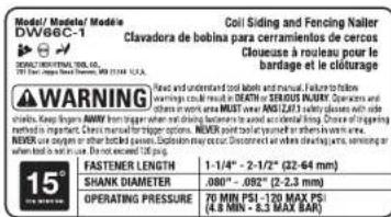
| MODEL DW66C-1 | |
| HEIGHT 11-5/8" (295.3 mm) | |
| WIDTH 4-5/8" (117.5 mm) | |
| LENGTH 10-1/2" (266.7 mm) | |
| WEIGHT 4.9 lb (2.2 kg) | |
| MAGAZINE ANGLE 15° | |
| OPERATING PRESSURE | 70 – 120 psig (4.9 – 8.43 kg/cm2) |
| AIR CONSUMPTION PER 100 CYCLES * | 3.3 cfm (.093 m2) @ 80 psi (5.62 kg/cm2) |
| LOADING CAPACITY | Up to 300–350 Nails |
| FASTENER LENGTHS 1-1/4" | -2-1/2" (531 mm - 63 mm) |
| FASTENER COLLATION 15" | plastic insert or wire weld |
*Take the actual rate at which the tool will be run to determine the amount of air required. For instance, if your fastener usage averages 50 nails per minute, you need 50% of the tool's cfm which is required to operate the tool at 100 nails per minute.
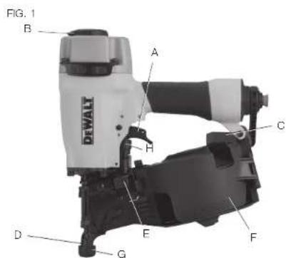
COMPONENTS (FIG. 1)
A. Trigger
E. Magazine latch
B. Exhaust
F. Magazine
C. Rafter hook
G. No-Mar pad
D. Contact trip
H. Depth adjustment dial

OPERATION
Preparing the Tool (Fig. 2, 3)
▲ WARNING: Read the section titled Important Safety Instructions at the beginning of this manual. Always wear eye and ear protection when operating this tool. Keep the nailer pointed away from yourself and others. For safe operation, complete the following procedures and checks before each use of the nailer.
- Before you use the nailer, be sure that the compressor tanks have been properly drained.
- Lubricate the tool following these directions:
a. UBEALT pneumatic tool oil or a non-detergent S.A.E. 20 weight oil. DO NOT use detergent oil or additives as they will damage o-rings and rubber parts.
b. Use a filter-regulator-lubricator in the air line between the compressor and the tool when possible.
c. If a lubricator is not available, add 5 to 10 drops of oil in the air fitting a least twice a day or every 4 hours of use.
FIG. 2
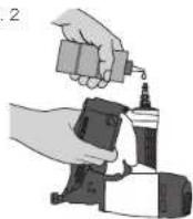
FIG. 3
- Wear proper eye, hearing and respiratory protection.
- Remove all fasteners from the magazine.
- Check for smooth and proper operation of contact trip and pusher assemblies. Do not use tool if either assembly is not functioning properly. NEVER use a tool that has the contact trip restrained in the up position.
- Check air supply. Ensure that air pressure does not exceed recommended operating limits, refer to Tool Specifications.
- Connect air hose.
- Check for audible leaks around valves and gaskets. Never use a tool that leaks or has damaged parts.
▲WARNING: To reduce the risk of personal injury, disconnect tool from air supply before performing maintenance, clearing a jammed fastener, leaving work area, moving tool to another location or handling the tool to another person.
Trigger
▲WARNING: Always wear proper eye [ANSI Z87.1 (CAN/CSA Z94.3)] and hearing protection [ANSI S12.6 (S3.19)] when operating this tool.
▲WARNING: The operator must not hold the trigger pulled on contact trip tools except during fastening operation, as serious injury could result if the trip accidentally contacted someone or something, causing the tool to cycle.
WARNING: Keep hands and body away from the discharge area of the tool. A contact trip tool may bounce from the recoil of driving a fastener and an unwanted second fastener may be driven, possibly causing injury.
▲WARNING: Never use rafter hook to hang tool from body, clothing or belt.
CONTACT TRIP (BLACK TRIGGER)
The common operating procedure on "Contact Trip" tools is for the operator to contact the work to actuate the trip mechanism while keeping the trigger pulled, thus driving a fastener each time the work is contacted. This will allow rapid fastener placement on many jobs, such as sheathing, decking and pallet assembly. All pneumatic tools are subject to recoil when driving fasteners. The tool may bounce, releasing the trip, and if unintentionally allowed to recontact the work surface with the trigger still actuated (finger still holding trigger pulled) an unwanted second fastener will be driven.
SEQUENTIAL TRIP (GRAY TRIGGER)
The Sequential Trip requires the operator to hold the tool against the work before pulling the trigger. This makes accurate fastener placement easier, for instance on framing, toe nailing and crating applications.
The Sequential Trip allows exact fastener location without the possibility of driving a second fastener on recoil, as described under Contact Trip.
The Sequential Trip Tool has a positive safety advantage because it will not accidentally drive a fastener if the tool is contacted against the work – or anything else – while the operator is holding the trigger pulled.
When using the contact trip (black) trigger the tool contains a contact trip that operates in conjunction with the trigger to drive a fastener. There are two methods of operation to drive fasteners with a contact trip tool.
SINGLE FASTENER PLACEMENT: To operate the tool in this manner, first position the contact trip on the work surface, WITHOUT PULLING THE TRIGGER. Depress the contact trip until the nose touches the work surface and then pull the trigger to drive a fastener. Do not press the tool against the work with extra force. Instead, allow the tool to recoil off the work surface to avoid a second unwanted fastener. Remove your finger from the trigger after each operation.
RAPID FASTENER OPERATION: To operate the tool in this manner, hold the tool with the contact trip pointing towards but not touching the work surface. Pull the trigger and then tap the contact trip against the work surface using a bouncing motion. Each depression of the contact trip will cause a fastener to be driven.
When using the sequential trip (gray) trigger the tool contains a contact trip that operates in conjunction with the trigger to drive a fastener. To operate a sequential trip tool, first position the contact trip on the work surface
WITHOUT PULLING THE TRIGGER, Depress the contact trip and then pull the trigger to drive a fastener. As long as the contact trip is contacting the work and is held depressed, the tool will drive a fastener each time the trigger is depressed. If the contact trip is allowed to leave the work surface, the sequence described above must be repeated to drive another fastener.
Tool Operation Check (Fig.1)
⚠ WARNING: Remove all fasteners from tool before performing tool operation check.
A. With finger off the trigger (A), press the contact trip against the work surface.
THE TOOL MUST NOT CYCLE.
B. Hold the tool off the work surface, and pull the trigger.
THE TOOL MUST NOT CYCLE.
C. With the tool off the work surface, pull the trigger. Press the contact trip against the work surface.
THE TOOL MUST CYCLE.
D. Without touching the trigger, press the contact trip against the work surface, then pull the trigger.
THE TOOL MUST CYCLE.
A. Press the contact trip against the work surface, without touching the trigger.
THE TOOL MUST NOT CYCLE.
B. Hold the tool off the work surface and pull the trigger.
THE TOOL MUST NOT CYCLE.
Release the trigger. The trigger must return to the trigger stop on the frame.
C. Pull the trigger and press the contact trip against the work surface.
THE TOOL MUST NOT CYCLE.
D. With finger off the trigger, press the contact trip against the work surface. Pull the trigger.
THE TOOL MUST CYCLE.
Loading the Tool (Fig. 1, 4-7)
⚠ WARNING: Keep tool pointed in a safe direction when loading nails.
⚠ WARNING: Never load nails with the contact trip or trigger activated.
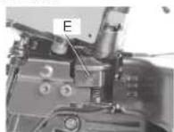
- Open the magazine (F). Pull down magazine latch (E) and swing door/magazine cover outward. Refer to Figure 4.
FIG. 4 FIG. 5
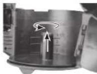
- The nailer must be set for the length of nail to be used. Nails will not feed smoothly if the magazine is not correctly adjusted. The magazine contains an adjustable nail platform on which the nail coil rests. The nail platform can be moved up and down to three nail settings.
To change setting pull up on the post and twist to the correct step Refer to Figure 5.
| 1-1/4" - 1-1/2" (32-38 mm) nails upper step |
| 1-3/4" - 2" (45-50 mm) nails middle step |
| 2-1/4" - 2-1/2" (57-64 mm) nails bottom step |
- Load the coil of nails, refer to Tool Specifications to determine appropriate fastener.
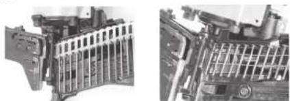
Place the coil of nails over the post in the magazine. Uncoil enough nails to reach the feed pawl. Place the first nail in front of the front tooth on the feed pawl, in the driver channel. The nail heads must be in the slot in the nose. Refer to Figure 6.
FIG. 6
natural_image
Close-up of mechanical components with no visible text or symbolsPLASTIC INSERT WIRE WELD
-
Swing cover closed. To aid in the feeding of plastic collated nails the tab on the cover should be repositioned. To do so apply pressure to the top center of the tab and simultaneously apply pressure to the bottom outer edge of the tab until it rests on the top outer brim of the cover. Swing the door/magazine cover closed. Check that the latch engages when released. (If it does not engage, check that the nail heads are in the slot in the nose.)
-
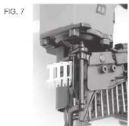
Removal of plastic strip. As nails are driven, the plastic strip will feed out of the tool. When sufficient strip has been fed out, it can be torn away by pulling against the tear edge in the nose. Refer to Figure 7.
natural_image
Mechanical assembly diagram showing a motor or actuator with no visible text or symbolsDepth Setting (Fig. 1)
▲WARNING: Disconnect air line from tool and remove fasteners from magazine before making adjustments or personal injury may result.
The fastener depth control adjustment feature provides control of the nail drive depth from flush with or just above the work surface to shallow or deep countersink. Rotate depth control adjustment wheel (H) to give the desired depth of drive.
Rafter Hook (Fig. 1)
The integrated rafter hook (C) can be rotated to either side of the tool to accommodate left- or right-handed users.
NOTE: The rafter hook can not be removed.
Cold Weather Operation
▲WARNING: Read the section titled Important Safety Instructions at the beginning of this manual. Always wear eye and ear protection when operating this tool. Keep the nailer pointed away from yourself and others. For safe operation, complete the following procedures and checks before each use of the nailer.
When operating tools at temperatures below freezing, complete preparation procedures outlined above and follow the directions below.
- Make sure compressor tanks have been properly drained prior to use. Always drain the compressor tanks at least once daily while using the nailer. This is especially important in cold weather because any moisture in the air in the tanks will condense in the cold temperature.
- Keep the tool as warm as possible prior to use.
- Put 5 to 10 drops of DEWALT Pneumatic Tool Oil or winter weight pneumatic oil containing ethylene glycol in the end cap.
- Lower air pressure to 80 psi or less.
- Actuate the tool 5 or 6 times into scrap lumber to lubricate o-rings.
-
Turn pressure up to operating level (not to exceed 120 psi) and use tool as normal.
-
Re-lubricate with DEWALT Pneumatic Tool Oil or winter weight pneumatic oil containing ethylene glycol in the end cap at least twice a day or after 4 hours of use.
Hot Weather Operation
Tool should operate normally. However, keep tool out of direct sunlight as excessive heat can damage bumpers, o-rings and other rubber parts.
MAINTENANCE
⚠ WARNING: Disconnect air line from tool and remove fasteners from magazine before making adjustments or personal injury may result.
Daily Maintenance Chart
ACTION Lubricate tool with 5-10 drops of DEWALT Pneumatic Tool Oil
WHY Prevents failure of o-rings
HOW Insert drops into air fitting on end cap of tool
ACTION Drain compressor tanks and hoses daily
WHY Prevents accumulation of moisture in compressor and nailer
HOW Open petcocks or other drain valves on compressor tanks. Allow any accumulated water to drain from hoses
ACTION Clean magazine, pusher, and contact trip mechanism
WHY Permits smooth operation, reduces wear, and prevents jams
HOW Blow clean with compressed air. The use of oils or solvents is not recommended as they tend to attract debris
ACTION Before each use, check to ensure all screws, nuts and fasteners are tight and undamaged
WHY Prevents jams, leaks and premature failure of tool parts
HOW Tighten loose screws or other fasteners using the appropriate hex wrench or screwdriver
Cleaning
▲ WARNING: Blow dirt and dust out of all air vents with clean, dry air at least once a week. To minimize the risk of eye injury, always wear ANSI Z87.1 approved eye protection when performing this.
▲WARNING: Never use solvents or other harsh chemicals for cleaning the non-metallic parts of the tool. These chemicals may weaken the plastic materials used in these parts. Use a cloth dampened only with water and mild soap. Never let any liquid get inside the tool; never immerse any part of the tool into a liquid.
Repairs
⚠WARNING: To reduce the risk of serious personal injury, remove nails from magazine before making any adjustments or servicing this tool.
Refer to the Troubleshooting Guide at the end of this section. To assure product SAFETY and RELIABILITY, repairs, maintenance and adjustment should be performed by a DeWalt factory service center, a DeWalt authorized service center or other qualified service personnel. Always use identical replacement parts.
Accessories
WARNING: Since accessories, other than those offered by DeWALT, have not been tested with this product, use of such accessories with this tool could be hazardous. To reduce the risk of injury, only DeWALT, recommended accessories should be used with this product.
Recommended accessories for use with your tool are available at extra cost from your local dealer or authorized service center. If you need assistance in locating any accessory, please contact DEWALT Industrial Tool Co., 701 East Joppa Road, Towson, MD 21286; call 1-800-4-DEWALT (1-800-433-9258) or visit our website www.dewalt.com.
Register Online
Thank you for your purchase. Register your product now for:
- WARRANTY SERVICE: Registering your product will help you obtain more efficient warranty service in case there is a problem with your product.
- CONFIRMATION OF OWNERSHIP: In case of an insurance loss, such as fire, flood or theft, your registration of ownership will serve as your proof of purchase.
- FOR YOUR SAFETY: Registering your product will allow us to contact you in the unlikely event a safety notification is required under the Consumer Product Safety Act.
Register online at www.dewalt.com/register.
Seven Year Limited Warranty
DEWALT will repair, without charge, any defects due to faulty materials or workmanship for seven years from the date of purchase. This warranty does not cover part failure due to normal wear or tool abuse. For further detail of warranty coverage and warranty repair information, visit www.dewalt.com or call 1-800-4-DEWALT (1-800-433-9258). This warranty does not apply to accessories or damage caused where repairs have been made or attempted by others. This warranty gives you specific legal rights and you may have other rights which vary in certain states or provinces.
In addition to the warranty, DEWALT tools are covered by our:
1 YEAR FREE SERVICE
DEFWALT will maintain the tool and replace worn parts caused by normal use, for free, any time during the first year after purchase. Nailer wear items, such as o-rings and driver blades, are not covered.
90 DAY MONEY BACK GUARANTEE
If you are not completely satisfied with the performance of your DEWALT Power Tool, Laser, or Nailer for any reason, you can return it within 90 days from the date of purchase with a receipt for a full refund – no questions asked.
LATIN AMERICA: This warranty does not apply to products sold in Latin America. For products sold in Latin America, see country specific warranty information contained in the packaging, call the local company or see website for warranty information.
FREE WARNING LABEL REPLACEMENT: If your warning labels become illegible or are missing, call 1-800-4-DEWALT (1-800-433-9258) for a free replacement.
TROUBLESHOOTING GUIDE
MANY COMMON PROBLEMS CAN BE SOLVED EASILY BY UTILIZING THE CHART BELOW.
FOR MORE SERIOUS OR PERSISTENT PROBLEMS, CONTACT A DEWALT SERVICE CENTER OR CALL 1-(800)-4-DEWALT.
▲WARNING: To reduce the risk of serious personal injury, remove
fasteners from magazine before making any adjustments or servicing this tool.
| SYMPTOM CAUSE FIX | ||
| Trigger valve housing leaks air O-ring cut or cracked Replace O-ring | ||
| Trigger valve stem leaks air O-ring/seals cut or cracked Replace trigger valve assembly | ||
| Frame/nose leaks air Loose nose screws Tighten and recheck | ||
| O-ring or Gasket is cut or cracked Replace O-ring or gasket | ||
| Bumper cracked/worn Replace bumper | ||
| Frame/cap leaks air Damaged gasket or seal Replace gasket or seal | ||
| Cracked/worn head valve bumper Replace bumper | ||
| Loose cap screws | Tighten and recheck | |
| Failure to cycle | Air supply restriction | Check air supply equipment |
| Tool dry, lack of lubrication | Use DcWALT pneumatic tool oil | |
| Worn head valve O-rings | Replace O-rings | |
| Broken cylinder cap spring Replace cylinder cap spring | ||
| Head valve stuck in cap | Disassemble/Check/Lubricate | |
| Lack of power; slow to cycle | Tool dry, lacks lubrication | Use DcWALT pneumatic tool oil |
| Broken cylinder cap spring Replace cap spring | ||
| O-rings/seals cut or cracked | Replace O-rings/seals | |
| Exhaust blocked | Check bumper, head valve spring, muffler | |
| Trigger assembly worn/seals | Replace trigger assembly | |
| Dirt/tar build up on driver | Disassemble nose/driver to clean | |
| Cylinder sleeve not seated correctly on bottom bumper | Disassemble to correct | |
| Head valve dry | Disassemble/lubricate | |
| Air pressure too low | Check air supply equipment | |
TROUBLESHOOTING GUIDE
MANY COMMON PROBLEMS CAN BE SOLVED EASILY BY UTILIZING THE CHART BELOW.
FOR MORE SERIOUS OR PERSISTENT PROBLEMS, CONTACT A DEWALT SERVICE CENTER OR CALL 1-(800)-4-DEWALT.
⚠ WARNING: To reduce the risk of serious personal injury, remove
fasteners from magazine before making any adjustments or servicing this tool.
| SYMPTOM CAUSE FIX | ||
| Skipping fasteners; intermittent feed | Worn bumper Replace bumper | |
| Tar/dirt in driver channel Disassemble and clean nose and driver | ||
| Air restriction/inadequate air flow through quick disconnect socket and plug | Replace quick disconnect fittings | |
| Worn piston O-ring Replace O-ring, check driver | ||
| Tool dry, lacks lubrication Use | DLWALT pneumatic tool oil | |
| Damaged feed piston spring Replace spring | ||
| Low air pressure Check air supply system to tool | ||
| Loose canister nose screws Tighten all screws | ||
| Fasteners too short for tool Use only recommended fasteners | ||
| Bent fasteners Discontinue using those fasteners | ||
| Wrong size fasteners Use only recommended fasteners | ||
| Leaking head cap gasket | Tighten screws/replace gasket | |
| Trigger valve O-ring cut/worn | Replace O-ring | |
| Broken/chipped driver | Replace driver (check piston O-ring) | |
| Dry/dirty magazine | Clean magazine | |
| Fasteners jam in tool | Driver channel worn | Replace nose/check door |
| Wrong size fasteners Use only recommended fasteners | ||
| Bent fasteners Discontinue using these fasteners | ||
| Loose canister/nose screws Tighten all screws | ||
| Broken/chipped driver | Replace driver | |
TROUBLESHOOTING GUIDE
MANY COMMON PROBLEMS CAN BE SOLVED EASILY BY UTILIZING THE CHART BELOW.
FOR MORE SERIOUS OR PERSISTENT PROBLEMS, CONTACT A DEWALT SERVICE CENTER OR CALL 1-(800)-4-DEWALT.
⚠ WARNING: To reduce the risk of serious personal injury, remove
fasteners from magazine before making any adjustments or servicing this tool
| SYMPTOM CAUSE FIX | ||
| COIL NAILERS | ||
| Skipping fasteners; intermittent feed | Feed piston dry Add | DEWALT pneumatic tool oil in hole in feed piston cover |
| Feed piston O-rings cracked/wom Replace O-rings/check bumper and spring. Lubricate assembly | ||
| Check pawl binding Inspect pawl and spring on door. Must work freely | ||
| Canister bottom not set correctly Set canister bottom for length of nails being used | ||
| Broken weld wires in nail coil Remove coil of nails and use another coil | ||
| Fasteners jam in tool/canister Wrong | size fasteners for tool Use only recommended fasteners/check canister bottom adjustment | |
| Broken welded wires in nail coil Remove coil of nails and use another coil | ||
AVANT DE FAIRE FONCTIONNER CET OUTIL, LIRE ATTENTIVEMENT ET COMPRENDRE TOUTES LES DIRECTIVES DE LA SECTION "CONSIGNES DE SÉCURITÉ IMPORTANTES"
natural_image
Diagram showing a hand operating a tool to cut wood grain, with a close-up view of the same material (no text or symbols present)FIG. O
FIG. P
natural_image
Close-up of a mechanical assembly with no visible text or symbolsRéglage de la profondeur (fi g. 1)
GUIDE DE DÉPANNAGE
IL EST POSSIBLE DE RÉSOUDRE FACILEMENT LES PROBLÈMES LES PLUS COMMUNS À L'AIDE DU TABLEAU CI-DESSOUS. POUR DES PROBLÈMES PLUS GRAVES OU DES PROBLÈMES QUI PERSISTENT, COMMUNIQUER AVEC UN CENTRE DE RÉPARATION DEWALT OU COMPOSER LE 1 800 4-DEWALT.
FUNCIONAMIENTO
natural_image
Close-up of mechanical components with no visible text or symbolsnatural_image
Mechanical assembly diagram showing internal components and mounting brackets (no text or labels)
Compressor will be sufficient for tools at all production rates.
Compressor will be sufficient at slow or moderate production rates, but may have difficulty at very rapid rates.
Compressor will be adequate only when tools are utilized at slow production rates, (punch-out or occasional use)
DEWALT Industrial Tool Co., 701 East Joppa Road, Towson, MD 21286
(NOV14) Part No. 9R208252
DW66C-1 Copyright © 2014 DEWALT
The following are trademarks for one or more DEWALT power tools: the yellow and black color scheme; the "D" shaped air intake grill; the array of pyramids on the handgrip; the kit box configuration; and the array of lozenge-shaped humps on the surface of the tool.