
C 3607DRA - Saw METABO - Free user manual and instructions
Find the device manual for free C 3607DRA METABO in PDF.

User questions about C 3607DRA METABO
0 question about this device. Answer the ones you know or ask your own.
Ask a new question about this device
Download the instructions for your Saw in PDF format for free! Find your manual C 3607DRA - METABO and take your electronic device back in hand. On this page are published all the documents necessary for the use of your device. C 3607DRA by METABO.
USER MANUAL C 3607DRA METABO
(Laser Marker Equipment)
Cordless Slide Compound Miter Saw
natural_image
Technical line drawing of a mechanical cutting machine (no text or symbols)SAFETY INSTRUCTIONS AND INSTRUCTION MANUAL

WARNING
IMPROPER OR UNSAFE use of this power tool can result in death or serious bodily injury!
This manual contains important information about product safety. Please read and understand this manual before operating the power tool. Please keep this manual available for other users and owners before they use the power tool. This manual should be stored in safe place.
INSTRUCTIONS DE SECURITE ET MODE D'EMPLOI

AVERTISSEMENT
IMPORTANT SAFETY INFORMATION
Read and understand all of the safety precautions, warnings and operating instructions in the Instruction Manual before operating or maintaining this power tool.
Most accidents that result from power tool operation and maintenance are caused by the failure to observe basic safety rules or precautions. An accident can often be avoided by recognizing a potentially hazardous situation before it occurs, and by observing appropriate safety procedures.
Basic safety precautions are outlined in the "SAFETY" section of this Instruction Manual and in the sections which contain the operation and maintenance instructions.
Hazards that must be avoided to prevent bodily injury or machine damage are identified by WARNINGS on the power tool and in this Instruction Manual.
NEVER use this power tool in a manner that has not been specifically recommended by metabo HPT.
MEANINGS OF SIGNAL WORDS
WARNING indicates a potentially hazardous situations which, if ignored, could result in death or serious injury.
CAUTION indicates a potentially hazardous situations which, if not avoided, may result in minor or moderate injury, or may cause machine damage.
NOTE emphasizes essential information.
MEANINGS OF SYMBOLS
| SymbolsThe following show symbols used for the machine. Be sure that you understand their meaning before use. | |||
 | ⚠ WARNINGTo reduce the risk of injury, user must read instruction manual. | ⚠ WARNINGAlways wear eye protection. | |
 | ⚠ CAUTIONDo not stare at operating lamp. | ⚠ WARNINGAlways wear hearing protection. | |
SAFETY
GENERAL POWER TOOL SAFETY WARNINGS

WARNING
Read all safety warnings, instructions, illustrations and specifications provided with this power tool.
Failure to follow all instructions listed below may result in electric shock, fire and/or serious injury.
Save all warnings and instructions for future reference.
The term “power tool” in the warnings refers to your mains-operated (corded) power tool or battery-operated (cordless) power tool.
1) Work area safety
a) Keep work area clean and well lit.
Cluttered or dark areas invite accidents.
b) Do not operate power tools in explosive atmospheres, such as in the presence of fl ammable liquids, gases or dust.
Power tools create sparks which may ignite the dust or fumes.
c) Keep children and bystanders away while operating a power tool.
Distractions can cause you to lose control.
2) Electrical safety
a) Power tool plugs must match the outlet.
Never modify the plug in any way.
Do not use any adapter plugs with earthed (grounded) power tools.
Unmodified plugs and matching outlets will reduce risk of electric shock.
b) Avoid body contact with earthed or grounded surfaces, such as pipes, radiators, ranges and refrigerators.
There is an increased risk of electric shock if your body is earthed or grounded.
c) Do not expose power tools to rain or wet conditions.
Water entering a power tool will increase the risk of electric shock.
d) Do not abuse the cord. Never use the cord for carrying, pulling or unplugging the power tool.
Keep cord away from heat, oil, sharp edges or moving parts.
Damaged or entangled cords increase the risk of electric shock.
e) When operating a power tool outdoors, use an extension cord suitable for outdoor use.
Use of a cord suitable for outdoor use reduces the risk of electric shock.
f) If operating a power tool in a damp location is unavoidable, use a residual current device (RCD) protected supply.
Use of an RCD reduces the risk of electric shock.
3) Personal safety
a) Stay alert, watch what you are doing and use common sense when operating a power tool. Do not use a power tool while you are tired or under the influence of drugs, alcohol or medication.
A moment of inattention while operating power tools may result in serious personal injury.
b) Use personal protective equipment. Always wear eye protection.
Protective equipment such as dust mask, non-skid safety shoes, hard hat, or hearing protection used for appropriate conditions will reduce personal injuries.
c) Prevent unintentional starting. Ensure the switch is in the off -position before connecting to power source and/or battery pack, picking up or carrying the tool.
Carrying power tools with your finger on the switch or energising power tools that have the switch on invites accidents.
d) Remove any adjusting key or wrench before turning the power tool on.
A wrench or a key left attached to a rotating part of the power tool may result in personal injury.
e) Do not overreach. Keep proper footing and balance at all times.
This enables better control of the power tool in unexpected situations.
f) Dress properly. Do not wear loose clothing or jewellery. Keep your hair, clothing and gloves away from moving parts.
Loose clothes, jewellery or long hair can be caught in moving parts.
g) If devices are provided for the connection of dust extraction and collection facilities, ensure these are connected and properly used.
Use of dust collection can reduce dust-related hazards.
h) Do not let familiarity gained from frequent use of tools allow you to become complacent and ignore tool safety principles.
A careless action can cause severe injury within a fraction of a second.
4) Power tool use and care
a) Do not force the power tool. Use the correct power tool for your application.
The correct power tool will do the job better and safer at the rate for which it was designed.
b) Do not use the power tool if the switch does not turn it on and off.
Any power tool that cannot be controlled with the switch is dangerous and must be repaired.
c) Disconnect the plug from the power source and/or remove the battery pack, if detachable, from the power tool before making any adjustments, changing accessories, or storing power tools.
Such preventive safety measures reduce the risk of starting the power tool accidentally.
d) Store idle power tools out of the reach of children and do not allow persons unfamiliar with the power tool or these instructions to operate the power tool.
Power tools are dangerous in the hands of untrained users.
e) Maintain power tools and accessories. Check for misalignment or binding of moving parts, breakage of parts and any other condition that may affect the power tool's operation. If damaged, have the power tool repaired before use.
Many accidents are caused by poorly maintained power tools.
f) Keep cutting tools sharp and clean.
Properly maintained cutting tools with sharp cutting edges are less likely to bind and are easier to control.
g) Use the power tool, accessories and tool bits etc. in accordance with these instructions, taking into account the working conditions and the work to be performed.
Use of the power tool for operations different from those intended could result in a hazardous situation.
h) Keep handles and grasping surfaces dry, clean and free from oil and grease.
Slippery handles and grasping surfaces do not allow for safe handling and control of the tool in unexpected situations.
5) Battery tool use and care
a) Recharge only with the charger specified by the manufacturer.
A charger that is suitable for one type of battery pack may create a risk of fire when used another battery pack.
b) Use power tools only with specifically designated battery packs.
Use of any other battery packs may create a risk of injury and fire.
c) When battery pack is not in use, keep it away from other metal objects, like paper clips, coins, keys, nails, screws or other small metal objects, that can make a connection from one terminal to another.
Shorting the battery terminals together may cause burns or a fire.
d) Under abusive conditions, liquid may be ejected from the battery; avoid contact. If contact accidentally occurs, fl ush with water. If liquid contacts eyes, additionally seek medical help.
Liquid ejected from the battery may cause irritation or burns.
e) Do not use a battery pack or tool that is damaged or modified.
Damaged or modified batteries may exhibit unpredictable behaviour resulting in fire, explosion or risk of injury.
f) Do not expose a battery pack or tool to fire or excessive temperature.
Exposure to fire or temperature above 265^ F ( 130^ C) may cause explosion.
g) Follow all charging instructions and do not charge the battery pack or tool outside the temperature range specified in the instructions.
Charging improperly or at temperatures outside the specified range may damage the battery and increase the risk of fire.
6) Service
a) Have your power tool serviced by a qualified repair person using only identical replacement parts.
This will ensure that the safety of the power tool is maintained.
b) Never service damaged battery packs.
Service of battery packs should only be performed by the manufacturer or authorized service providers.
PRECAUTION
Keep children and infirm persons away.
When not in use, tools should be stored out of reach of children and infirm persons.
SAFETY INSTRUCTIONS FOR MITER SAW with
a) Miter saws are intended to cut wood or wood-like products, they cannot be used with abrasive cut-off wheels for cutting ferrous material such as bars, rods, studs, etc.
Abrasive dust causes moving parts such as the lower guard to jam. Sparks from abrasive cutting will burn the lower guard, the kerf insert and other plastic parts.
b) Use clamps to support the workpiece whenever possible. If supporting the workpiece by hand, you must always keep your hand at le mm from either side of the saw blade. Do not use this saw to cut pieces that are too small to be securely clamped or held by hand.
If your hand is placed too close to the saw blade, there is an increased risk of injury from blade contact.
c) The workpiece must be stationary and clamped or held against both the fence and the table. Do not feed the workpiece into the blade or cut "freehand" in any way.
Unrestrained or moving workpieces could be thrown at high speeds, causing injury.
d) Push the saw through the workpiece. Do not pull the saw through the workpiece. To make a cut, raise the saw head and pull it out over the workpiece without cutting, start the motor, press the saw head down and push the saw through the workpiece.
Cutting on the pull stroke is likely to cause the saw blade to climb on top of the workpiece and violently throw the blade assembly towards the operator.
e) Never cross your hand over the intended line of cutting either in front or behind the saw blade.
Supporting the workpiece “cross handed” i.e. holding the workpiece to the right of the saw blade with your left hand or vice versa is very dangerous.
f) Do not reach behind the fence with either hand closer than 100 mm from either side of the saw blade, to remove wood scraps, or for any other reason while the blade is spinning.
The proximity of the spinning saw blade to your hand may not be obvious and you may be seriously injured.
g) Inspect your workpiece before cutting. If the workpiece is bowed or warped, clamp it with the outside bowed face toward the fence. Always make certain that there is no gap between the workpiece, fence and table along the line of the cut.
Bent or warped workpieces can twist or shift and may cause binding on tile spinning saw blade while cutting. There should be no nails or foreign objects in the workpiece.
h) Do not use the saw until the table is clear of all tools, wood scraps, etc., except for the workpiece.
Small debris or loose pieces of wood or other objects that contact the revolving blade can be thrown with high speed.
i) Cut only one workpiece at a time.
Stacked multiple workpieces cannot be adequately clamped or braced and may bind on the blade or shift during cutting.
j) Ensure the miter saw is mounted or placed on a level, fi rm work surface before use.
A level and firm work surface reduces the risk of the miter saw becoming unstable.
k) Plan your work. Every time you change the bevel or miter angle setting, make sure the adjustable fence is set correctly to support the workpiece and will not interfere with the blade or the guarding system.
Without turning the tool "ON" and with no workpiece on the table, move the saw blade through a complete simulated cut to assure there will be no interference or danger of cutting the fence.
I) Provide adequate support such as table extensions, saw horses, etc. for a workpiece that is wider or longer than the table top.
Workpieces longer or wider than the miter saw table can tip if not securely supported. If the cut-off piece or workpiece tips, it can lift the lower guard or be thrown by the spinning blade.
m) Do not use another person as a substitute for a table extension or as additional support.
Unstable support for the workpiece can cause the blade to bind or the workpiece to shift during the cutting operation pulling you and the helper into the spinning blade.
n) The cut-off piece must not be jammed or pressed by any means against the spinning saw blade. If confined, i.e. using length stops, the cut-off piece could get wedged against the blade and thrown violently.
o) Always use a clamp or a fixture designed to properly support round material such as rods or tubing.
Rods have a tendency to roll while being cut, causing the blade to "bite" and pull the work with your hand into the blade.
p) Let the blade reach full speed before contacting the workpiece.
This will reduce the risk of the workpiece being thrown.
q) If the workpiece or blade becomes jammed, turn the miter saw off. Wait for all moving parts to stop and disconnect the plug from the power source and/or remove the battery pack. Then work to free the jammed material.
Continued sawing with a jammed workpiece could cause loss of control or damage to the miter saw.
r) After finishing the cut, release the switch, hold the saw head down and wait for the blade to stop before removing the cut-off piece.
Reaching with your hand near the coasting blade is dangerous.
s) Hold the handle firmly when making an incomplete cut or when releasing the switch before the saw head is completely in the down position.
The braking action of the saw may cause the saw head to be suddenly pulled downward, causing a risk of injury.
SPECIFIC SAFETY RULES FOR USE OF THIS POWER TOOL AND SYMBOLS
WARNING
The following specific operating instructions must be observed when using this POWER TOOL in order to avoid injury:
DO's
ALWAYS OBSERVE THE FOLLOWING RULES TO ASSURE SAFE USE OF THIS TOOL:
-
Review this Manual and familiarize yourself with the safety rules and operating instructions for this POWER TOOL before attempting to use it.
-
Remove all packing materials attached or connected to the tool before attempting to operate it.
-
Always confirm that the POWER TOOL is clean before using it.
-
Always wear snug-fitting clothing, non-skid footwear (preferably with steel toes) and eye protection when operating the POWER TOOL.
-
Always handle the POWER TOOL carefully. If the POWER TOOL falls or strikes against a hard object, it might become deformed or cracked or sustain other damage.
-
Always cease operating the saw at once, if you notice any abnormality whatsoever.
-
Always confirm that all components are mounted properly and securely before using the tool.
-
When replacing the saw blade, always confirm that the rpm rating of the new blade is correct for use on this tool.
- Always shut off the power and wait for the saw blade to completely stop rotating before doing any maintenance or adjustments.
- During slide cutting, always push the saw blade away from the operator.
- Always clamp or otherwise secure the workpiece to the fence; otherwise the workpiece might be thrust form the table and cause bodily harm.
- During miter or bevel cutting, always wait for the rotation of the blade to stop completely before the saw blade.
- Always make a trial run first before attempting any new use of the saw.
- Always handle the saw blade with care when dismounting and mounting it.
- Always confirm that the workpiece is free of nails or other foreign objects before beginning a cut.
- Always keep your hands out of the path of the saw blade.
- Always confirm that the lower guard is in the proper place before using the saw.
- Always confirm that the lower guard does not obstruct the sliding motion of the saw before attempting slide cutting.
- Always confirm that the motor air vents are fully open before using the tool.
- Always wait until the motor has reached full speed before starting a cut.
- Always keep the handles dry, clean and free of oil and grease. Hold the tool firmly when in use.
- Always use outboard stands to provide support for long workpieces that overhang the table of the slide compound miter saw.
- Always operate the tool after ensuring the workpiece is fixed properly with a vise assembly.
- The operating instructions provided with the tool shall direct the user to secure the tool to supporting structure if, during normal operation, there is a tendency for the tool to tip over, slide, or walk on the supporting surface.
- Ensure before each cut that the machine is stable.
- If the saw blade should become jammed, switch the machine off and hold the workpiece until the saw blade comes to a complete stop. To prevent kickback, the workpiece may not be moved until after the machine has come to a complete stop.
Correct the cause for the jamming of the saw blade before restarting the machine. -
Use only saw blades that are marked with a maximum permitted speed equal or higher than the no-load speed marked on the POWER TOOL.
-
Use only a saw blade diameter in accordance with the markings on the POWER TOOL.
-
Replace the table insert when worn.
DON'Ts
NEVER VIOLATE THE FOLLOWING RULES TO ASSURE SAFE USE OF THIS TOOL:
- Never operate the POWER TOOL unless you fully understand the operating instructions contained in this Manual.
- Never leave tool running unattended. Turn power off. Don't leave tool until it comes to a complete stop.
Lifting Never operate the POWER TOOL when you are tired, after you have taken any medications, or have consumed any alcoholic beverages.
4. Never use the POWER TOOL for applications not specified in the instruction manual.
5. Never operate the tool while wearing loose clothing, a necktie or jewelry, or while your hair is uncovered, to protect against getting caught in the moving machinery.
6. Never reach around the saw blade.
7. Never touch any moving parts, including the blade, while the saw is in use.
8. Never remove any safety devices or blade guards; use of the tool without them would be hazardous.
9. Never lock the lower guard; always confirm that it slides smoothly before using the tool.
10. Never attempt to move a plugged-in POWER TOOL while your finger is on the starting switch.
11. Never use the POWER TOOL if the starting switch does not turn on and off properly.
12. Never use the POWER TOOL if the plastic housing or the handle is cracked or deformed.
13. Never use the POWER TOOL near flammable liquids or gases because sparking can cause an explosion.
14. Never clean plastic components with solvents because the plastic may dissolve.
15. Never operate the saw unless all the blade guards are in place.
16. Never raise the saw blade from the workpiece until it has first come to a complete stop.
17. When slide cutting, never pull the handle toward the operator, since this could cause the saw blade to kick up from the workpiece. Always push the handle away from the operator in a single, smooth motion.
18. Never place your limbs inside of the line next to warning sign " 🔍" while the tool is being operated. This may cause hazardous conditions.
19. Never use abrasive type blades on this saw.
20. Never expose to rain or use in damp locations.
21. Never cut ferrous metals or masonry.
22. Do not replace the laser with a different type.
- Do not stand in a line with the saw blade In front of the machine. Always stand aside of the saw blade. This protects your body against possible kickback. Keep hands, fingers and arms away from the rotating saw blade.
- Do not cross your arms when operating the tool arm.
- Definitions for symbols used on this tool.
V ......volts
A ......amperes
Hz .....hertz
W ......watts
or DC .....direct current
\~ or AC .....alternating current
no ......no load speed
---/min ....revolutions or reciprocation per minute min ....minutes
- Do not use the product if the tool or the battery terminals (battery mount) are deformed.
Installing the battery could cause a short circuit that could result in smoke emission or ignition. - Keep the tool's terminals (battery mount) free of swarf and dust.
○ Prior to use, make sure that swarf and dust have not collected in the area of the terminals.
During use, try to avoid swarf or dust on the tool from falling on the battery.
When suspending operation or after use, do not leave the tool in an area where it may be exposed to falling swarf or dust.
Doing so could cause a short circuit that could result in smoke emission or ignition.

WARNING
- Always wear eye protection when using the slide compound miter saw.
- Always keep hands out of the path of the saw blade.
- Never operate the saw without the guards in place.
- Never perform any freehand operation with the slide compound miter saw.
- Never reach around the saw blade.
- Always turn off tool and wait for saw blade to stop before moving workpiece or changing settings.
- Always disconnect the battery before changing blade or servicing.
- Saw blade diameter is 7-1/4" (185 mm).
- No load speed is 4,000/min.
- To reduce the risk of injury, return carriage to the full rear position after each crosscut operation.
REPLACEMENT PARTS
When servicing use only identical replacement parts. Repairs should be conducted only by a metabo HPT authorized service center.
IMPORTANT SAFETY INSTRUCTIONS FOR CHARGER OR ADAPTER
The term "charger or adapter" in the safety instructions refers to your battery charger or AC/DC adapter.

WARNING
Death or serious bodily injury could result from improper or unsafe use of charger or adapter. To avoid these risks, follow these basic safety instructions:
READ ALL INSTRUCTIONS
- This manual contains important safety and operating instructions for battery charger Model UC18YSL3 or AC/DC adapter Model ET36A.
- Before using charger or adapter, read all instructions and cautionary markings on (1) charger or adapter, (2) battery, and (3) product using battery.
- When charging the battery with a battery charger, reduce the risk of injury by charging metabo HPT rechargeable battery multi volt type series and BSL18 series. Other type of batteries may burst causing personal injury and damage.
- Do not expose charger or adapter to rain or snow.
- Use of an attachment not recommended or sold by the charger or adapter manufacturer may result in a risk of fire, electric shock, or injury to persons.
- To reduce risk of damage to electric plug and cord, pull by plug when disconnecting charger or adapter.
- Make sure cord is located so that it will not be stepped on, tripped over, or otherwise subjected to damage or stress.
- An extension cord should not be used unless absolutely necessary. Use of improper extension cord could result in a risk of fire and electric shock.
If extension cord must be used make sure:
a. That blades of extension cord are the same number, size, and shape as those of plug on charger or adapter:
b. That extension cord is properly wired and in good electrical condition; and
c. That wire size is large enough for AC ampere rating of charger or adapter as specified in Table 1.
Table 1
RECOMMENDED MINIMUM AWG SIZE FOR
EXTENSION CORDS FOR CHARGER OR ADAPTER
| AC Input Rating Amperes* AWG Size of Cord | ||
| Equal to or greater than | but less than | Length of Cord, Feet (Meter)25 (7.5) 50 (15) 100 (30) 150 (45) |
| 0 2 18 18 18 16 | ||
| 2 3 18 18 16 14 | ||
| 3 4 18 18 16 14 | ||
* If the input rating of a charger or adapter is given in watts rather than in amperes, the corresponding ampere rating is to be determined by dividing the wattage rating by the voltage rating-for example:
$$ \frac {1 , 2 5 0 \mathrm{W}}{1 2 5 \mathrm{V}} = 1 0 \mathrm{A} $$
- Do not operate charger or adapter with damaged cord or plug-replace them immediately.
- Do not operate charger or adapter if it has received a sharp blow, been dropped, or otherwise damaged in any way; take it to a qualified serviceman.
- Do not disassemble charger or adapter; take it to a qualified serviceman when service or repair is required. Incorrect reassembly may result in a risk of electric shock or fire.
- To reduce risk of electric shock, unplug charger or adapter from receptacle before attempting any maintenance or cleaning. Removing the battery will not reduce this risk.
- This AC/DC adapter is for use only with specific tools, including C3607DRA. The adapter might be suitable for use with other metabo HPT battery operated tools. It is necessary to confirm suitability by referencing the instruction manual of the specific tool or by consulting our web site https://www.metabo-hpt.com/. Failure to confirm suitability before using the adapter with specific tools could result in fire hazard.
IMPORTANT SAFETY INSTRUCTIONS FOR USE OF THE BATTERY AND CHARGER OR ADAPTER
You must charge the battery before you can use the power tool. Before using the model UC18YSL3 battery charger, be sure to read all instructions and cautionary statements on it, the battery and in this manual.

CAUTION
USE ONLY metabo HPT BATTERY TYPE BSL36B18. OTHER TYPES OF BATTERIES MAY BURST AND CAUSE INJURY!
Follow these instructions to avoid the risk of injury:

WARNING
Improper use of the battery or battery charger can lead to serious injury. To avoid these injuries:
- NEVER disassemble the battery or AC/DC adapter.
- NEVER incinerate the battery or AC/DC adapter, even if it is damaged or is completely worn out. The battery can explode in a fire.
- NEVER short-circuit the battery or AC/DC adapter.
- NEVER insert any objects into the charger or adapter's air vents. Electric shock or damage to the charger or adapter may result.
- NEVER use outdoors. Keep the battery or AC/DC adapter away from direct sunlight and use only where there is low humidity and good ventilation.
- NEVER charge when the temperature is below 14°F (-10°C) or above 104°F (40°C). (UC18YSL3) NEVER use when the temperature is below 32°F (0°C) or above 104°F (40°C). (ET36A, BSL36B18)
- NEVER connect two charger or adapter together.
- NEVER insert foreign objects into the hole for the battery or the charger or adapter.
- NEVER use a booster transformer.
- NEVER use DC power.
- NEVER store the battery or charger or adapter in places where the temperature may reach or exceed 104^ F ( 40^ C) such as inside metal box or car.
- NEVER expose the battery or charger or adapter to rain or wet conditions.
- ALWAYS operate charger or adapter on standard household electrical power (120 volts). Using the charger or adapter on any other voltage may overheat and damage the charger.
- ALWAYS wait at least 15 minutes between charges to avoid overheating the charger. (UC18YSL3)
- ALWAYS disconnect the power cord from its receptacle when the charger or adapter is not in use.
[The information below applies only to ET36A] -
Do not use the product if the tool or the AC/DC adapter terminals (AC/DC adapter mount) are deformed. Installing the AC/DC adapter could cause a short circuit that could result in smoke emission or ignition.
-
Keep the tool's terminals (AC/DC adapter mount) free of swarf and dust.
○ Prior to use, make sure that swarf and dust have not collected in the area of the terminals.
During use, try to avoid swarf or dust on the tool from falling on the AC/DC adapter.
When suspending operation or after use, do not leave the tool in an area where it may be exposed to falling swarf or dust.
Doing so could cause a short circuit that could result in smoke emission or ignition.
-
The product is intended for Use in Pollution Degree 2 or PD2 environments. Operate only in areas of non-conductive pollution. A temporary conductivity caused by condensation is normally expected.
-
This is a precision machine so do not drop or expose to impact.
-
Do not use this product near a pacemaker or other similar implanted device, which may be affected by a magnetic fi eld produced by this product.
-
The adapter, power supply box and the inside of the DC cord generates a boosted high voltage of 380 V so please be careful of the following.
○ Do not disassemble the product.
○ Do not drop or expose to impact.
In the event the product is damaged from strong impact, do not use the product.
○ Do not use the product in areas exposed to rain, snow, iron powder or wet condition.
○ Do not touch the product with wet hands.
○ Do not pull the cord with excessive force.
○ Use the product in a well-ordered work environment.
CAUTION
- When the mesh of the vent is plugged by objects such as wood shavings, try to keep the objects out when you clear the mesh.
(If not properly maintained, the temperature protective feature could shut the product off)
-
When the temperature protective feature frequently cuts the power off, do not overload the machine with continued work, but let the machine rest for a little before continuing operation.
-
The machine does get hot. However, this does not indicate an abnormality.
Keep the electricity running and operate the internal fan to cool the machine before carrying it elsewhere. When carrying the product, the case may be hot so please be careful.
-
During use, do not pull the cord to move the Box. Doing so may result in damage.
-
Do not use more that a single cord reel of 30 meters. Doing so may result in damage.
-
During use, if the machine stops running after the Box's LED lamp blinks, confi rm the power supply environment.
-
Do not drag the cord when using or carrying the machine.
Doing so may tear the cord insulation or break the cord which could result in electric shock.
- Do not stretch the cord out any more than required.
When using tools such as gardening clippers or circular saws, always make sure of the power cord's position to avoid cutting the cord during operation.
- To use the AC/DC adapter after it shuts down due to high temperature, disconnect the box's power plug, wait for the LED lamp to go out and then reconnect the box's power plug.
If the machine cuts off even after sufficiently cooling it off with the built-in fan, discontinue use as there may be a problem with the machine.
-
Do not use this product near a radio. Doing so could cause noise from the radio, making it difficult to listen to a broadcast.
-
This is a power source for multi volt products. Do not use with 18 V products or chargers. Doing so could result in damage.
-
Overload behavior may differ when compared with BSL36B18 battery use.
With the battery where the LED should blink on the main unit, the LED on the AC/DC adapter may blink instead.
PRECAUTIONS FOR AC/DC ADAPTER
The adapter equips with the protection function to stop the output. In the cases of 1 to 2 described below, when using this product, even if you are pulling the switch, the motor may stop. This is not the trouble but the result of protection function.
-
If the tool is overloaded, output may stop. In this case, release the switch of tool and eliminate causes of overloading.
-
If the adapter is overheated under overload work, output may stop. In situations like this, discontinue use of the adapter and detach it from the tool. Allow the adapter to cool in a location such as a shaded area with good air circulation.
CAUTION ON LITHIUM-ION BATTERY
To extend the lifetime, the lithium-ion battery equips with the protection function to stop the output.
In the cases of 1 to 3 described below, when using this product, even if you are pulling the switch, the motor may stop. This is not the trouble but the result of protection function.
- When the battery power remaining runs out, the motor stops.
In such case, charge it up immediately.
-
If the tool is overloaded, the motor may stop. In this case, release the switch of tool and eliminate causes of overloading. After that, you can use it again.
-
If the battery is overheated under overload work, the battery power may stop.
In this case, stop using the battery and let the battery cool. After that, you can use it again.
Furthermore, please heed the following warning and caution.
WARNING
In order to prevent any battery leakage, heat generation, smoke emission, explosion and ignition beforehand, please be sure to heed the following precautions.
- Make sure that swarf and dust do not collect on the battery.
During work make sure that swarf and dust do not fall on the battery.
○ Make sure that any swarf and dust falling on the power tool during work do not collect on the battery.
○ Do not store an unused battery in a location exposed to swarf and dust.
Before storing a battery, remove any swarf and dust that may adhere to it and do not store it together with metal parts (screws, nails, etc.).
-
Do not pierce battery with a sharp object such as a nail, strike with a hammer, step on, throw or subject the battery to severe physical shock.
-
Do not use an apparently damaged or deformed battery.
-
Do not use the battery in reverse polarity.
-
Do not connect directly to an electrical outlets or car cigarette lighter sockets.
-
Do not use the battery for a purpose other than those specified.
-
If the battery charging fails to complete even when a specified recharging time has elapsed, immediately stop further recharging.
-
Do not put or subject the battery to high temperatures or high pressure such as into a microwave oven, dryer, or high pressure container.
-
Keep away from fire immediately when leakage or foul odor are detected.
-
Do not use in a location where strong static electricity generates.
-
If there is battery leakage, foul odor, heat generated, discolored or deformed, or in any way appears abnormal during use, recharging or storage, immediately remove it from the equipment or battery charger, and stop use.
-
Do not immerse the battery or allow any fluids to flow inside. Conductive liquid ingress, such as water, can cause damage resulting in fire or explosion. Store your battery in a cool, dry place, away from combustible and flammable items. Corrosive gas atmospheres must be avoided.
CAUTION
- If liquid leaking from the battery gets into your eyes, do not rub your eyes and wash them well with fresh clean water such as tap water and contact a doctor immediately.
If left untreated, the liquid may cause eye-problems.
- If liquid leaks onto your skin or clothes, wash well with clean water such as tap water immediately. There is a possibility that this can cause skin irritation.
- If you find rust, foul odor, overheating, discolor, deformation, and/or other irregularities when using the battery for the first time, do not use and return it to your supplier or vendor.
WARNING
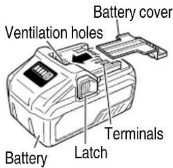
If an electrically conductive foreign object enters the terminals of the lithium ion battery, a short-circuit may occur resulting in the risk of fire. Please observe the following matters when storing the battery.
○ Do not place electrically conductive cuttings, nails, steel wire, copper wire or other wire in the storage case.
○ Either install the battery in the power tool or store by securely pressing into the battery cover until the ventilation holes are concealed to prevent short-circuits (See Fig. 4).
REGARDING LITHIUM-ION BATTERY TRANSPORTATION
When transporting a lithium-ion battery, please observe the following precautions.
WARNING
Notify the transporting company that a package contains a lithium-ion battery, inform the company of its power output and follow the instructions of the transportation company when arranging transport.
● Lithium-ion batteries that exceed a power output of 100 Wh are considered to be in the freight classification of Dangerous Goods and will require special application procedures.
- For transportation abroad, you must comply with international law and the rules and regulations of the destination country.
- If the BSL36B18 is installed in the power tool, the power output will exceed 100 Wh and the unit will be classified as Dangerous Goods for freight classification.
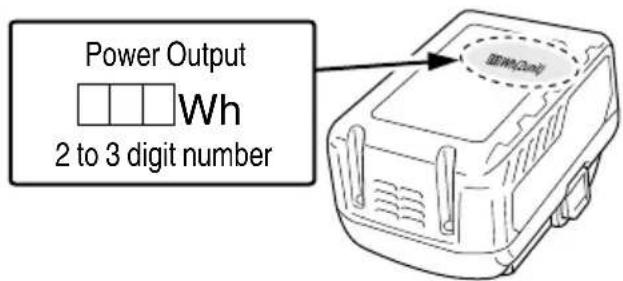
Fig. 1
USB DEVICE CONNECTION PRECAUTIONS
When an unexpected problem occurs, the data in a USB device connected to this product may be corrupted or lost. Always make sure to back up any data contained in USB device prior to use with this product. Please be aware that our company accepts absolutely no responsibility for any data stored in a USB device that is corrupted or lost, nor for any damage that may occur to a connected device.
SAVE THESE INSTRUCTIONS AND MAKE THEM AVAILABLE TO OTHER USERS AND OWNERS OF THIS TOOL!
The information contained in this Instruction Manual is designed to assist you in the safe operation and maintenance of the power tool. Some illustrations in this Instruction Manual may show details or attachments that differ from those on your own power tool.
NAME OF PARTS
- Cordless Slide Compound Miter Saw (C3607DRA)
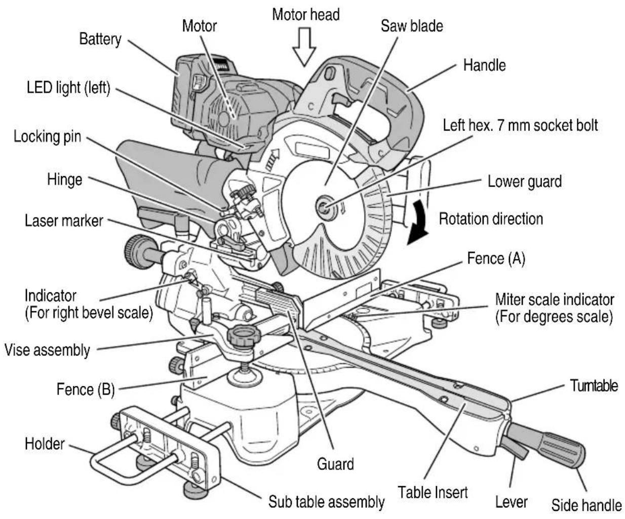
Fig. 2
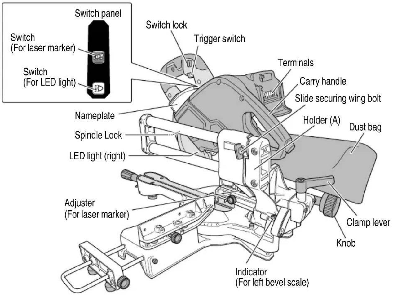
Fig. 3
-
Battery (optional accessories ... sold separately)
-
Battery Charger (optional accessories ... sold separately)
-
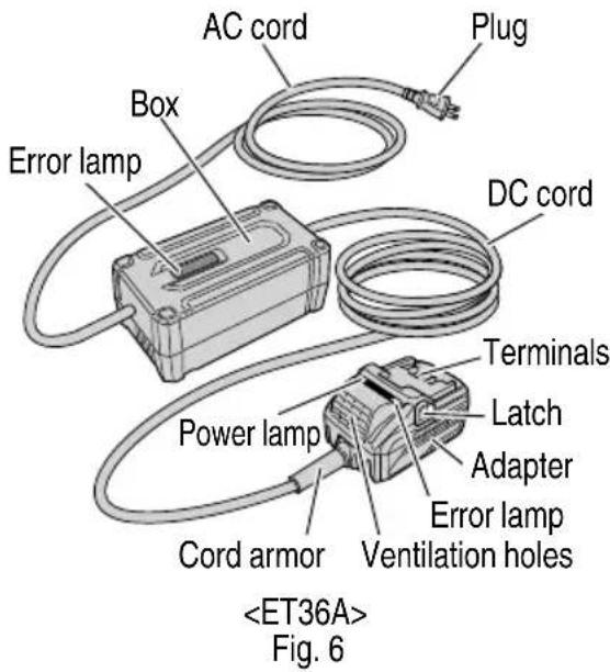
AC/DC Adapter (optional accessories ... sold separately)
SPECIFICATIONS
1. Cordless Slide Compound Miter Saw
| Item Model C3607DRA | |||||
| Motor DC brushless motor | |||||
| Laser Marker | Maximum output | Po<1 mW CLASS II Laser Product | |||
| Wave length | 400 - 700 nm | ||||
| Laser medium Laser Diode | |||||
| Applicable saw blade | Outside Dia. 7-1/4" (185 mm)Hole Dia. 5/8" (15.9 mm) | ||||
| No load speed | 4,000/min | ||||
| Max.sawing dimension | Head Turntable Max. sawing dimension | ||||
| Miter | 0 | 0 | (With aux. board)Max. HeightMax. Width(Without aux. board)Max. HeightMax. Width | 1" (25 mm)2-5/8" (67 mm)10-11/32" (263 mm)2-9/32" (58 mm)12-13/64" (310 mm) | |
| 0 | Left 45° or Right 45° | (With aux. board)Max. HeightMax. Width(Without aux. board)Max. HeightMax. Width | 3/4" (20 mm)2-5/8" (67 mm)7-7/32" (183 mm)2-9/32" (58 mm)8-37/64" (218 mm) | ||
| Bevel | Left 45° 0 | (With aux. board)Max. HeightMax. Width(Without aux. board)Max. HeightMax. Width | 1" (25 mm)1-25/32" (45 mm)10-11/32" (263 mm)1-17/32" (39 mm)12-13/64" (310 mm) | ||
| Right 45° 0 | (With aux. board)Max. HeightMax. Width(Without aux. board)Max. HeightMax. Width | 1" (25 mm)7/8" (22 mm)10-11/32" (263 mm)5/8" (16 mm)12-13/64" (310 mm) | |||
| Compound | Left 45° | Left 45° or Right 45° | (With aux. board)Max. HeightMax. Width(Without aux. board)Max. HeightMax. Width | 3/4" (20 mm)1-25/32" (45 mm)7-7/32" (183 mm)1-17/32" (39 mm)8-37/64" (218 mm) | |
| Right 45° | Right 45° | (With aux. board)Max. HeightMax. Width(Without aux. board)Max. HeightMax. Width | 3/4" (20 mm)7/8" (22 mm)7-7/32" (183 mm)5/8" (16 mm)8-37/64" (218 mm) | ||
| Left 31° | (With aux. board)Max. HeightMax. Width(Without aux. board)Max. HeightMax. Width | 3/4" (20 mm)7/8" (22 mm)8-25/32"(223 mm)5/8" (16 mm)10-5/32" (258 mm) | |||
| Miter sawing range Left 0° – 45° Right 0° – 57° | |||
| Bevel sawing range Left 0° – 45° Right 0° – 45° | |||
| Compound sawing range | Bevel (Left) 0° – 45° Miter (Left) 0° – 45°, (Right) 0° – 45° | ||
| Bevel (Right) 0° – 45° Miter (Right) 0° – 45°, (Left) 0° – 31° | |||
| Power supply | Type* | Li-ion battery Model BSL36B18AC/DC adapter Model ET36A (sold separately) | |
| Voltage 36V | |||
| Net weight 34.0 lbs. (15.4 kg) (BSL36B18 attached) | |||
* Existing batteries (BSL3660/3626/3620, BSL18xx and BSL14xx series, etc.) cannot be used with this tool.
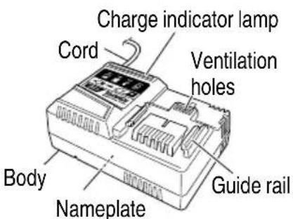
- Battery Charger
| Model UC18YSL3 | |
| Input power source Single phase: AC 120 V 60 Hz | |
| Charging time(At a temperature of 68°F (20°C)) | BSL36B18 : Approx. 52 min |
| Charging voltage DC 14.4 – 18 V | |
| Charging current DC 8.0 A | |
| Weight | 1.3 lbs. (0.6 kg) |
NOTE: The charging time may vary according to temperature and power source voltage.
- AC/DC Adapter
| Model | ET36A |
| Input power source Single phase: AC 120 V 60 Hz | |
| Output voltage | 36V |
| Operating temperature range | 14°F (-10°C) -104°F (40°C) |
| Weight | Adapter : 1.8 lbs. (0.8 kg)Box : 2.6 lbs. (1.2 kg) |
APPLICATIONS
Cutting various types of wood.
Pull out battery before carrying out any adjustment, servicing or maintenance.
When fi nished with a job, pull out the battery.
- Power source
Ensure that the power source to be utilized conforms to the power requirements specified on the product nameplate.
- Power switch
Ensure that the switch is in the OFF position. If the battery installed to power tool while the switch is in the ON position, the power tool will start operating immediately, which could cause a serious accident.
-
Remove all packing materials attached or connected to the tool before attempting to operate it.
-
Releasing the locking pin (Fig. 7)
When the power tool is prepared for shipping, its main parts are secured by a locking pin.
Move the handle slightly so that the locking pin can be disengaged.
During transport, lock the locking pin into the gear case.
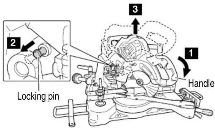
Fig. 7
- Installing the sub tables (Standard accessory) (Fig. 8)
The sub tables help keep longer workpieces stable and in place during the cutting operation.
(1) Loosen the 6 mm hex. socket bolts with 5 mm hex. bar wrench (standard accessory). Insert the holder into the base.
(2) Use a steel square for aligning the upper surface of the sub tables with the base surface.
Turn the set screws, and adjust the height of the sub tables.
(3) After adjustment, firmly tighten the 6 mm knob bolts and fasten the holder with the 6 mm hex. socket bolts. If the length of set screws is insufficient, spread a thin plate beneath.
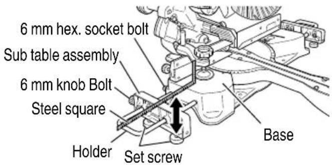
Fig. 8
CAUTION
When transporting or carrying the tool, do not grasp the sub tables or holders.
There is the danger of the sub tables or holders slipping out of the base. Grasp the carry handle instead of the sub tables or holders.
- Installing the side handle (Fig. 2)
Install the side handle that came enclosed with this unit.
-
Attach the dust bag to the main unit (Fig. 3)
-
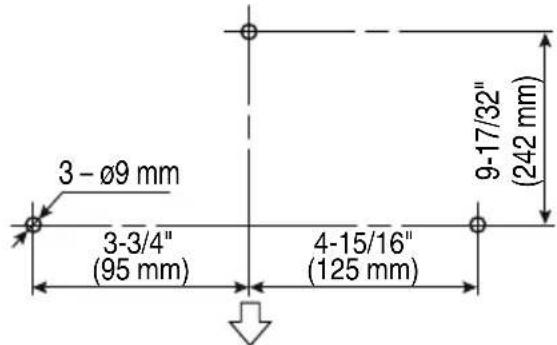
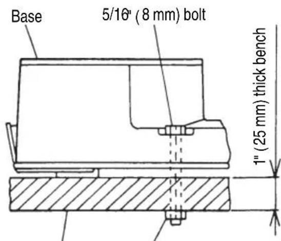
Installation (Fig. 9, 10)
Side of the side handle
Work bench
5/16" (8 mm) nut
Fig. 9
Ensure that the machine is always fixed to bench.
Attach the power tool to a level, horizontal work bench.
Select 8 mm diameter bolts suitable in length for the thickness of the work bench.
Bolt length should be at least 40 mm plus the thickness of the work bench.
For example, use 8 mm × 65 mm bolts for a 25 mm thick work bench.
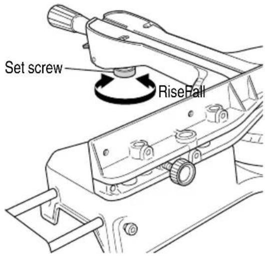
Fig. 10
Turn the setscrew left or right to adjust the setscrew for light contact with the floor.
REMOVAL AND INSTRUCTION METHOD OF BATTERY OR AC/DC ADAPTER
○ How to install the battery or AC/DC adapter.
Align the battery or AC/DC adapter with the groove in tool handle and slip it into place.
Always insert it all the way until it locks in place with a little click, If not, it may accidentally fall out of the tool, causing injury to you or someone around you (Fig. 11).
○ How to remove the battery or AC/DC adapter.
Withdraw battery or AC/DC adapter from the tool handle while pressing the latch (2 pcs) of the battery or AC/DC adapter (Fig. 11).
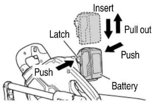
Fig. 11
CHARGING METHOD
NOTE
Before plugging into the receptacle, make sure the following points.
○ The power source voltage is stated on the nameplate.
○ The cord is not damaged.
WARNING
Do not charge at voltage higher than indicated on the nameplate.
If charged at voltage higher than indicated on the nameplate, the charger will burn out.
- Connect the charger's power cord to a receptacle. When the power cord is connected, the charge indicator lamp will blink in red. (At 1-second intervals)

WARNING
Do not use the electrical cord if damaged. Have it repaired immediately.
- Insert the battery to the battery charger.
Firmly Insert the battery into the battery charger as shown in Fig. 12.
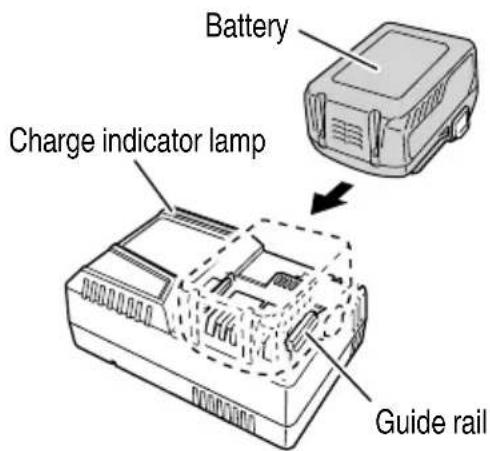
Fig. 12
- Charging
When inserting a battery in the charger, the charge indicator lamp will blink in blue.
When the battery becomes fully recharged, the charge indicator lamp will light up in green.(See Table 2)
(1) Charge indicator lamp indication
The indications of the charge indicator lamp will be as shown in Table 2, according to the condition of the battery charger or the battery.
Table 2
| Indications of the charge indicator lamp | ||||
| Charge indicator lamp (RED / BLUE / GREEN / PURPLE) | Before charging | Blinks (RED) | Lights for 0.5 seconds. Does not light for 0.5 seconds. (off for 0.5 seconds) | Plugged into power source |
| While charging | Blinks (BLUE) | Lights for 0.5 seconds. Does not light for 1 second. (off for 1 second) | Battery capacity at less than 50% | |
| Blinks (BLUE) | Lights for 1 second. Does not light for 0.5 seconds. (off for 0.5 seconds) | Battery capacity at less than 80% | ||
| Lights (BLUE) | Lights continuously | Battery capacity at more than 80% | ||
| Charging complete | Lights (GREEN) | Lights continuously(Continuous buzzer sound: about 6 seconds) | ||
| Overheat standby | Blinks (RED) | Lights for 0.3 seconds. Does not light for 0.3 seconds. (off for 0.3 seconds) | Battery overheated. Unable to charge. (Charging will commence when battery cools) | |
| Charging impossible | Flickers (PURPLE) | Lights for 0.1 seconds. Does not light for 0.1 seconds. (off for 0.1 seconds) (Intermittent buzzer sound: about 2 seconds) | Malfunction in the battery or the charger | |
(2) Regarding the temperature of the rechargeable battery.
The temperatures for rechargeable batteries are as shown in the Table 3, and batteries that have become hot should be cooled for a while before being recharged.
Table 3
| Rechargeable batteries | Temperatures at which the battery can be recharged |
| BSL36B18 | 32^ - 122^ (0^ - 50^) |
(3) Regarding recharging time (At 68°F (20°C))
Table 4 Charging time
| Battery\Charger | UC18YSL3 |
| BSL36B18 Approx. 52 min. | |
NOTE
The recharging time may vary according to the ambient temperature.
- Disconnect battery charger from the receptacle.

CAUTION
Do not pull the plug out of the receptacle by pulling on the cord.
Make sure to grasp the plug when removing from receptacle to avoid damaging cord.
- Remove the battery from the battery charger.
Supporting the battery charger with hand, pull out the battery from the battery charger.
NOTE
Be sure to pull out the battery from the battery charger after use, and then keep it.
| Regarding electric discharge in case of new batteries, etc. |
As the internal chemical substance of new batteries and batteries that have not been used for an extended period is not activated, the electric discharge might be low when using them the first and second time. This is a temporary phenomenon, and normal time required for recharging will be restored by recharging the batteries 2 – 3 times.
How to make the batteries perform longer
(1) Recharge the batteries before they become completely exhausted.
When you feel that the power of the tool becomes weaker, stop using the tool and recharge its battery. If you continue to use the tool and exhaust the electric current, the battery may be damaged and its life will become shorter.
(2) Avoid recharging at high temperatures.
A rechargeable battery will be hot immediately after use. If such a battery is recharged immediately after use, its internal chemical substance will deteriorate, and the battery life will be shortened. Leave the battery and recharge it after it has cooled for a while.
CAUTION
- When the battery charger has been continuously used, the battery charger will be heated, thus constituting the cause of the failures. Once the charging has been completed, give 15 rest until the next charging.
- If the battery is charged while it is heated because it has been left for a long time in a location subject to direct sunlight or because the battery has just been used, the charge indicator lamp of the charger lights for 0.3 seconds, does not light for 0.3 seconds (off for 0.3 seconds). In such a case, first let the battery cool, then start charging.
- When the charge indicator lamp flickers (at 0.2-second intervals), check for and take out any foreign objects in the charger's battery installation hole. If there are no foreign objects, it is probable that the battery or charger is malfunctioning. Take it to your authorized Service Center.
HOW TO RECHARGE USB DEVICE
WARNING
● Prior to use, check the connecting USB cable for any defect or damage.
Using a defective or damaged USB cable can cause smoke emission or ignition.
- When the product is not being used, cover the USB port with the rubber cover.
Buildup of dust etc. in the USB port can cause smoke emission or ignition.
NOTE
☐ The time required for charging will be longe a USB device and battery are being simultaneously charged.
- There may be an occasional pause during USB recharging.
When a USB device is not being charged, turn the USB power switch OFF and remove the USB device from the charger.
Failure to do so may not only reduce the battery life of a USB device, but may also result in unexpected accidents.
(1) Select a charging method
Depending on the charge method selected, either the battery is inserted into the charger or the power cord is plugged into an outlet.
○ Charging a USB device by battery (Fig. 13-a)
○ Charging a USB device from a electrical outlet (Fig. 13-b)
○ Charging a USB device and battery from a electrical outlet (Fig. 13-c)

a

natural_image
Simple line drawing of a device with a plug and cable, no text or symbols presentb
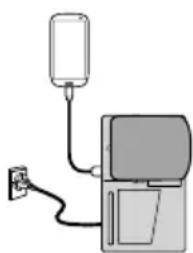
natural_image
Simple line drawing of a device with a bulb and power outlet (no text or symbols)C
Fig. 13
(2) Turn the USB power switch ON (Fig. 14)
When you turn the USB power switch ON, the USB power indicator lamp will light up.
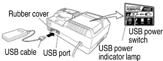
Fig. 14
(3) Connect the USB cable. (Fig. 14)
Pull back the rubber cover and firmly plug in a commercially available USB cable (appropriate to the device being charged) into the USB port.
When the power cord is not plugged into an outlet and the battery runs out of power, power output will stop and the USB power indicator lamp will shut off.
○ When the USB power indicator lamp goes out, change
the battery or plug the power cord into an electrical outlet.
(4) When charging is completed
☐ The USB power indicator lamp will not go out when a USB device has been completely charged.
To verify charge status, check the USB device.
○ Turn the USB power switch OFF and unplug the power cord from the electrical outlet. (Fig. 14)
○ Remove the battery from the charger and place the rubber cover over the USB port.
BEFORE USING
Power tool
WARNING
Check steps 1 through 6 before you have installed the power supply (battery) to the tool.
- Make sure the trigger switch is turned OFF.
WARNING
If the battery is inserted while the power switch is in the ON position, the power tool will start operating immediately, inviting serious accident.
- Check the saw blade for visible defects.
Confirm that the saw blade is free of cracks or other visible damage.
- Confirm that the saw blade is attached securely to the power tool.
Using the supplied 5 mm hex. bar wrench, tighten the left hex. 7 mm socket bolt on the saw blade spindle to secure the saw blade.
For details, see Fig. 51-a and Fig. 51-b in the section on "SAW BLADE MOUNTING AND DISMOUNTING".
- Check the lower guard for proper operation.
Lower guard is designed to protect the operator from coming into contact with the saw blade during operation of the tool.
Always check that the lower guard moves smoothly and covers the saw blade properly.
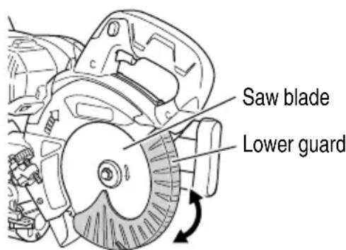
Fig. 15
WARNING
NEVER OPERATE THE POWER TOOL if the lower guard does not function smoothly.
- Confi rm the position of the spindle lock before using the tool.
After installing the saw blade, confirm that the spindle lock has been returned to the released position before using the power tool (see Fig. 3).
- Eye protection
Always wear eye protection with side shields that meets the requirements of ANSI Standard Z87.1. Ordinary eyeglasses do not provide adequate protection because they do not contain impact resistant safety glass.
WARNING
Operating the tool without wearing proper eye protection may result in serious injury.
AFTER INSTALLING THE POWER SUPPLY (BATTERY) TO THE TOOL, CHECK THE OPERATION OF THE TOOL AS FOLLOWS:
- Electric brake
This tool is equipped with an electric brake which will typically stop the blade within 5 seconds after the trigger switch is released.
Occasionally, there will be a delay in the brake engaging which will result in a longer blade stopping time. On rare occasions, the brake may not engage at all and the saw blade will coast to a stop.
If the brake fails to engage frequently, depress and release the trigger switch to turn the tool on and off 4 or 5 times. If the brake still does not engage, have the tool serviced at a metabo HPT authorized service center.
Always confirm that the saw blade has completely stopped before raising it from the workpiece.
The brake is not a substitute for a properly functioning lower guard. Check the function of the lower guard before each use. Serious personal injury may occur if the lower guard does not move smoothly and cover the blade properly.
WARNING
Please be aware of the reaction of the Motor Head (Fig.2) when the brake is activated. Braking causes the Motor Head to jerk downward and the user should be prepared for this reaction, especially when the trigger switch is released before the blade is completely down. Failure to
be familiar with, and prepared for, the operational characteristics of the tool may cause serious injury.
- Trial Run
After confi rming that no one is standing behind, the power tool start and confi rm that no operating abnormalities exist before attempting a cutting operation.
- Inspect the rotating stability of the saw blade.
For precise cutting, rotate the saw blade and check for deflection to confirm that the blade is not noticeably unstable; otherwise vibrations might occur and cause an accident.
AC/DC adapter
- Check the work area to make sure that it is clear of debris and clutter.
- Pos
Clear the area of unnecessary personnel. Ensure that lighting and ventilation are adequate. - To prevent electric shock, connect to a power source equipped with a ground fault circuit breaker.
- Prior to use, make sure that the DC cord insulation is not torn or that the case is not cracked.
Do not use the product if there is a break in the DC cord, the insulation is torn, or the case is damaged.
- Before starting operation, make sure that the vicinity of the box's vent is free from any wood shavings or iron powder.
Also, do not use in locations where iron powder is abundant, or in areas where there is rain, snow or other water sources that could wet the product.
- Make sure there are no solid metal material or liquid in the adapter box. Failure to do so may result in damage.
- Be careful not to step on the box. Also, make sure the box is placed in a location where it won't be stepped on. Do not place in a location where the box could be immersed in water when it rains.
BEFORE CUTTING
- Cutting a groove on the table insert (Fig. 16)
A groove has to be cut in the table insert, before starting operation. Secure a piece of wood about 300 mm (12") wide to the turntable with the vise assembly, to prevent the breakage of the table insert.
After the switch has been turned on and the saw blade has reached its maximum speed, slowly lower the handle to cut the piece of wood, and then a groove on the table insert.
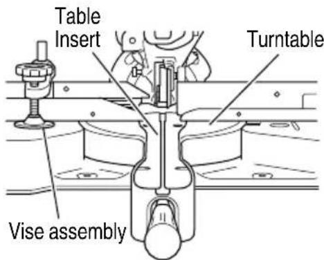
Fig. 16
CAUTION
Do not cut the groove too quickly; otherwise the guard might become damaged.
- Positioning the table insert
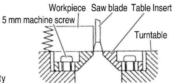
[Right angle cutting]
Fig. 17-a
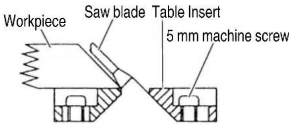
[Left bevel angle cutting]
Fig. 17-b
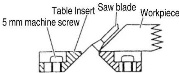
[Right bevel angle cutting]
Fig. 17-c
Table inserts are installed on the turntable. When shipping the tool from the factory, the table inserts are so fi xed that the saw blade does not contact them. The burr of the bottom surface of the workpiece is remarkably reduced, if the table insert is fi xed so that the gap between the side surface of the table insert and the saw blade will be minimum. Before using the tool, eliminate this gap in accordance with the following procedure.
(1) Right angle cutting
Loosen the four 5 mm pan head screws securing the cutting edge plate and with the gap between the left and right cutting edge plates widened, temporarily tighten all the 5 mm pan head screws. Then fi x a workpiece (about 200 mm wide) with the vise assembly and cut it off. Align the cutting face with the edge of the cutting edge plate, and tighten all the 5 mm pan head screws.
(2) Left and right bevel angle cutting
Adjust the table insert in the manner shown in Fig. 17-b and Fig. 17-c following the same procedure for right angle cutting.
CAUTION
After adjusting the table insert for right angle cutting, the table insert will be cut to some extent if it is used for bevel angle cutting.
When bevel cutting operation is required, adjust the table insert for bevel angle cutting.
- Checking the saw blade lower limit position
Check that the saw blade can be lowered 10 mm to 11 mm below the table insert.
When you replace a saw blade with a new one, adjust the lower limit position so that the saw blade will not cut the turntable or complete cutting cannot be done.
To adjust the lower limit position of the saw blade, follow the procedure (1) indicated below. (Fig. 18)
Furthermore, when changing the position of a 8 mm depth adjustment bolt that serves as a lower limit position stopper of the saw blade.
(1) Turn the 8 mm depth adjustment bolt, change the height where the bolt head and the hinge contacts, and adjust the lower limit position of the saw blade.
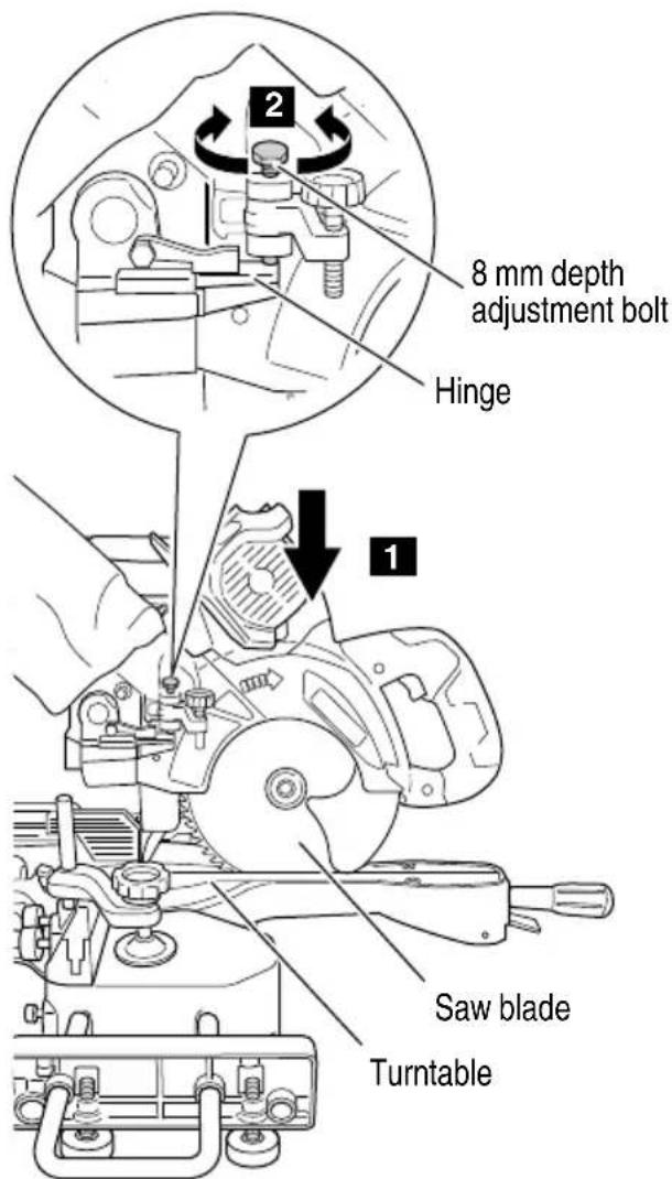
Fig. 18
NOTE
Confir rm that the saw blade is adjusted so that it w not cut into the turntable.
- Oblique angle
Before the power tool is shipped from the factory, it is adjusted for 0^ , right angle, left 45^ bevel cutting angle and right 45^ bevel cutting angle with the 8 mm set screw, 6 mm bolt (A) and 6 mm bolt (B).
When changing the adjustment, change the height of the 8 mm set screw, 6 mm bolt (A), or 6 mm bolt (B) by turning them.
When changing the bevel angle to the right 45^ , pull the set pin (A) on the direction shown in Fig. 19-b and incline the motor head to the right.
When adjusting the motor head to 0^ , always return the set pin (A) to its initial position as shown in Fig. 19-a.
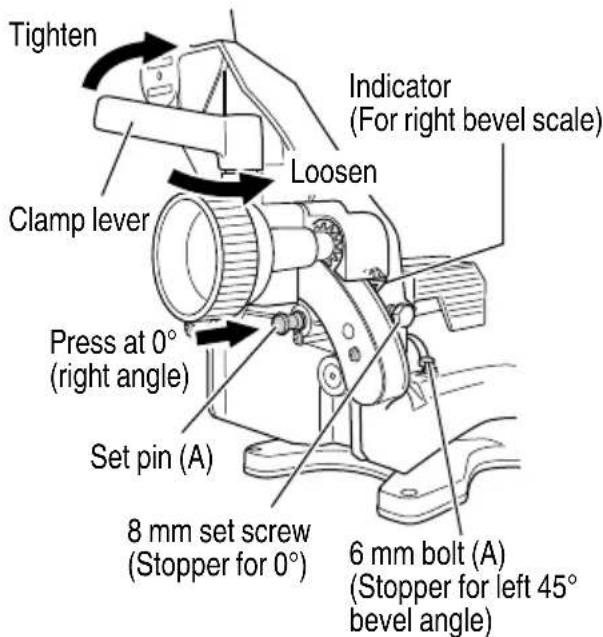
Fig. 19-a
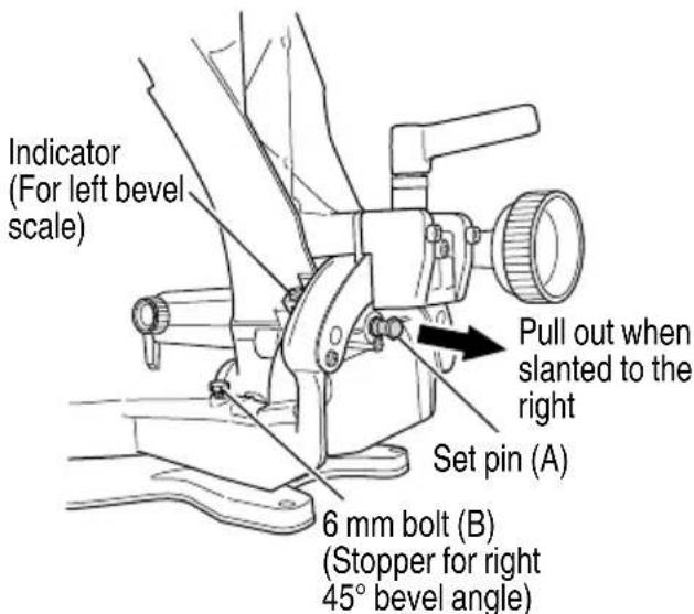
Fig. 19-b
5. Confirmation for use of sub fence (A) (Fig. 20-a)

WARNING
When right angle cutting, loosen the 6 mm knob bolt, then slide the sub fence (A) outward and remove it.
Failure to do so may result in the main body or saw blade coming into contact with the sub fence (A) and causing injury.
This power tool is equipped with a sub fence (A). In the case of direct angle cutting and left bevel angle cutting, use the sub fence (A). Then, you can realize stable cutting of the material with a wide back face.
When right angle cutting, loosen the 6 mm knob bolt, then remove sub fence (A). Failure to do so may result in the main body or saw blade coming into contact with the sub fence (A) and causing injury.
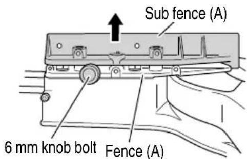
Fig. 20-a
NOTE
When transporting the saw, always secure the sub fence (A) in the collapsed position and lock it.
6. Confirmation for use of sub fence (B) (Fig. 20-b)

WARNING
When left angle cutting, loosen the 6 mm knob bolt, then slide the sub fence (B) outward. Failure to do so may result in the main body or saw blade coming into contact with the sub fence (B) and causing injury.
This power tool is equipped with a sub fence (B). In the case of direct angle cutting and right bevel angle cutting, use the sub fence (B). Then, you can realize stable cutting of the material with a wide back face. When left angle cutting, loosen the 6 mm knob bolt, then slide the sub fence (B) outward, as shown in Fig. 20-b.
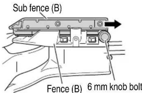
Fig. 20-b
NOTE
When transporting the saw, always secure the sub fence (B) in the collapsed position and lock it.
7. Adjusting the guard (Fig. 21)
(1) Right angle cutting
Loosen the 6 mm knob bolt and contact the tip of the guard with the workpiece.
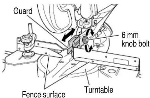
Fig. 21
CAUTION
In some arrangements when the turntable is rotated, the guard projects from the fence surface. Loosen the 6 mm knob bolt and push the guard to the retracted position. Never lift the lower guard while the saw blade is rotating. When cutting at an angle of 45^ to the right or more, please slide the guard to the rear. (Fig. 21)
The guard and sub-fence (A) and sub-fence (B) will not only make contact and adversely affect cutting accuracy, this could also result in damage to the guard.
8. Securing the workpiece
WARNING
Always clamp or vise to secure the workpiece to the fence; otherwise the workpiece might be thrust from the table and cause bodily harm.
9. Position adjustment of laser line
WARNING
Exercise utmost caution in handling a switch trigger for the position adjustment of the laser line, as the battery is installed during operation.
If the switch trigger is pulled inadvertently, the saw blade can rotate and result in unexpected accidents.
- Do not remove the laser marker to be used for other purposes.
CAUTION (Fig. 22)
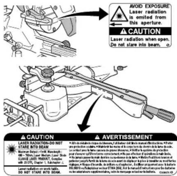
○ Laser radiation - Do not stare into beam.
○ Laser radiation on work table. Do not stare into beam. If your eye is exposed directly to the laser beam, it can be hurt.
○ Do not dismantle it.
Do not give strong impact to the laser marker (main body of tool); otherwise, the position of a laser line can go out of order, resulting in the damage of the laser marker as well as a shortened service life.
Keep the laser marker lit only during a cutting operation. Prolonged lighting of the laser marker can result in a shortened service life.
○ Use of controls or adjustments or performance of procedures other than those specified herein may result in hazardous radiation exposure.
NOTE
○ Perform cutting by overlapping the ink line with the laser line.
When the ink line and the laser line are overlapped, the strength and weakness of light will change, resulting in a stable cutting operation because you can easily discern the conformity of lines. This ensures the minimum cutting errors.
In outdoor or near-the-window operations, it may become difficult to observe the laser line due to the sunlight. Under such circumstances, move to a place that is not directly under the sunlight and engage in the operation.
Ink lining can be easily made on this tool to the laser marker. A switch lights up the laser marker (Fig. 2, 3).
Depending upon your cutting choice, the laser line can be aligned with the left side of the cutting width (saw blade) or the ink line on the right side.
The laser line is adjusted to the width of the saw blade at the time of factory shipment. Adjust the positions of the saw blade and the laser line taking the following steps to suit the use of your choice.
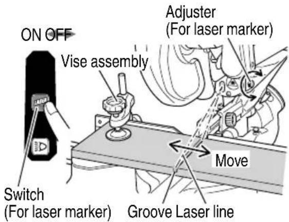
Fig. 23
(1) Light up the laser marker and make a groove of about 5 mm deep on the workpiece that is about 20 mm in height and 150 mm in width. Hold the grooved workpiece by vise as it is and do not move it. For grooving work, refer to "13. Groove cutting procedures" on page 35.
(2) Then, turn the adjuster and shift the laser line. (If you turn the adjuster clockwise, the laser line will shift to the right and if you turn it counterclockwise, the laser line will shift to the left.) When you work with the ink line aligned with the left side of the saw blade, align the laser line with the left end of the groove (Fig. 23). When you align it with the right side of the saw blade, align the laser line with the right side of the groove.
(3) After adjusting the position of the laser line, draw a right-angle ink line on the workpiece and align the ink line with the laser line. When aligning the ink line, slide the workpiece little by little and secure it by vise position where the laser line overlaps with the ink line. Work on the grooving again and check the position of the laser line. If you wish to change the laser line's position, make adjustments again following the steps from (1) to (3).
NOTE
Check and make sure on a periodic basis if the position of the laser line is in order. As regards the checking method, draw a right-angle ink line on the workpiece with the height of about 20 mm and the width of 150 mm, and check that the laser line is in line with the ink line [The deviation between the ink line and the laser line should be less than the ink line width (0.5 mm)]. (Fig. 24)
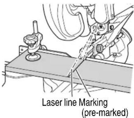
Fig. 24
PRACTICAL APPLICATIONS
WARNING
● To avoid personal injury, never remove or place a workpiece on the table while the tool is being operated.
● Never place your limbs inside of the line next to warning sign while the tool is being operated. This may cause hazardous conditions (see Fig. 25).
CAUTION
- It is dangerous to remove or install the while the saw blade is turning.
When sawing, clean off the shavings from the turntable.
○ If the shavings accumulate too much, the saw blade from the cutting material will be exposed. Never subject your hand or anything else to go exposed blade.
NOTE
at a Prior to operating the switch, make sure to check the stability of the tool by setting the angle and turn to conduct a trial cutting run without using a workpiece.
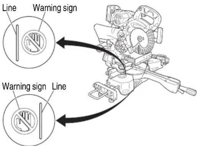
Fig. 25
1. Switch operation
(1) Turning the saw on (Fig. 26)
For safe operation of the machine, a "switch lock" is provided on the side of a handle.
If the "trigger switch" is pulled in a state where "switch lock" is pressed in the direction of the arrow mark, the main switch can be turned ON.
After the switch is on, the saw blade will continue to operate as long as you pull on the trigger switch, even if you release the switch lock.
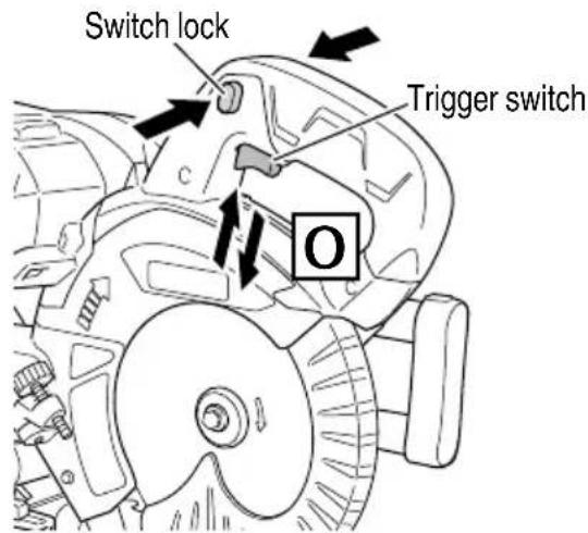
Fig. 26
(2) Turning the laser guide / LED light on (Fig. 27)
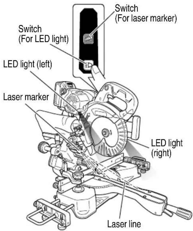
Fig. 27
The laser line will light when the laser marker switch is pressed on the switch panel. Press the switch once more to turn it off.
You can switch the lighting mode of the LED light by pressing the LED light switch. Turn the light off as much as possible to minimize battery consumption.
| Lighting Mode | Both Sides Lit Right Side Lit Left Side Lit OFF | |||
| LED Light (Right) | Light ON | Light ON | Light OFF | Light OFF |
| LED Light (Left) | Light ON | Light OFF | Light ON | Light OFF |
CAUTION
When the LED light has been lit or after immediately turning it off, the light lens becomes extremely hot and should never be touched.
NOTE
To minimize battery consumption when the LED lights and/or laser marker are left on, the unit will automatically switch them off if there is no operation for approximately one hour.
2. Using the Vise Assembly (Standard accessory)
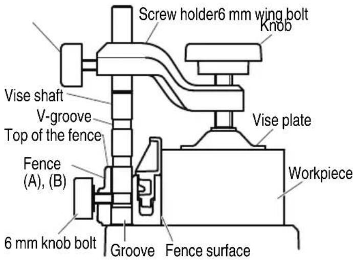
Fig. 28
The vice assembly can be attached on the right or left of the fence.
When attaching the vice assembly to the fence, matching the groove or the v-groove of the vice shaft to the upper surface of the fence will match the tip of the 6 mm knob bolt at the rear of the fence to the groove of the vice shaft.
This will allow 3 levels of height adjustment for the vice shaft.
(1) Adjust so that the tip of the 6 mm knob bolt matches the groove of the vice shaft, and tighten the 6 mm knob bolt to secure the vice shaft.
(2) Adjust the position of the screw holder, and tighten the 6 mm wing bolt on the rear of the screw holder to secure the screw holder.
(3) Make sure to press the material against the surface of the fence and secure the material by tightening the knob.
WARNING
Always fi rmly clamp or vise to secure the workpiece to the fence; otherwise the workpiece might be thrust from the table and cause bodily harm.
CAUTION
Always confirm that the motor head does not contact the vise assembly when it is lowered for cutting. If there is any danger that it may do so, move the vise assembly to a position where it will not contact the saw blade.
3. Cutting Operation
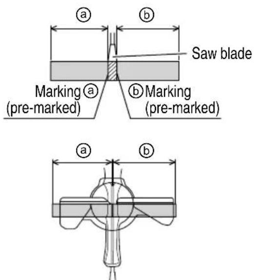
Fig. 29
(1) As shown in Fig. 29 the width of the saw blade is the width of the cut. Therefore, slide the workpiece to the right (viewed from the operator's position) when length ⓑ is desired, or to the left when length is desired.
If a laser marker is used, align the laser line with the left side of the saw blade, and then align the ink line with the laser line.
(2) Once the saw blade reaches maximum speed, push the handle down carefully until the saw blade approaches the workpiece.
(3) Once the saw blade contacts the workpiece, push the handle down gradually to cut into the workpiece.
(4) After cutting the workpiece to the desired depth, turn the power tool OFF and let the saw blade stop completely before raising the handle from the workpiece to return it to the full retract position.
CAUTION
- For maximum dimensions for cutting, refer to "SPECIFICATIONS" table on page 14.
- Increased pressure on the handle will not increase the cutting speed.
On the contrary, too much pressure may result in overload of the motor and/or decreased cutting efficiency.
WARNING
- Confi rm that the trigger switch is turned OFF and the battery has been removed whenever the tool is not in use.
● Always turn the power off and let the saw blade stop completely before raising the handle from the workpiece.
If the handle is raised while the saw blade is still rotating, the cut-off piece may become jammed against the saw blade causing fragments to scatter about dangerously.
● Every time one cutting or deep-cutting operation is finished, turn the trigger switch off, and check that the saw blade has stopped. Then raise the handle, and return it to the full retract position.
- Be absolutely sure to remove the (from the top of the turntable, and then proceed to the next step.
- Continued cutting operation can result in overload of the motor. Touch the motor and if it's hot, stop your cutting operation at once and rest for 10 minutes or so, and then restart your cutting operation.
- Cutting narrow workpieces (Press cutting) (Fig. 30)
Slide the hinge down to holder (A), then tighten the slide securing wing bolt (Fig. 3). Lower the handle to cut the workpiece. Using the power tool this way will permit cutting of workpieces of up to 58 mm height × 75 mm width.
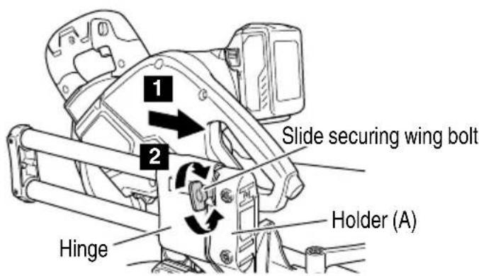
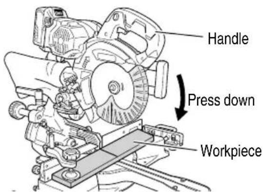
Fig. 30
- Cutting large workpieces (Fig. 31)
There may be case when a complete cutting cannot be done depending on the height of workpiece. In this case, mount an auxiliary board with the 6 mm fl at head screws and the 6 mm nuts using the 6.5 mm holes on the fence surface (two holes on each side). (Fig. 31)
Refer to page 14 "SPECIFICATIONS" for the thickness of the auxiliary board.
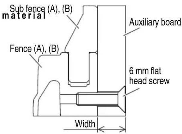
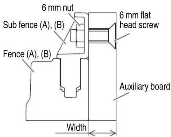
Fig. 31
NOTE
When cutting a workpiece exceeding 67 mm in height in right-angle cutting or 45 mm in left bevel angle cutting or 22 mm in right bevel angle cutting, adjust the lower limit position so that the base of the motor head will not come in contact with the workpiece.
To adjust the lower limit position of the saw blade, follow the procedure (1) and (2) shown in Fig. 32-a, b.
(1) Tilt the stopper (B) and turn the stopper holder on the side of the head towards the rear.
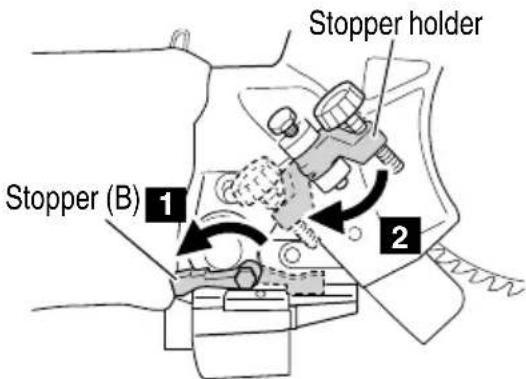
Fig. 32-a
(2) Lower the motor head, and turn the 8 mm depth adjustment bolt and make adjustments so that there can be a clearance of 2 mm to 3 mm between the lower limit position of the motor head and the top of the workpiece at the saw blade's lower limit position where the head of the 8 mm depth adjustment bolt contacts the hinge.
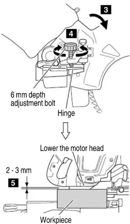
Fig. 32-b
- Cutting wide workpieces (Slide cutting)
(1) Workpieces up to 58 mm high and 310 mm wide: Loosen the slide securing wing bolt (Fig. 33), grip the handle and slide the saw blade forward. Then press down on the handle and slide the saw blade back to cut the workpiece. This facilitates cutting of workpieces of up to 58 mm in height 310 mm in width.
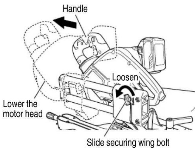
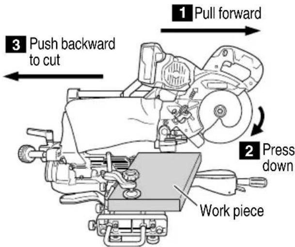
Fig. 33
(2) Workpieces up to 67 mm high and 263 mm wide: Workpieces of up to 67 mm in height 263 mm in width can be cut in the same manner as described in paragraph 4 above.
(3) Spacers (D) can be used to minimize burrs on the surface of materials when making slide cuts.
(a) Move the spacer (D) forward and place the stopper holder to the rear. (Fig. 34-a)
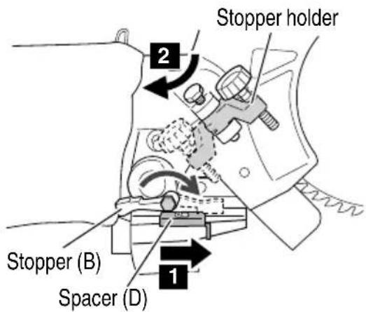
Fig. 34-a
(b) Lower the head and with the cutting edge of the sawblade in a position that lightly comes into contact with the workpiece, turn the 6 mm depth adjustment bolt so that the tip of the 6 mm bolt bumps against the spacer (D). (Fig. 34-b)
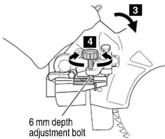
Fig. 34-b
(c) When you slide cut after returning spacer (D) to the rear, there will be a groove of about 2 mm. This will reduce scuffi ng of the workpiece's upper surface. (Fig. 34-c)
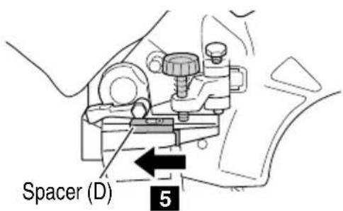
Fig. 34-c
(d) By moving the stopper holder forward and slide cutting once again, you can cut the workpiece.
CAUTION
- When cutting a workpiece of 67 mm height, adjust the lower limit position of the motor head so that the gap between the lower edge of the motor head and the workpiece will be 2 to 3 mm at the lower limit position. Refer to "5. Cutting large workpieces" on page 28.
- If the handle is pressed down with excessive or lateral force, the saw blade may vibrate during the cutting operation and cause unwanted cutting marks on the workpiece, thus reducing the quality of the cut.
Accordingly, press the handle down gently and carefully.
- In slide cutting, gently push the half (rearwards) in a single, smooth operation.
Stopping the handle movement during the cut will cause unwanted cutting marks on the workpiece.
WARNING
● For slide cutting, follow the procedures.
Forward slide cutting (toward the operator) is very dangerous because the saw blade could kick upward from the workpiece. Therefore, always slide the handle away from the operator.
● Always return the carriage to the full rear position after each crosscut operation in order to reduce the risk of injury.
● Never put your hand on the side handle during the cutting operation because the saw blade comes close to the miter lock handle when the motor head is lowered.
7. Miter cutting procedures
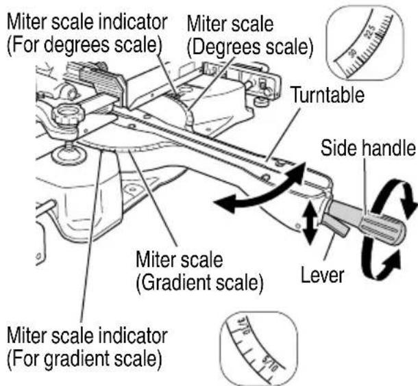
Fig. 35
(1) Loosen the side handle and pull up the lever for angle stoppers. Then, adjust the turntable until the indicator aligns with desired setting on the miter scale (Fig. 35).
(2) Re-tighten the side handle to secure the turntable in the desired position.
(3) The miter scale indicates both the cutting angle on the angle scale and the gradient on the grade scale.
(4) The gradient, which is the ratio of the height to the base of the triangular section to be removed, may be used for setting the miter scale instead of the cutting angle, if desired.
Therefore, to cut a workpiece at a grade of 2/10, set the indicator to position.
NOTE
Positive stops are provided at the right and left of the 0^ center setting, at 15^ , 22.5^ , 30^ and 45^ settings.
Check that the miter scale and the tip of the indicator are properly aligned.
Operation of the saw with the miter scale and indicator out of alignment, or with the side handle not properly tightened, will result in poor cutting precision.
- Bevel cutting procedures (Fig. 36)
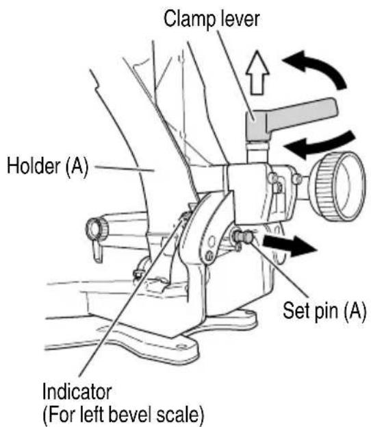
Fig. 36
(1) Loosen the clamp lever and bevel the saw blade to the left or to the right. When tilting the motor head to the right pull the set pin (A) towards the rear.
The clamp lever adopts a latchet system. When contacting the work bench and the main body, pull the clamp lever in the direction of the arrow mark as illustrated in Fig. 36, and change the direction of the clamp lever.
(2) Adjust the bevel angle to the desired setting while watching the bevel angle scale and indicator, then secure the clamp lever.
WARNING
When the workpiece is secured on the left or right side of the blade, the short cut-off portion will come to rest on the right or left side of saw blade. Always turn the power off and let the saw blade stop completely before raising the handle from the workpiece.
If the handle is raised while the saw blade is still rotating, the cut-off piece may become jammed against the saw blade causing fragments to scatter about dangerously.
When stopping the bevel cutting operation halfway, start cutting after pulling back the motor head to the initial position.
Starting from halfway, without pulling back, causes the lower guard to be caught in the cutting groove of the workpiece and to contact the saw blade.
CAUTION
When cutting a workpiece of 45 mm height in the left 45° bevel cutting position or a workpiece of 22 mm height in the right 45° bevel cutting position, adjust the lower limit position of the motor head so that the gap between the lower edge of the motor head and the workpiece will be 2 to 3 mm at the lower limit position (refer to "5. Cutting large workpieces" on page 28).
- Bevel angle fine adjustment
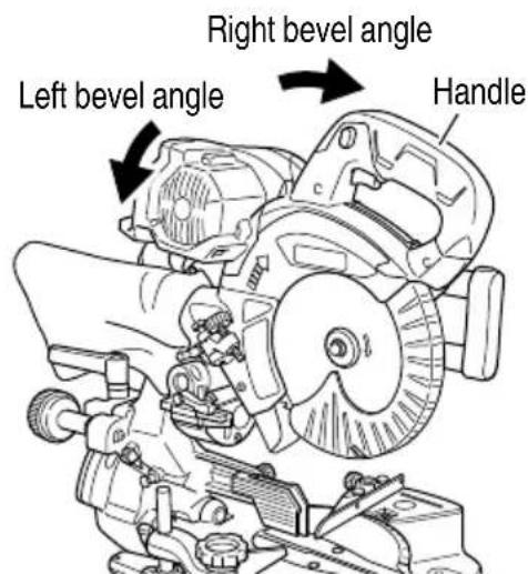
Fig. 37
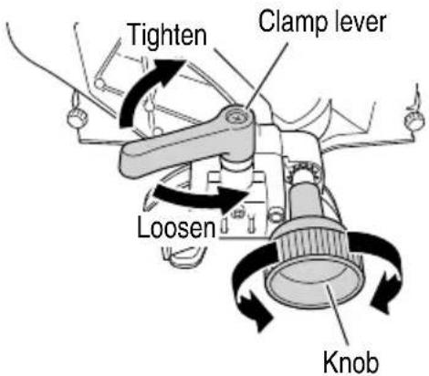
Fig. 38
(1) Grip the handle on the motor head and position it at the bevel angle you need. Temporarily tighten the clamp lever.
CAUTION
If not tightened firmly enough the motor head might suddenly move or slip, causing injuries. Be sure to tighten the motor head section enough so it will not move.
(2) Make fine adjustments to the bevel angle by gripping the handle and moving the knob.
NOTE
○ Turning knob clockwise, allows fine adjustment of the main unit to the left (as seen from front).
○ Turning knob counterclockwise, allows fine adjustment of the main unit to the right (as seen from front).
(3) After adjusting to the desired angle, tighten the clamp lever and clamp the motor head.
CAUTION
Always check that the clamp lever is secured and the motor head is clamped. If you attempt angle cutting without clamping the motor head, then the motor head might shift unexpectedly causing injuries.
- Compound cutting procedures
Compound cutting can be performed by following the instructions in 7 to 8 above. For maximum dimensions for compound cutting, refer to "SPECIFICATIONS" table on page 14.
CAUTION
Always secure the workpiece with the right or left hand and cut it by sliding the round portion of the saw backwards with the left hand.
It is very dangerous to rotate the turntable to the left during compound cutting because the saw blade may come into contact with the hand that is securing the workpiece.
In case of compound cutting (angle + bevel) by left bevel, slide the sub-fence (B) outward, and engage in the cutting operation.
In case of compound cutting (angle + bevel) by right bevel, remove the sub-fence (A), and engage in the cutting operation.
- Cutting long materials
When cutting long materials, use an auxiliary platform which is the same height as the holder and base of the special auxiliary equipment.
- Crown molding cutting procedures
Fig. 39 shows two common crown molding types having angles of (θ) 38° and 45°.
For the typical crown molding fittings, see Fig. 40.

Fig. 39
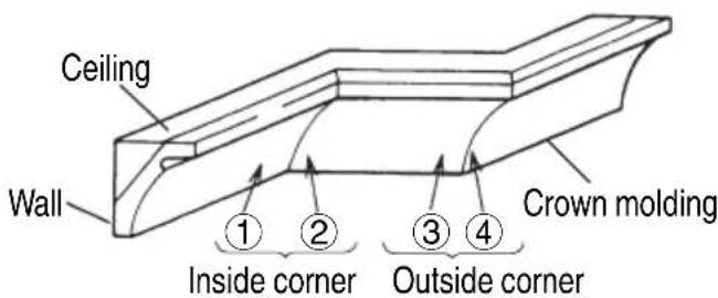
Fig. 40
The table below shows the miter angle and the bevel angle settings that are ideal for the two crown molding types.
NOTE
For convenience, positive stops are provided for the miter setting (left and right 31.6°) positions.
For miter cut setting
If the turntable has been set to either of the angles described, move the turntable adjusting side handle a little to the right and left to stabilize the position and to properly align the miter angle scale and the tip of the indicator before the operation starts.
For bevel cut setting
Turn the clamp lever on bevel section to the left and check that the position is stable and that the bevel angle scale and the tip of the indicator are properly aligned. Then tighten the clamp lever.
| Type of Crown Molding 45° Type 38° Type | ||
| To process crown molding at positions 1 and 4 in Fig. 40. | ||
| Miter Angle Setting | right35.3°(↓mark) | right31.6°(↓mark) |
| Bevel Angle Setting | left30°(↓mark) | left33.9°(↓mark) |
| To process crown molding at positions 2 and 3 in Fig. 40. | ||
| Miter Angle Setting | left35.3°(↓mark) | left31.6°(↓mark) |
| Bevel Angle Setting | left30°(↓mark) | left33.9°(↓mark) |
(1) Setting to cut crown moldings at positions ① and ④ in Fig. 40 (see Fig. 41; tilt the motor head to the left):
① Turn the turntable to the right and set the Miter Angle as follows:
○ For 45° type crown moldings: 35.3° ( mark)
○ For 38° type crown moldings: 31.6° ( mark)
② Tilt the motor head to the left and set the Bevel Angle as follows:
○ For 45° type crown moldings: 30° ( mark)
O For 38° type crown moldings: 33.9° ( mark)
③ Position the crown molding so that the upper surface (Ⓐ in Fig. 39) contacts the fence as indicated in Fig. 43.
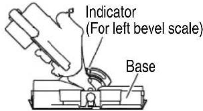
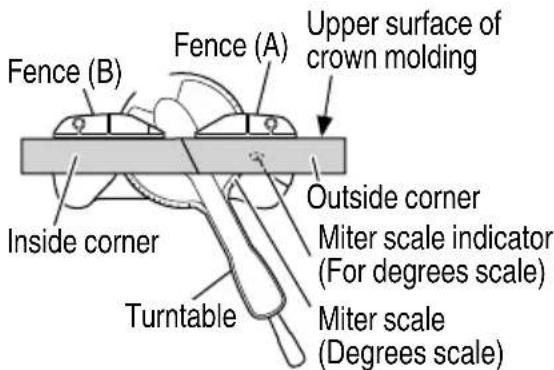
Fig. 41
(2) Setting to cut crown moldings at positions ② and ③ in Fig. 40 (see Fig. 42; tilt the head to the left):
① Turn the turntable to the left and set the Miter Angle as follows:
○ For 45° type crown moldings: 35.3°
○ For 38° type crown moldings: 31.6°
② Tilt the head to the left and set the Bevel Angle as follows:
○ For 45° type crown moldings: 30°
O For 38° type crown moldings: 33.9°
③ Position the crown molding so that the lower surface (⑧ in Fig. 39) contacts the fence as in Fig. 44.
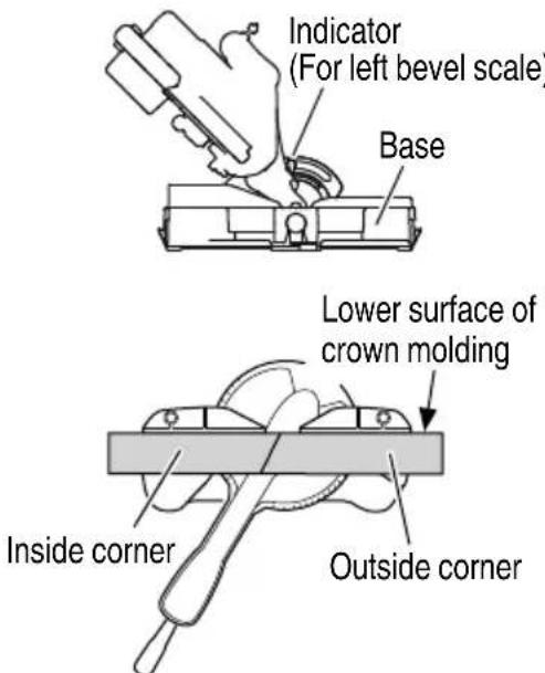
Fig. 42
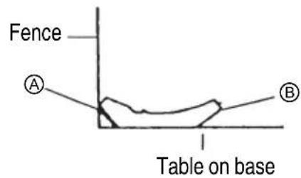
Fig. 43
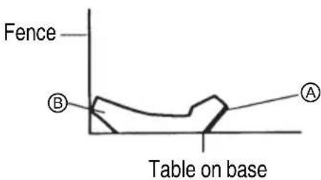
Fig. 44
(3) Setting to cut crown moldings at positions ① and ④ in Fig. 40 (see Fig. 45; tilt the head to the right):
① Turn the turntable to the right and set the Miter Angle as follows:
○ For 45° type crown moldings: 35.3°
○ For 38° type crown moldings: 31.6°
② Tilt the head to the right and set the Bevel Angle as follows:
○ For 45° type crown moldings: 30°
○ For 38° type crown moldings: 33.9°
③ Position the crown molding so that the upper surface (⑧ in Fig. 39) contacts the fence as indicated Fig. 47.
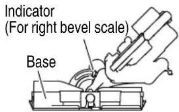
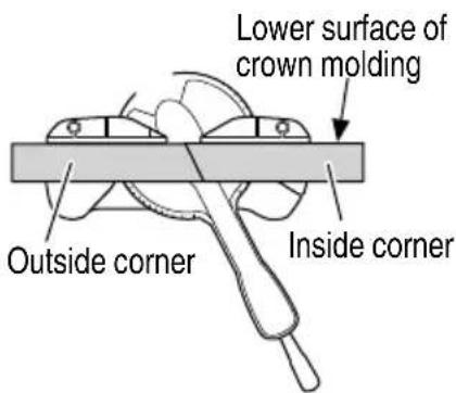
Fig. 45
(4) Setting to cut crown moldings at positions ② and ③ in Fig. 40 (see Fig. 46; tilt the head to the right):
① Turn the turntable to the left and set the Miter Angle as follows:
○ For 45° type crown moldings: 35.3°
○ For 38° type crown moldings: 31.6°
② Tilt the head to the right and set the Bevel Angle as follows:
○ For 45° type crown moldings: 30°
○ For 38° type crown moldings: 33.9°
③ Position the crown molding so that the lower surface (A in Fig. 39) contacts the fence as in Fig. 48.
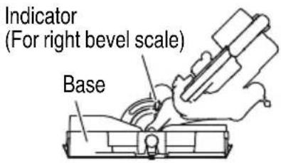
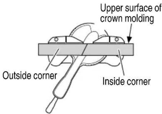
Fig. 46
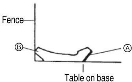
Fig. 47
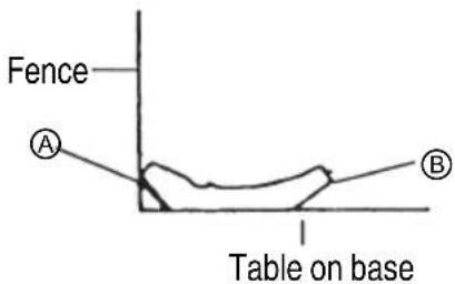
Fig. 48

WARNING
Always firmly clamp or vise to secure the crown molding to the fence; otherwise the crown molding might be thrust from the table and cause bodily harm.
- Groove cutting procedures
Cut grooves with saw blade
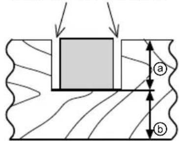
Fig. 49
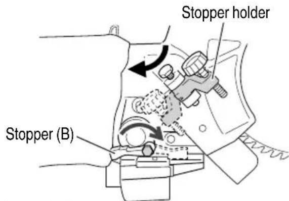
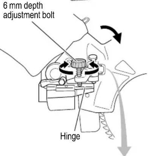
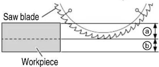
Fig. 50
Grooves in the workpiece can be cut by adjusting the 6 mm depth adjustment bolt (Fig. 50).
(1) Turn the stopper holder on the direction shown in Fig. 50.
Lower the motor head, and turn the 6 mm depth adjustment bolt by hand. (Where the head of the 6 mm depth adjustment bolt contacts the hinge.)
(2) Adjust to the desired cutting depth by setting the distance between the saw blade and the surface of the base (Fig. 50).
NOTE
When cutting a single groove at either end of the workpiece, remove the unneeded portion with a chisel.
(3) If the height of Ⓑ exceeds 20 mm, tip stopper (B) forward and press the tip of the 6 mm depth adjustment bolt against stopper (B).
NOTE
When using stopper (B), make sure to tip stopper (B) forward before placing the stopper holder to the rear.
- Using the dust bag (Standard accessory) (Fig. 51)
(1) Connect the dust bag with the duct of power tool.
(2) When the dust bag has become full of sawdust, dust will be blown out of the dust bag when the saw blade rotates.
Check the dust bag periodically and empty it before it becomes full.
(3) During bevel and compound cutting, attach the dust bag at the right angle to the base surface.
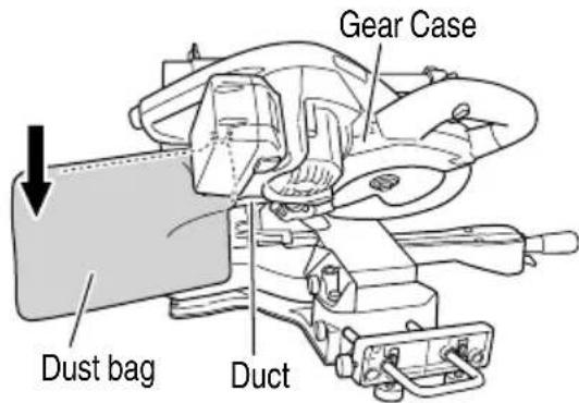
Fig. 51
- Connecting the dust extractor (Sold separately) (Fig. 52)
Do not inhale the harmful dusts generated in cutting operation.
The dust can endanger the health of yourself and bystanders.
Use of dust extractor can reduce dust related hazards.
By connecting with dust extractor through adapter, joint and dust collection adapter, most of dust can be collected.
Connect the dust extractor with adapter.
(1) Connect in order of hose (id 38 mm × 3 m long) and adapter (Dust extractor's Standard accessory) joint (Optional accessory) and dust collection adapter (Optional accessory) with the duct of power tool.
Connection is done by pressing in the direction of the arrow. (Fig. 52)
The dust collection adapter (Optional accessory) is fixed to the duct by a hose band. (Optional accessory)
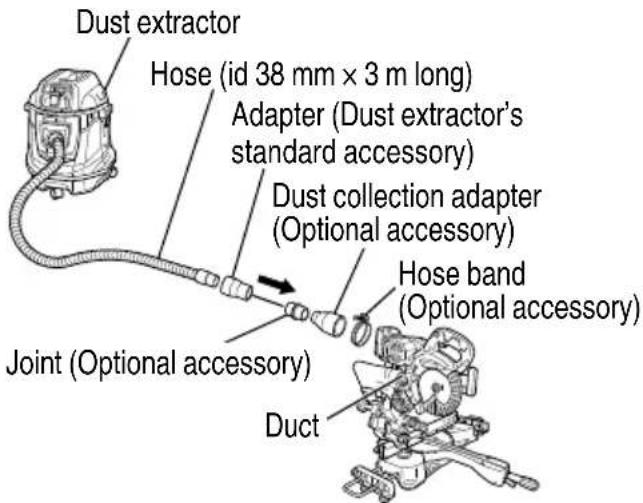
Fig. 52
- Using the AC/DC adapter ET36A (sold separately)
WARNING
Using the tool without securing the power cord could result in contact between the saw blade and cord that could result in electric shock.
(1) Attaching the hook assembly (Fig. 53) Using a Phillips screwdriver, firmly fasten the hook to the stopper holder with the screw.
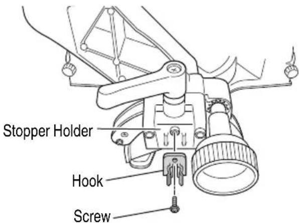
Fig. 53
(2) Securing the cord (Fig. 54, 55)
① Press down the saw head and secure in place with lock pin.
② Slide the saw head until it comes into contact with the front and secure the head with the slide securing wing bolt.
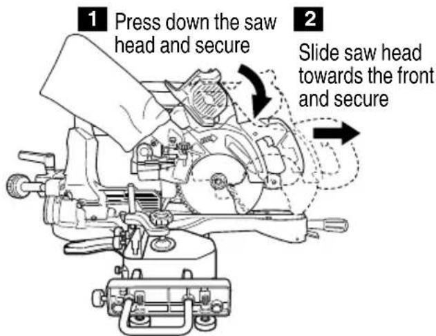
Fig. 54
③ Attach ET36A to the tool and secure the cord with the hook so that the cord is taut.
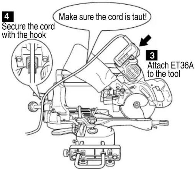
Fig. 55
SAW BLADE MOUNTING AND DISMOUNTING

WARNING
To prevent an accident or personal injury, always turn off the trigger switch and disconnect the battery from the power tool before removing or installing a saw blade.
- Mounting the saw blade (Fig. 56-a, 56-b)
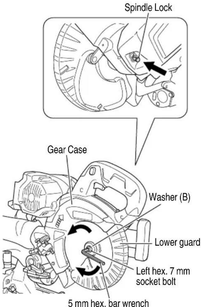
Fig. 56-a
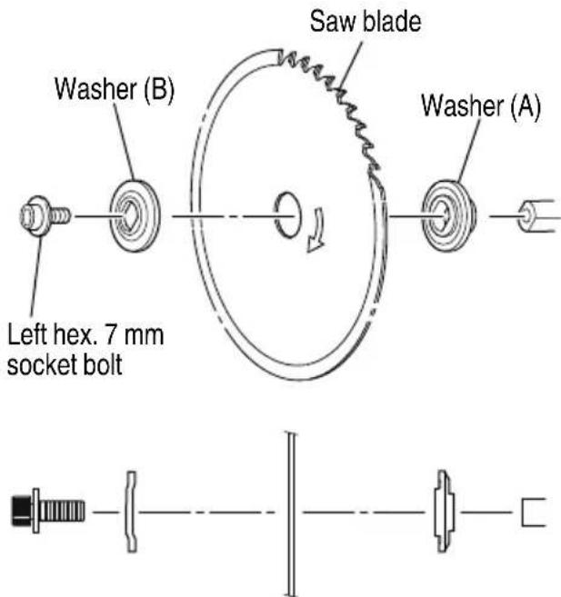
Fig. 56-b
(1) Press in spindle lock and loosen left hex. 7 mm socket bolt with 5 mm hex. bar wrench (standard accessory). Since the left hex. 7 mm socket bolt is left-hand threaded, loosen by turning it to the right.
NOTE
If the spindle lock cannot be easily pressed in to lock the spindle, turn the left hex. 7 mm socket bolt with 5 mm hex. bar wrench (standard accessory) while applying pressure on the spindle lock.
The saw blade spindle is locked when the spindle lock is pressed inward.
(2) Remove the bolt and washer (B)
(3) Lift the lower guard and mount the saw blade.
WARNING
When mounting the saw blade, confi rm that the rotation indicator mark on the saw blade and the rotation direction of the gear case are properly matched.
(4) Thoroughly clean washer (A) and the left hex. 7 mm socket bolt, and install them onto the saw blade spindle.
(5) Press in the spindle lock and tighten the left hex. 7 mm socket bolt by turning it to the left by standard accessories (5 mm hex. bar wrench).
CAUTION
○ A dust guide is installed inside behind the hinge. When removing or installing the saw blade, do not make contact with the dust guide. Contact may break or chip saw blade tips.
○ Tighten the left hex. 7 mm socket bolt so it does not come loose during operation.
○ Confi rm the left hex. 7 mm socket bolt has been properly tightened before the power tool is started.
○ Confi rm that the lower guard has closed position.
2. Dismounting the saw blade
Dismount the saw blade by reversing the mounting procedures described in paragraph 1 above.
The saw blade can easily be removed after lifting the lower guard.
CAUTION
Never attempt to install saw blades except 180 mm in diameter.
LED LIGHT WARNING SIGNALS
This product features functions that are designed to protect the tool itself as well as the battery. While the switch is pulled, if any of the safeguard functions are triggered during operation, the LED light will blink as described in Table 5. When any of the safeguard functions are triggered, immediately remove your finger from the switch and follow the instructions described under corrective action.
Table 5
ABOUT REMAINING BATTERY INDICATOR
You can check the battery's remaining capacity by pressing the remaining battery indicator switch to light the indicator lamp. (Fig. 57, Table 6)
The indicator will shut off approximately 3 seconds after the remaining battery indicator switch is pressed.
It is best to use the remaining battery indicator as a guide since there are slight differences such as ambient temperature and the condition of the battery.
Also, the remaining battery indicator may vary from those equipped to a tool or charger.
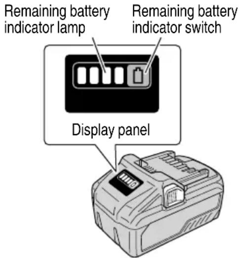
Fig. 57
Table 6
| State of lamp | Battery Remaining Power |
 | Lights;The battery remaining power is over 75%. |
 | Lights;The battery remaining power is 50% – 75%. |
 | Lights;The battery remaining power is 25% – 50%. |
 | Lights;The battery remaining power is less than 25%. |
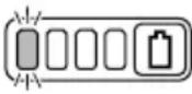 | Blinks;The battery remaining power is nearly empty. Recharge the battery soonest possible |
 | Blinks;Output suspended due to high temperature. Remove the battery from the tool and allow it to fully cool down. |
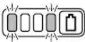 | Blinks;Output suspended due to failure or malfunction. The problem may be the battery so please contact your dealer. |
The Table 6 shows the state of remaining battery indicator lamp and the battery remaining power.
NOTE
Do not give a strong shock to the display panel or break it. It may lead to a trouble.
ABOUT ERROR LAMP OF AC/DC ADAPTER
Table 7
| Indications of the indicator lamp | |||||
| Status | Power Lamp (GREEN) | Error lamp (RED) | Indicates | ||
| Adapter | Before use | Blinks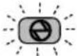 | Light off | Plugged into power source | |
| Power on | Lights | Light off | Tool can be used | ||
| Power suspended | Blinks Lights Lights | Blinks | Lights for 0.5 seconds. Does not light for 0.5 seconds. (off for 0.5 seconds) | Adapter cannot be used due to high temperature.(Can be used once the adapter is cooled) | |
| Lights for 0.1 seconds. Does not light for 0.1 seconds. (off for 0.1 seconds) | Overload | ||||
| Box | Power suspended | Blinks | Lights for 0.5 seconds. Does not light for 0.5 seconds. (off for 0.5 seconds) | Cannot be used because the temperature in the box is too high(Can be used once the box is cooled) | |
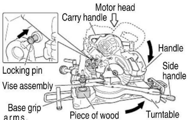
Fig. 58
TRANSPORTATION OF THE MAIN BODY
The vice assembly could be dropped during transportation. Either remove the assembly or slip a piece of wood between the vice to firmly secure it. (Fig. 58)
Drop the head and insert the locking pin (see page 16 "Releasing the locking pin").
Turn and loosen the side handle, turn the turntable as far right as it will go, and secure the turntable by turning the handle to the fixed position. This will make the main body even more compact.
When transporting the main body, carry it in your arms, holding the grip located on the base with both hands or carry handle.
MAINTENANCE AND INSPECTION
WARNING
To avoid an accident or personal injury, always confirm the trigger switch is turned OFF and that the battery or AC/DC adapter has been disconnected from the power tool before performing any maintenance or inspection of this tool. Report to qualified person as soon as possible, if you discover the fault of machine including guards or blade saw.
- Inspecting the saw blade
Always replace the saw blade immediately upon the first sign of deterioration or damage.
A damaged saw blade can cause personal injury and a worn saw blade can cause ineffective operation and possible overload to the motor.
CAUTION
Never use a dull saw blade. When a saw blade is dull, its resistance to the hand pressure applied by the tool handle tends to increase, making it unsafe to operate the power tool.
- About Handling the Motor (see Fig. 2)
Winding of the motor is said to be the heart of this tool. Exercise utmost caution not to damage the winding by exposing it to wash oil or water.
NOTE
Accumulation of dust and the like inside the motor can result in a malfunction.
After using the motor for 50 hours or so, carry out no-load running, and blow in the dry air from a wind hole at the motor's rear. Such action is effective to discharge dust and the like.
- Inspecting the screws
Regularly inspect each component of the power tool for looseness.
Re-tighten screws on any loose part.
WARNING
To prevent personal injury, never operate the power tool if any components are loose.
- Inspecting the lower guard for proper operation
Before each use of the tool, test the lower guard (see Fig. 15) to assure that it is in good condition and that it moves smoothly.
Never use the tool unless the lower guard operates properly and it is in good mechanical condition.
- Inspection of terminals (tool and battery or AC/DC adapter)
Check to make sure that swarf and dust have not collected on the terminals.
On occasion check prior, during and after operation.
CAUTION
Remove any swarf or dust which may have collected on the terminals.
Failure to do so may result in malfunction.
- Disposal of the exhausted battery
WARNING
Do not dispose of the exhausted battery. The battery must explode if it is incinerated. The product that you have purchased contains a rechargeable battery. The battery is recyclable. At the end of it's useful life, under various state and local laws, it may be illegal to dispose of this battery into the municipal waste stream. Check with your local solid waste offi cials for details in your area for recycling options or proper disposal.
7. Storage
After operation of the tool has been completed, check that the following has been performed:
(1) Trigger switch is in OFF position,
(2) Pull out the battery or AC/DC adapter from the tool.
When the tool is not in use, storing in a place below 104^ F ( 40^ C) and out of the reach of children.
NOTE
Storing lithium-ion batteries
Make sure the lithium-ion batteries have been fully charged before storing them.
Prolonged storage (3 months or more) of batteries with a low charge may result in performance deterioration, significantly reducing battery usage time or rendering the batteries incapable of holding a charge.
However, significantly reduced battery usage time may be recovered by repeatedly charging and using the batteries two to five times.
If the battery usage time is extremely short despite repeated charging and use, consider the batteries dead and purchase new batteries.
- Replacement of guard
After long-term use, the blade slot in the guard may widen and require replacement. If the blade slot should widen, replace the guard with a new one (Fig. 21). After replacing, make a groove on it.
9. Lubrication
Lubricate the following sliding surfaces once a month to keep the power tool in good operating condition for a long time (see Fig. 2 and Fig. 3). Use of machine oil is recommended.
Oil supply points:
○ Rotary portion of hinge
○ Rotary portion of vise assembly
○ Rotary portion of holder (A)
10. Cleaning
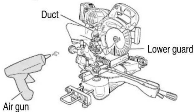
Fig. 59
Clean the machine, duct and lower guard by blowing with dry air from an air gun or other tool. (Fig. 59)
Periodically remove chips, dust and other waste material from the surface of the power tool, especially from the inside of the lower guard with a damp, soapy cloth. To avoid a malfunction of the motor, protect it from contact with oil or water.
If the laser line becomes invisible due to chips and the like adhered onto the window of the laser marker's light-emitting section, wipe and clean the window with a dry cloth or a soft cloth moistened with soapy water, etc.
Important notice on the batteries for the metabo HPT cordless power tools
Please always use one of our designated genuine batteries. We cannot guarantee the safety and performance of our cordless power tool when used with batteries other than these designated by us, or when the battery is disassembled and modified (such as disassembly and replacement of cells or other internal parts).
SERVICE AND REPAIRS
All quality power tools will eventually require servicing or replacement of parts because of wear from normal use. To assure that only authorized replacement parts will be used and that the double insulation system will be pr all service (other than routine maintenance) must be performed by an AUTHORIZED metabo HPT POWER TOOL REPAIR CENTER ONLY.
NOTE
Specifications are subject to change without any obligation on the part of metabo HPT.
TROUBLESHOOTING GUIDE
WARNING
● To avoid injury from an accidental start, turn the switch OFF and remove the plug from the power source or remove the battery or AC/DC adapter from the main body before making any adjustments.
● All electrical or mechanical repairs should be done only by qualified service technicians. Contact metabo HPT Authorized Service Center.
- Power tool
| Problem Possible | Cause Possible Solution | |
| Tool doesn't run No remaining battery power. Charge the battery. | ||
| The battery is not fully installed. Insert the battery into the tool until you hear a click. | ||
| Tool suddenly stopped Tool was overburdened. Get rid of the problem causing the overburden. | ||
| The battery is overheated. Let the battery cool down. | ||
| Cannot be tilted | The clamp lever has not been loosened. | Loosen the clamp lever and then tilt the tool.After adjusting the loosened component, make sure to tighten it once again. |
| Cannot be tilted to the right | Set pin (A) has not been pulled out. | Tilt to the right after pulling out set pin (A). |
| The clamp lever has not been loosened. | Loosen the clamp lever and then tilt. | |
| Sawblade is dull | The sawblade is worn down or missing teeth. | Exchange with a new product. |
| Bolt is loose. | Tighten the bolt. | |
| The sawblade has been installed in reverse. | Install the sawblade in the correct direction. | |
| Cannot cut with precision | The operation parts of the tool are not fully fixed. | Fully install the clamp lever and side handle. |
| Material cannot be fixed in the correct position. | Remove any foreign material from the fence or turntable. | |
| In some cases, proper position cannot be fixed due to a curve in the material.Try to fix a flat surface with the fence or turntable. | ||
| Switch cannot be pulled | Switch lock is not pressed in enough. | Press in the switch lock all the way until it strikes the back. |
| Battery cannot be installed | Attempting to install a battery other than that specified for the tool. | Please install a multi volt type battery. |
- Charger
| Symptom Possible | cause Remedy | |
| The charge indicator lamp is rapidly f l ickers purple, and battery charging doesn't begin. | The battery is not inserted all the way. | Insert the battery firmly. |
| There is foreign matter in the battery terminal or where the battery is attached. | Remove the foreign matter. | |
| The charge indicator lamp blinks red, and battery charging doesn't begin. | The battery is not inserted all the way. | Insert the battery firmly. |
| The battery is overheated. If left alone, the battery will automatically begin charging if its temperature decreases, but this may reduce battery life. It is recommended that the battery be cooled in a well-ventilated location away from direct sunlight before charging it. | ||
| Battery usage time is short even though the battery is fully charged. | The battery's life is depleted. Replace the battery with a new one. | |
| The battery takes a long time to charge. | The temperature of the battery, the charger, or the surrounding environment is extremely low. | Charge the battery indoors or in another warmer environment. |
| The charger's vents are blocked, causing its internal components to overheat. | Avoid blocking the vents. | |
| The cooling fan is not running. Contact a metabo HPT Authorized Service Center for repairs. | ||
| The USB power lamp has switched off and the USB device has stopped charging. | The battery's capacity has become low. Replace the battery with one that has capacity remaining. | |
| USB power lamp does not switch off even though the USB device has fi nished charging. | The USB power lamp lights up green to indicate that USB charging is possible. | This is not a malfunction. |
| It is unclear what the charging status of a USB device is, or whether its charging is complete. | The USB power lamp does not switch off even when charging is complete. | Examine the USB device that is charging to confi rm its charging status. |
| Charging of a USB device pauses midway. | The charger was plugged into an electrical socket while the USB device was being charged using the battery as the power source. | This is not a malfunction.The charger pauses USB charging for about 5 seconds when it is diff erentiating between power sources. |
| A battery was inserted into the charger while the USB device was being charged using a power socket as the power source. | ||
| Charging of the USB device pauses midway when the battery and the USB device are being charged at the same time. | The battery has become fully charged. This is not a malfunction.The charger pauses USB charging for about 5 seconds while it checks whether the battery has successfully completed charging. | |
| Charging of the USB device doesn’t start when the battery and the USB device are being charged at the same time. | The remaining battery capacity is extremely low. | This is not a malfunction.When the battery capacity reaches a certain level, USB charging automatically begins. |
- AC/DC adapter
| Problem Possible Cause Possible Solution | ||
| The adapter's error lamp is blinking red and the tool does not operate when switched on. | Output is suspended because the tool or the AC/DC adapter is overheated. | Allow the tool and AC/DC adapter to sufficiently cool down. |
| The adapter's error lamp rapidly blinks red and the motor does not operate when the tool is switched on. | Output is suspended because the tool is overloaded. | Remove the cause of the overload. |
| During protective operation, the LED will blink diff erently for AC/DC adapter use and battery use. | This is not a malfunction. | |
ACCESSORIES
WARNING
ALWAYS use Only authorized metabo HPT replacement parts and accessories. Never use replacement parts or accessories which are not intended for use with this tool. Contact metabo HPT if you are not sure whether it is safe to use a particular replacement part or accessory with your tool.
The use of any other attachment or accessory can be dangerous and could cause injury or mechanical damage.
NOTE
Accessories are subject to change without any obligation on the part of the metabo HPT.
STANDARD ACCESSORIES
| C3607DRA(NN) | 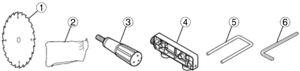 |
| 1 7-1/4" (185 mm) TCT saw blade (Code No. 374927M)....12 Dust bag (Code No. 322955M)....13 Side Handle (Code No. 322283)....14 Sub table assembly (Code No. 374638)....25 Holder (Code No. 998844)....26 5 mm hex. bar wrench (Code No. 944459)....1 |
OPTIONAL ACCESSORIES ... SOLD SEPARATELY
- Battery (BSL36B18)
- Battery charger (UC18YSL3)
- Battery cover (Code No. 329897)
- AC/DC adapter (ET36A)
- Vise Assembly (Code No. 374636)
- Hook (Code No. 374634)
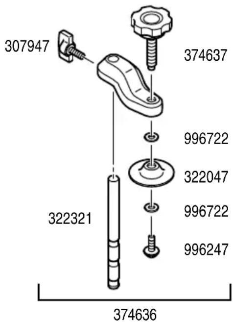
INFORMATIONS IMPORTANTES DE SÉCURITÉ
CHOSES A NE PAS FAIRE
POUR GARANTIR UNE UTILISATION EN TOUTE SÉCURITÉ, NE JAMAIS VIOLER LES CONSIGNES SUIVANTES:
natural_image
Simple line drawing of a device with a plug and cable, no text or symbols presenta
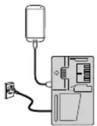
natural_image
Diagram of a device with a plug and cable, showing internal components without any text or symbolsb
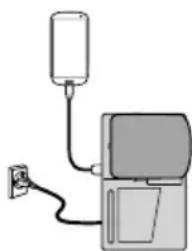
natural_image
Simple line drawing of a device with a bulb and power outlet (no text or symbols)C
Fig. 13
APPLICATIONS PRATIQUES

AVERTISSEMENT
TRANSPORT DU CORPS PRINCIPAL
natural_image
Simple line drawing of a device with a plug and cable, no text or symbols presenta
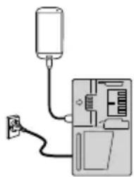
natural_image
Simple line drawing of a device with a plug and cable, no text or symbols presentb

natural_image
Simple line drawing of a device with a bulb and power outlet (no text or symbols)C
Fig. 13
Fig. 49

natural_image
Line drawing of a quill pen in an inkwell (no text or symbols)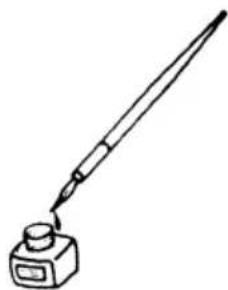
natural_image
Line drawing of a quill pen in an inkwell (no text or symbols)WARNING:
Some dust created by power sanding, sawing, grinding, drilling, and other construction activities contains chemicals known to the State of California to cause cancer, birth defects or other reproductive harm. Some examples of these chemicals are:
- Lead from lead-based paints,
- Crystalline silica from bricks and cement and other masonry products, and
- Arsenic and chromium from chemically-treated lumber.
Your risk from these exposures varies, depending on how often you do this type of work. To reduce your exposure to these chemicals: work in a well ventilated area, and work with approved safety equipment, such as those dust masks that are specially designed to filter out microscopic particles.
AVERTISSEMENT:
Please contact Koki Holdings America Ltd. at 1-800-59-TOOLS (toll free), or metabo HPT AUTHORIZED POWER TOOL SERVICE CENTER regarding COLLECTION.
Pour le RAMASSAGE, contacter Koki Holdings America Ltd. au 1-800-59-TOOLS (appel gratuit), ou UN SERVICE APRÈS-VENTE D'OUTILS ÉLECTRIQUE AGRÉÉ PAR metabo HPT.
Minato-ku, Tokyo 108-6020, Japan
Distributed by
Koki Holdings America Ltd.
1111 Broadway Ave,
Braselton, Georgia, 30517
Koki Holdings America Ltd. Canadian Branch
3405 American Drive, Units 9-10,
Mississauga, ON, L4V 1T6