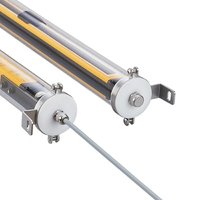
OY455S - Optoelectronic safety detector IFM - Free user manual and instructions
Find the device manual for free OY455S IFM in PDF.


User questions about OY455S IFM
0 question about this device. Answer the ones you know or ask your own.
Ask a new question about this device
Download the instructions for your Optoelectronic safety detector in PDF format for free! Find your manual OY455S - IFM and take your electronic device back in hand. On this page are published all the documents necessary for the use of your device. OY455S by IFM.
USER MANUAL OY455S IFM
CE
Original operating instructions
Photoelectric safety sensors
(safety light curtain)
with IP69K protective tube
for finger protection
(resolution / detection capacity 14 mm)
OY4xxS

Contents
1 Preliminary note....4
1.1 Symbols used ....4
1.2 Warning signs used ....4
2 Safety instructions ....5
2.1 Safety-related requirements regarding the application....6
3 Items supplied....7
4 Functions and features....7
5 Function....8
6 Installation....9
6.1 Installation instructions 9
6.2 Calculation of the minimum safety distance 11
6.3 Installation of the safety light curtains....12
6.3.1 Safety light curtains resolution 14 mm....12
6.4 Fixing and optical alignment 13
6.4.1 Optical alignment....13
6.5 Distance of reflective surfaces....14
6.6 Multiple systems....16
6.7 Use of corner mirrors....17
7 Electrical connection....18
7.1 Wiring diagram transmitter....18
7.2 Wiring diagram receiver....19
8 Operating modes 20
8.1 Automatic operation....21
8.2 Manual operation....21
8.3 Connection of external feedback contacts 22
8.4 Test function....22
8.4.1 Internal test function 22
9 Operating and display elements 23
9.1 LED indicators for optical alignment 23
9.1.1 Alignment in the automatic mode .....23
9.1.2 Alignment in the manual mode 24
9.2 LED states 25
10 Operation....26
10.1 Switching state of the outputs....26
10.1.1 The safe state....26
10.1.2 The switched state....26
10.1.3 Interface classification 26
10.2 Functional test of the safety light curtains 27
11 Scale drawing 28
12 Technical data....29
12.1 Heating 30
12.2 Safety light curtains: 14 mm resolution....30
13 Troubleshooting 30
13.1 Fault diagnosis transmitter .... 30
13.2 Fault diagnosis receiver....31
14 Maintenance, repair and disposal....32
15 Terms and abbreviations....33
16 Annex....34
16.1 Check list....34
1 Preliminary note
The instructions are part of the unit. They are intended for authorised persons according to the EMC and Low Voltage Directive and safety regulations. The instructions contain information about the correct handling of the product. Read the instructions before use to familiarise yourself with operating conditions, installation and operation. Adhere to the safety instructions.
1.1 Symbols used
▶ Instructions
▷ Reaction, result
→ Cross-reference
O LED off
LED on
LED flashes
Important note
Non-compliance can result in malfunction or interference.
Information
Supplementary note.

Access prevention finger protection
1.2 Warning signs used
WARNING
Warning of serious personal injury.
Death or serious irreversible injuries may result.
2 Safety instructions
- Follow the operating instructions.
- In case of non-observance of notes or standards, specially when tampering with and / or modifying the unit, any liability and warranty is excluded.
- The unit must be installed, connected and put into operation by a qualified electrician trained in safety technology.
- The applicable technical standards for the corresponding application must be complied with.
- For the installation the standards EN 60204, EN 999 and ISO 13855 have to be observed.
- In case of malfunction of the unit please contact the manufacturer. Tampering with the unit is not allowed.
- Disconnect the unit externally before handling it. Disconnect all relay load circuits that are supplied independently.
• After set-up the system has to be subjected to a complete function check. - Only use the unit under the specified operating conditions ( → 12 Technical data). In case of special operating conditions please contact the manufacturer.
- In case of any questions concerning safety - if required - contact the safety expert in charge of your country.

WARNING
In case of improper handling of the product, the safety and physical integrity of operators and machinery cannot be guaranteed.
Death or serious irreversible injuries may result.
▶ Observe all notes on installation and handling in these instructions.
▶ The photoelectric safety sensors must only be used under the specified operating conditions and in accordance with use as prescribed below.
2.1 Safety-related requirements regarding the application
It must be ensured that the safety requirements of the respective application correspond to the requirements stated in these instructions.
Observe the following requirements:
▶ Adhere to the specified operating conditions ( → 12 Technical data). Use of the photoelectric safety sensors in the vicinity of ionising radiation is not permitted. Furthermore, their use in the vicinity of chemically and biologically active media is to be checked, if necessary.
▶ Material resistance tests of the photoelectric safety sensors with a protective tube have been carried out for applications in the food industry. For the tested chemicals see the respective ECOLAB certificate or contact your ifm branch office.
▶ Adhere to the principle of normally closed operation for all external safety circuits connected to the system.
▶ If the photoelectric safety sensors go into the state defined as safe due to an internal fault, measures have to be taken to maintain the safe state when the installation resumes operation.
▶ Replace damaged units.
The protective function of the photoelectric safety sensors is only ensured with the following conditions:
- The machine control can be electrically controlled and the hazardous machine motion can be stopped immediately at any time of the operation cycle.
- There is no danger for machine operators due to ejection of materials or machine parts.
- The hazardous area is only accessible via the protected area.
3 Items supplied
- 2 photoelectric safety sensors (1 transmitter and 1 receiver) with IP69K protective tube
- 1 operating instructions photoelectric safety sensors with IP69K protective tube, reference number 704858
If one of the above-mentioned components is missing or damaged, please contact one of the ifm branch offices.
4 Functions and features

P = protected area; I = protected area width (range) H = protected area height
The OY4xxS safety light curtains are multi-beam optoelectronic protective devices to IEC 61496 and consist of one transmitter and one receiver.
5 Function
The protected area (P) is generated between the transmitter and the receiver and is defined by the protected area height (H) and the protected area width (range) (I).
The protected area height is the height protected by the safety light curtain. It depends on the design ( → 12 Technical data).
If the safety light curtains are installed horizontally, this value indicates the depth of the protected area.
The protected area width (range) is the maximum distance between transmitter and receiver ( → 12 Technical data).
If the protected are is clear, the two outputs (OSSDs) of the receiver are active.
If an object (O) with a diameter greater than or equal to the resolution (d) enters the protected area, the outputs are switched off.
The resolution (d) (detection capability) of the safety light curtain depends on the lens diameter (B) and the lens distance (C) and remains constant at all application conditions.

O = object
C = lens distance
B = lens diameter
d = resolution

To ensure that an object (O) is reliably detected in the protected area the dimensions of the object (O) must be at least as great as the resolution (d).
6 Installation
6.1 Installation instructions
The following conditions are to be ensured before installation of the photoelectric safety sensors:
- The degree of protection of the electro-sensitive equipment (ESPE) has to correspond with the risk assessment of the machine to be monitored.
- The safety system ensures a safety function and is not required for the operation of a machine.
- It must be possible to stop any hazardous motion of the machine immediately. In this respect the shutdown delay of the machine has to be determined.
- The object to be detected must be greater than or equal to the resolution of the photoelectric safety sensor.

▶ Install the photoelectric safety sensors so that the hazardous area can only be accessed via the protected area. Depending on the application other mechanical protective equipment may be necessary.
The operating conditions at the mounting location must not affect the functioning of the photoelectric safety sensors. Please note especially:
- The transmitter and the receiver must not be affected by intensive light sources (emitters, sunlight etc.).
- The ambient temperature must be within the range indicated ( → 12 Technical data).
- Fogging of the lenses due to considerable temperature fluctuations can affect the functioning of the photoelectric safety sensors. Take appropriate measures to prevent this.
- Certain operating conditions can affect the functioning of the photoelectric safety sensors. For mounting locations where fog, rain, smoke or dust may occur, it is recommended to take appropriate measures.
• The standards EN 999 and ISO 13855 must be adhered to.

Observe the following illustrations for correct installation of the photoelectric safety sensors.
Correct installation


Wrong installation


6.2 Calculation of the minimum safety distance
There must be a minimum safe distance between the photoelectric safety sensor and the point of danger. This distance must be ensured so that the point of danger cannot be accessed before the hazardous state of the machine has been stopped.

▶ Install the photoelectric safety sensor at a distance that is greater than or equal to the minimum safety distance (S) so that the hazardous area (A) can only be accessed after complete standstill of the hazardous machine motion.
According to the European Standard EN 999:2008 the following formula is to be used to calculate the minimum safety distance (S):
S = K (t 1 + t 2) + C
C = 8 (d - 1 4)
A = hazardous area
H = protected area height
S = minimum safety distance
C = additional distance
| S | Minimum safety distance | mm |
| K | Speed of approach of the object towards the hazardous area | mm/s |
| t1 | Total response time of the protective equipment, from release to switching off | s |
| t2 | Total response time of the machine, from the stop signal to switching off or to passing into the state defined as safe | s |
| C | Additional distance | mm |
| d | Resolution (detection capacity) | mm |

Non-compliance with the minimum safety distance may lead to restrictions to or loss of the safety function.
Application example:

A = hazardous area
S = min. safety distance
6.3 Installation of the safety light curtains
6.3.1 Safety light curtains resolution 14 mm

These designs are suitable for access prevention of fingers (finger protection).
The minimum safety distance (S) is determined using the following formula:
S = 2 0 0 0 (t _ 1 + t _ 2) + 8 (d - 1 4)
This formula applies to minimum safety distances (S) between 100 and 500 mm.
The min. safety distance (S) must be > 100 mm.

A = hazardous area
H = height
S = min. safety distance
G = reference level
If due to the special configuration of the machine it should be possible to reach the hazardous area from above, the highest light beam of the safety light curtain should be at a height (H) (measured from the reference level (G)) whose value is determined to the specifications in ISO 13855.
6.4 Fixing and optical alignment

Correct alignment of the transmitter and the receiver is decisive for the proper function of the photoelectric safety sensors.

▶ Install the transmitter and the receiver so that they are exactly opposite each other.
6.4.1 Optical alignment


T = transmitter; R = receiver
▶ Align the transmitter and the receiver so that they are in parallel at the same height and the cables face the same direction.
▶ Fix the transmitter and the receiver.
The indication LEDs of the receiver help to correctly align the photoelectric safety sensors. ( → 9.1 LED indicators for optical alignment)
6.5 Distance of reflective surfaces

Reflective surfaces close to photoelectric safety sensors can disable the safety function of the system.
The minimum distance (D) depends on the protected area width (I) taking into consideration the projection and receiving angles.

The minimum distance (D) between reflective surfaces and the protected area (P) must be observed. In case of non-compliance an object which has to be detected cannot be sensed. In case of improper handling of the product, the safety and physical integrity of operators and machinery cannot be guaranteed.

D = minimum distance; I = protected area width (range); P = protected area
▶ After installation test by intended interruption of the protected area (P) if reflective surfaces affect the function of the photoelectric safety sensors.
Minimum distance to reflective surfaces

D = minimum distance in [mm]; I = protected area width (range) [m]
6.6 Multiple systems

The use of several safety light curtains can lead to malfunction and disable the protective function.
The safety light curtains are to be installed so that the beam sent by the transmitter of a system can only be detected by the respective receiver.
The following important rules for installation are to be observed to avoid mutual interference of several systems:
Arrangement A

Possible arrangements:
A: Position of both transmitters next to each other
B: Position transmitter 1 and receiver 2 on top of each other
C: Combination in "L" shape
Arrangement C

Arrangement B


T = transmitter; R = receiver
6.7 Use of corner mirrors
To protect and monitor hazardous areas with access from several sides one or several corner mirrors can be used (available as accessory). By using mirrors the light beam emitted by the transmitter can be sent via several access sides.
▶ To obtain a reflection angle of 90° the mirrors are to be oriented in an angle of inclination of 45° .
The following image shows an application where U-shaped access protection is implemented using two mirrors.

A = hazardous area
M = corner mirror
S = minimum safety distance
Dx = side length
▶ Install the corner mirrors so that the minimum safety distance (S) is adhered to at each side of the hazardous area.
▶ During installation make sure that the reflecting area is plane and that no vibrations affect the safety device.
- The range is the sum of the length of all sides (D1 + D2 + D3) of the access to the protected area. The maximum range of the photoelectric safety sensors is reduced by 15% for each mirror.
- Do not use more than three mirrors.
7 Electrical connection
▶ Disconnect power. Also disconnect any independently supplied relay load circuits.

The nominal voltage is 24 V DC. This voltage may vary between 19.2 V and 28.8 V.

In case of a single fault the operating voltage must not exceed a maximum of 28.8 V DC. Therefore a safe separation between current supply and transformer is necessary.

To guarantee functional reliability an output capacity of min. 2000 µ F / A has to be ensured if a power supply with diode bridge is used.
▶ Connect the units as indicated in the following tables:
7.1 Wiring diagram transmitter
| Core colours | Name | Type | Description |
| brown | L+ (24 V DC) | Input | Operating voltage |
| white | Range 0 | Configuration protected area width | |
| blue | L- (0 V DC) | Operating voltage | |
| green | Range 1 | Configuration protected area width | |
| grey | FE | Functional earth | |
| red | 24 V AC / DC | Heating 24 V AC / DC | |
| yellow | 0 V DC | Heating 0 V DC | |
| pink | n.c. | not connected |
The protected area width (range) to be used is configured via range 0 and range 1.
Configuration protected area width (range)
| Range 0 | Range 1 | Description |
| 24 V | 0 V | Selection range low (0...2 m) |
| 0 V | 24 V | Selection range high (1...5 m) |
| 0 V | 0 V | Transmitter in test function (→ 8.4 Test function) |
| 24 V | 24 V | No function, configuration error |

For proper function of the safety light curtains the white and green cores of the transmitter have to be connected according to the indications in the above table.
7.2 Wiring diagram receiver
| Core colours | Name | Type | Description |
| white | OSSD1 | Output | Static safety-related output 1 |
| brown | 24 V DC | - | Operating voltage 24 V DC |
| green | OSSD2 | Output | Static safety-related output 2 |
| yellow | K1_K2/Restart | Input | External feedback contacts |
| grey | SEL_A | Input | Safety light curtains operating mode |
| pink | SEL_B | Input | |
| blue | 0 V DC | - | Operating voltage 0 V DC |
| red | FE | - | Functional earth |
| violet | 24 V AC / DC | - | Heating 24 V AC / DC |
| black | 0 V DC | - | Heating 0 V DC |

Note: Lay the cables of the photoelectric safety sensors separately from sources of interference such as power lines.
▶ Connect the transmitter and the receiver to the functional earth.
8 Operating modes
The different operating modes of the safety light curtains of the OY4xxS series can be set via the respective connections to the receiver.
| Operating modes | Connections | ||
| yellow | grey | pink | |
A Automatic | K1_K2 Connection to:L+ (24 V DC) | SEL_AConnection to:L+ (24 V DC) | SEL_BConnection to:L- (0 V DC) |
B Automatic with monitoring of the feedback contacts | K1_K2 Connection to:L+ (24 V DC)(via NC of the feedback contacts) | SEL_AConnection to:L+ (24 V DC) | SEL_BConnection to:L- (0 V DC) |
C Manual | K1_K2 /restart Connection to:L+ (24 V DC)(via start button) | SEL_AConnection to:L- (0 V DC) | SEL_BConnection to:L+ (24 V DC) |
D Manually with monitoring of the feedback contacts | K1_K2 /restart Connection to:L+ (24 V DC)(via start button and NC of the feedback contacts) | SEL_AConnection to:L- (0 V DC) | SEL_BConnection to:L+ (24 V DC) |
| 1: Feedback contact 1 Core colours:2: Feedback contact 2YE (yellow), GY (grey), PK (pink), RD (red)3: Restart | |||
8.1 Automatic operation
If the safety light curtains are used in the automatic mode, monitored start is not possible.
The safety light curtains automatically return to operation with clear protected area, the outputs (OSSDs) are activated.

Check if this is compatible with the risk analysis of your machine.
In the automatic mode the OSSD1 and OSSD2 outputs follow the status of the safety light curtains:
| Protected area clear | Outputs = active logic "1" |
| Protected area interrupted | Outputs = deactivated logic "0" |
8.2 Manual operation
Operation in the manual mode (Start / Restart) is always necessary when passage to a hazardous area is to be monitored (persons can be present in the hazardous area after accessing the protected area without being detected).
The start / restart button has to be outside the hazardous area. It has to be installed so that the hazardous area and access can be clearly seen. It must not be possible to activate the start / restart button from within the hazardous area.

In the manual mode the safety light curtains comply with the function as "trip device" to IEC 61496. Non-compliance with this standard can lead to a hazard for people.
The OSSD1 and OSSD2 safety outputs are activated when the protected area is clear and the restart command is entered via a start button or via a respective pulse on input K1_K2/Restart.
If the safety light curtains are released by a person or an object, a restart command (24 V on the K1_K2 input/Restart) has to be released. Pulse duration > 100 ms.
8.3 Connection of external feedback contacts
External feedback contacts can be integrated in the automatic or manual operating mode. The feedback contacts have to be connected in series between the operating voltage and K1_K2 / Restart ( → 8 Operating modes / table, fig. B).
With manual function a start button has additionally to be switched in series ( → 8 Operating modes / table, fig. D).
8.4 Test function
For the test function the photoelectric safety sensors can e.g. be tested by a process control system or a control module ( → 7.1 Table Configuration protected area width).
The test pulse interrupts the light emission by the transmitter and the outputs carry a 0 signal ( → 10.1 Switching states of the outputs).

The minimum duration of the test command is 4 ms.
8.4.1 Internal test function
Type 4 safety light curtains continuously perform internal tests. The faults are detected within the response time of the respective model leading to switch-off (response times → 12 Technical data).
9 Operating and display elements
transmitter

receiver

1: LED 3 colours (red/green/orange)
2: LED 2 colours (yellow/blue)
3: LED 2 colours (red/green)
9.1 LED indicators for optical alignment
The indication LEDs of the receiver help to correctly align the photoelectric safety sensors.
9.1.1 Alignment in the automatic mode
| Description | Receiver | |||
| 2-colour LED | 2-colour LED | |||
| red | green | yellow | blue | |
| Receiver does not detect any light beams | ● | ○ | ○ | ○ |
| Receiver detects some light beams | ✕ | ○ | ○ | ● |
| Receiver detects all light beams with a weak signal | ○ | ● | ○ | ● |
| Receiver detects all light beams | ○ | ● | ○ | ○ |
▶ Align the transmitter so that the green LED of the receiver lights.
▶ Securely fasten the transmitter and the receiver.
9.1.2 Alignment in the manual mode
In the manual operating mode the yellow LED lights instead of the green one. The light curtain will then wait for the manual release.
| Description | Receiver | |||
| 2-colour LED red | green | 2-colour LED yellow | blue | |
| Receiver does not detect any light beams | [SAWY] | ○ |  |  |
| Receiver detects some light beams |  | ○ |  |  |
| Receiver detects all light beams with a weak signal |  | ○ |  | [0TH5] |
| Receiver detects all light beams |  | ○ |  |  |
▶ Align the transmitter so that the green LED of the receiver lights.
▶ Securely fasten the transmitter and the receiver.
9.2 LED states
The blue LED is lit when the signal is weak ( → 9.1).
| Description | Transmitter | Receiver | |||||
| red | LED | red | LED | blue | |||
| green | orange | green | yellow | ||||
| Activating the system, input test | ● | ○ | ○ | ● | ○ | ● | ○ |
| Fault (→ 13 Troubleshooting) | × | ○ | ○ | × | ○ | ○ | ○ |
| Test condition | ○ | ○ | ● | ○ | ○ | ○ | ○ |
| Normal operating conditions | ○ | ● | ○ | ○ | ● *) | ○ | ○ |
| Protected area interrupted, outputs deactivated | ○ | ● | ○ | ● | ○ | ○ | ○ |
| Protected area clear, outputs deactivated, waiting for restart | ○ | ● | ○ | ○ | ○ | ● | ○ |
| Protected area clear, outputs activated | ○ | ● | ○ | ○ | ● | ○ | ○ |
*) The green LED flashes twice when the system is switched on if the unit has been configured with a high range.
10 Operation
10.1 Switching state of the outputs
The safety light curtains have two outputs (OSSDs) on the receiver; the status depends on the condition of the protected area.
All short-circuits between the outputs or between an output and the current supply (24 V DC or 0 V DC) are detected by the safety light curtains as a fault.
| Output | Binary states | Description | ||
| OSSD1 | 1 | Conditionprotected area clear. | ||
| OSSD2 | 1 | |||
| OSSD1 | 1 | 0 | 0 | Conditionprotected area interrupted or fault detected. |
| OSSD2 | 0 | 1 | 0 | |
10.1.1 The safe state
The safe state is when the output is switched off (zero-current state: logic "0") of min. one of the outputs (OSSDs).
If one of the outputs is switched off, the subsequent safety-related logic unit must bring the complete system into the state defined as safe.
10.1.2 The switched state
In switched state the receiver provides a current of 24 V DC (logic "1") to both outputs.
Output characteristics
The output characteristics follow the characteristics of the input according to IEC 61496:
| Logic "1" | 24 V DC | max. 400 mA |
| Logic "0" | ≤ 1.5 V DC | < 0.2 mA |
10.1.3 Interface classification
The interface of the devices complies with interface type C class 3 according to the ZVEI position paper CB 24I Ed. 2.0
Identification key
| Interface type | Suitable interface type | ||||
| Source | C3 | Receiver | C1 | C2 | C3 |
10.2 Functional test of the safety light curtains

Check the proper function of the safety light curtains before work starts.
For the functional test a test object in accordance with a resolution of the safety light curtains has to be used.
For information about available test rods see:
www.ifm.com → Products → Accessories.

▶ Let the test object enter the protected area and move it slightly downwards. First of all in the centre and then close to the transmitter and the receiver.
▶ Make sure that the red LED on the receiver is continuously lit during the movement in the protected area.

Observe the notes on installation of the safety light curtains → 14 Maintenance, repair and disposal.

Notes on setup → 17.1 Check list.
11 Scale drawing


T: transmitter 1: LED 3 colours (red/green/orange)
R: receiver 2: LED 2 colours (yellow/blue)
L: total length* 3: LED 2 colours (red/green)
12 Technical data
| Conforms to the requirements of:Type 4 IEC 61496-1, SIL 3 IEC 61508, SILcl 3 IEC 62061,ISO 13849-1:2015 category 4 PL e | |
| Electrical design | DC / PNP |
| Operating voltage | 24 DC (19.2...28.8) |
| Current consumption | |
| Transmitter [mA] | 42 |
| Receiver [mA] | 83 |
| Outputs (OSSDs) | 2 x PNP |
| Max. current load per output [mA] | 400 (24 V) |
| Max. capacitive load CL_max [μF] | 0.82 |
| Power-on delay time [s] | < 2 |
| Mission time TM [h] | 175200 |
| EMC | IEC 61496-1 |
| Vibration | IEC 61496-1 |
| Shock | IEC 61496-1 |
| Ambient temperature [°C] | -10...55 |
| Max. perm relative air humidity [%] | 95 |
| Protection | IP 65 / IP 67 / IP 69K / III |
| Housing material | |
| Transparent protective tube | PMMA |
| Protective cap | POM |
| Clamp | High-grade stainless steel (316L/1.4404) |
| Sealing ring | Silicone |
| Type of light | Infrared light 950 nm |
| Display | LED yellow, LED green, LED red, LED blue,LED orange |
| Connection | |
| Transmitter | PVC cable / 15 m / 8 x 0.34 mm2 |
| Receiver | PVC cable / 15 m / 10 x 0.34 mm2 |
| Max. cable length [m] | 100 *) |
*) for wire cross-section 0.34 mm²
12.1 Heating
| OY403S | OY405S | OY407S | OY410S | OY455S | |
| Current consumption | |||||
| Transmitter [mA] | 250 | 375 | 417 | 417 | 417 |
| Receiver [mA] | 250 | 375 | 417 | 417 | 417 |
12.2 Safety light curtains: 14 mm resolution
| OY403S | OY405S | OY407S | OY410S | OY455S | |
| Total length L [mm] | 642 | 942 | 1242 | 1687 | 1987 |
| Protected area height [mm] | 460 | 760 | 1060 | 1510 | 1810 |
| Response time [ms] | 7,5 | 11 | 14,5 | 20 | 23,5 |
| Safety-related reliability PFHD [1/h] | 1,5-08 | 2,0-08 | 2,5-08 | 3,22-08 | 3,22-0.8 |
| Test pulse duration ti [μs] | 80 | 80 | 80 | 80 | 100 |
| Test pulse interval T [ms] | 3,9 | 11,1 | 14,7 | 20,2 | 23,7 |
| Ratio ti / T [%] | 2,1 | 0,7 | 0,5 | 0,4 | 0,4 |
13 Troubleshooting
The LEDs of the transmitter and the receiver indicate faulty operating states ( → 9 Operating and display elements). For a detailed fault description see the following tables.
13.1 Fault diagnosis transmitter
| LED | Possible cause | Troubleshooting | |
| red | 2 consecutive pulses | Faulty connection | Check the white and green cores. |
| red | 3/4 consecutive pulses | Internal fault | Send device to ifm branch office for repair. |
13.2 Fault diagnosis receiver
| LED | Possible cause | Troubleshooting | |
| red | 2 consecutive pulses | Wrong configuration | Check connections. |
| red | 3 consecutive pulses | Feedback external contactor missing | Check the connection to the external feedback contacts. |
| red | 4 consecutive pulses | Interfering transmitter detected | Find interfering transmitter and take one of the following measures:- Reduce the range of the interfering transmitter from high to low.- Exchange position of transmitter and receiver.- Change location of the interfering transmitter so that the receiver is not influenced.- Screen the beams coming from the interfering transmitter using a mat protective device. |
| red | 5 consecutive pulses | Fault OSSD outputs | Check connections. If the defect remains, send device to ifm branch for repair. |
| red | 6/7 consecutive pulses | Internal fault | Send device to ifm branch office for repair. |
| yellow | Weak signal | - Check alignment of transmitter and receiver.- Clean protective tube, check range.- Waiting for restart pulse. | |
14 Maintenance, repair and disposal
- Maintain the photoelectric protective equipment in accordance with the applicable national regulations in effect within the requested intervals. The tests must be performed by qualified persons.
- It is recommended to regularly clean the protective tube of the transmitter and the receiver.
- To avoid electrostatic charging on the protective tube do not use any woollen cloths.
- During cleaning processes the photoelectric safety sensor has to be disconnected.
- Observe the specified cleaning media and the maximum cleaning temperature (80°). For more information see the Ecolab certificate.
▶ Perform a function check after the cleaning process.

Scratches on the protective tubes of the photoelectric safety sensors can deviate the light beams and impair the protective function.
- Only the manufacturer is allowed to repair the unit.
- After use dispose of the unit in an environmentally friendly way in accordance with the applicable national regulations.
15 Terms and abbreviations
| Blanking | Optional function ensuring that objects are in the protected area which are larger than the detection capacity without the OSSDs switching off. | |
| ESPE | Electro-Sensitive Protective Equipment | |
| CCF | Common Cause Failure | |
| DCavg | Average Diagnostic Coverage | |
| Muting | Temporary bridging of a safety function by safety-related parts of the control system. | |
| MTTFd | Mean Time To Dangerous Failure | |
| OSSD | Output Signal Switching Device | Static safety-related output. |
| PFH (PFHD) | Probability of (dangerous)Failure per Hour | |
| PL | Performance Level | Capability of safety-related parts to perform a safety function at predictable conditions to fulfil the expected risk reduction. |
| SIL | Safety Integrity Level | SIL 1-4 to IEC 61508. The higher the SIL the lower the probability that a safety function will fail. |
| SILcl | Safety Integrity Levelclaim limit | (to IEC 62061) |
| TM | Mission Time | |
| T1 | Test Interval |
Technical data and further information at www.ifm.com
16 Annex
16.1 Check list
This check list serves as help for setting up the safety light curtains. The requirements in this check list should to be met, however depending on the application and the directives / standards referred to.
- Were the directives / standards valid for safety of machinery complied with?
- Is access prevention / primary guarding of the point of danger only possible through the protected area of the safety light curtains?
- Have steps been taken to prevent reaching under, over or around the light guards to prevent attempts to defeat them?
- Has the stop or shutdown delay of the machine been measured and adapted according to the installation of the safety light curtains?
- Have the safety light curtains been duly fixed and secured against loosening or movement?
- Have the safety light curtains been checked according to the function and maintenance descriptions in these operating instructions?
- Has external monitoring (EDM) of the control unit (e.g. contactor, valve etc.) been used?
- Is the state defined as safe for switching on / off of the safety light curtains initiated?
- Is /are there any soiling or scratches on the light-emitting surface?
- Are the installation instructions of these operating instructions adhered to?

This check list does not replace checking or setup by a person trained in safety matters.
- 1 PRELIMINARY NOTE
- 1.1 SYMBOLS USED
- 1.2 WARNING SIGNS USED
- 2 SAFETY INSTRUCTIONS
- 2.1 SAFETY-RELATED REQUIREMENTS REGARDING THE APPLICATION
- 3 ITEMS SUPPLIED
- 4 FUNCTIONS AND FEATURES
- 5 FUNCTION
- 6 INSTALLATION
- 6.1 INSTALLATION INSTRUCTIONS
- 6.2 CALCULATION OF THE MINIMUM SAFETY DISTANCE
- 6.3 INSTALLATION OF THE SAFETY LIGHT CURTAINS
- 6.3.1 SAFETY LIGHT CURTAINS RESOLUTION 14 MM
- 6.4 FIXING AND OPTICAL ALIGNMENT
- 6.4.1 OPTICAL ALIGNMENT
- 6.5 DISTANCE OF REFLECTIVE SURFACES
- 6.6 MULTIPLE SYSTEMS
- 6.7 USE OF CORNER MIRRORS
- 7 ELECTRICAL CONNECTION
- 7.1 WIRING DIAGRAM TRANSMITTER
- 7.2 WIRING DIAGRAM RECEIVER
- 8 OPERATING MODES
- 8.1 AUTOMATIC OPERATION
- 8.2 MANUAL OPERATION
- 8.3 CONNECTION OF EXTERNAL FEEDBACK CONTACTS
- 8.4 TEST FUNCTION
- 8.4.1 INTERNAL TEST FUNCTION
- 9 OPERATING AND DISPLAY ELEMENTS
- 9.1 LED INDICATORS FOR OPTICAL ALIGNMENT
- 9.1.1 ALIGNMENT IN THE AUTOMATIC MODE
- 9.1.2 ALIGNMENT IN THE MANUAL MODE
- 9.2 LED STATES
- 10 OPERATION
- 10.1 SWITCHING STATE OF THE OUTPUTS
- 10.1.1 THE SAFE STATE
- 10.1.2 THE SWITCHED STATE
- 10.1.3 INTERFACE CLASSIFICATION
- 10.2 FUNCTIONAL TEST OF THE SAFETY LIGHT CURTAINS
- 11 SCALE DRAWING
- 12 TECHNICAL DATA
- 12.1 HEATING
- 12.2 SAFETY LIGHT CURTAINS: 14 MM RESOLUTION
- 13 TROUBLESHOOTING
- 13.1 FAULT DIAGNOSIS TRANSMITTER
- 13.2 FAULT DIAGNOSIS RECEIVER
- 14 MAINTENANCE, REPAIR AND DISPOSAL
- 15 TERMS AND ABBREVIATIONS
- 16 ANNEX
- 16.1 CHECK LIST
Brand : IFM
Model : OY455S
Category : Optoelectronic safety detector