
DCS692 - Multitools DEWALT - Free user manual and instructions
Find the device manual for free DCS692 DEWALT in PDF.

| Product type | Cordless concrete saw |
| Brand | DeWalt |
| Model | DCS692 |
| Blade diameter | 230 mm (9 in) |
| Arbor diameter | 22.2 mm (7/8 in) |
| No-load speed | 6600 rpm |
| Maximum cutting depth | 83 mm (3.25 in) |
| Power source | Cordless (lithium-ion battery pack) |
| Compatible battery pack type | FLEXVOLT DeWALT (20 V max* / 60 V max* / 120 V max*) |
| Water feed system | Yes, for wet cutting (max pressure 4.1 bar / 60 psi) |
| Safety features | Adjustable guard, lock-off button, electronic protection system, automatic shut-off in case of overload |
| Additional features | Adjustable front handle, heavy-duty LED indicator, Bluetooth beacon compatibility (optional), integrated wrench storage |
| Maintenance | Regular cleaning of vents, checking clamping washers, replacement of worn wheels |
| Warranty | 3-year limited |
Frequently Asked Questions - DCS692 DEWALT
User questions about DCS692 DEWALT
0 question about this device. Answer the ones you know or ask your own.
Ask a new question about this device
Download the instructions for your Multitools in PDF format for free! Find your manual DCS692 - DEWALT and take your electronic device back in hand. On this page are published all the documents necessary for the use of your device. DCS692 by DEWALT.
USER MANUAL DCS692 DEWALT
1 Rear handle
2 Trigger switch
3 Lock-off button
4 Battery door latch
5 Battery door
6 1/2" (13 mm) wrench and storage
7 Heavy load indicator LED
8 Front handle
9 Guard
10 Guard rotation handle
11 Arbor screw
12 Blade rotation indicator
13 Spindle lock button
14 Guard rotation release lever
15 Tool tag mounting holes
16 Water valve
17 Water inlet
18 Lock-off lever
Composants
Fig. F Fig. G
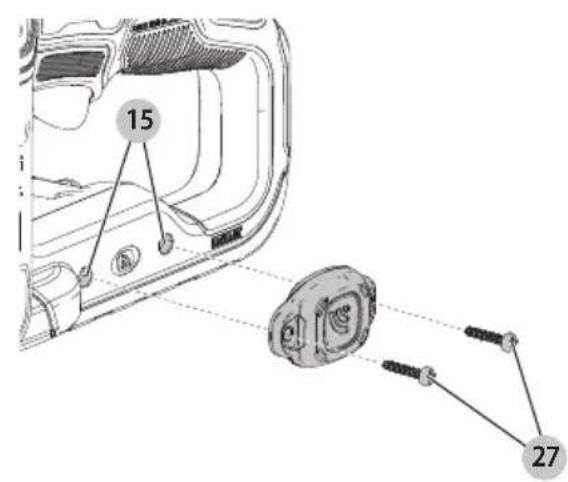
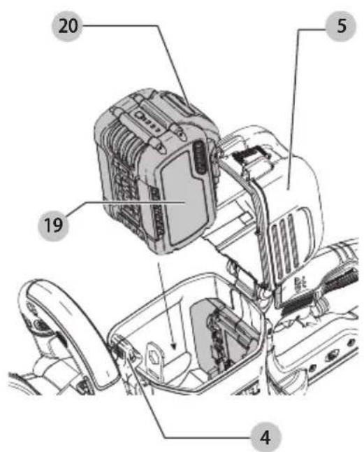
Fig. H Fig. I
natural_image
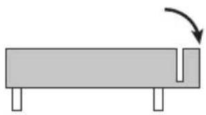
Simple diagram of a rectangular block with a curved arrow indicating rotation or movement (no text or symbols)Fig. J Fig. K
natural_image
Mechanical component diagram showing a rotating shaft and housing (no text or symbols)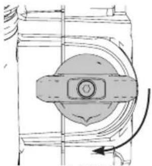
natural_image
Technical diagram of a mechanical component with no visible text or symbolsOPEN
OUVERTE
ABIERTA
CLOSED
FERMÉE
CERRADA
Fig. L Fig. M
natural_image
Technical line drawing of a mechanical device with a circular component and mounting base (no text or symbols)Fig. N Fig. O
natural_image
Diagram of a mechanical or agricultural system with concentric circular loops and directional arrows, no text or symbols present.Fig. P
WARNING: Read all safety warnings and all instructions. Failure to follow the warnings and instructions may result in electric shock, fire and/or serious injury.

WARNING: To reduce the risk of injury, read the instruction manual.
Intended Use
Your cut-off tool is designed for professional cutting applications. Only use wet cut method when cutting concrete. Dry cutting is possible when cutting metal.
DO nOT use in the presence of flammable liquids or gases.
Your cut-off tool is a professional power tool.
DO nOT let children come into contact with the tool.
Supervision is required when inexperienced operators use this tool.
Definitions: Safety Alert Symbols and Words
This instruction manual uses the following safety alert symbols and words to alert you to hazardous situations and your risk of personal injury or property damage.
DAJINGER: Indicates an imminently hazardous situation which, if not avoided, will result in death or serious injury.
WARNING: Indicates a potentially hazardous situation written, if not avoided, could result in death or serious injury.
CAUTION: Indicates a potentially hazardous situation which, if not avoided, may result in minor or moderate injury.
(### without word) Indicates a safety related message.
NOTICE: Indicates a practice not related to personal injury which, if not avoided, may result in property damage.
GENERAL POWER TOOL SAFETY WARNINGS
WARNING: Read all safety warnings, instructions, illustrations and specifications provided with this power tool. Failure to follow all instructions listed below may result in electric shock, fire and/or serious injury.
SAVE ALL WARNINGS AND INSTRUCTIONS FOR FUTURE REFERENCE.
The term "power tool" in the warnings refers to your mains-operated (corded) power tool or battery-operated (cordless) power tool.
1) Work Area Safety
a) Keep work area clean and well lit. Cluttered or dark areas invite accidents.
b) Do not operate power tools in explosive atmospheres, such as in the presence of flammable liquids, gases or dust. Power tools create sparks which may ignite the dust or fumes.
c) Keep children and bystanders away while operating a power tool. Distractions can cause you to lose control.
2) Electrical Safety
a) Power tool plugs must match the outlet. Never modify the plug in any way. Do not use any adapter plugs with earthed (grounded) power tools. Unmodified plugs and matching outlets will reduce risk of electric shock.
b) Avoid body contact with earthed or grounded surfaces, such as pipes, radiators, ranges and refrigerators. There is an increased risk of electric shock if your body is earthed or grounded.
c) Do not expose power tools to rain or wet conditions. Water entering a power tool will increase the risk of electric shock.
d) Do not abuse the cord. Never use the cord for carrying, pulling or unplugging the power tool. Keep cord away from heat, oil, sharp edges or moving parts. Damaged or entangled cords increase the risk of electric shock.
e) When operating a power tool outdoors, use an extension cord suitable for outdoor use. Use of a cord suitable for outdoor use reduces the risk of electric shock.
f) If operating a power tool in a damp location is unavoidable, use a ground fault circuit interrupter (GFCI) protected supply. Use of a GFCI reduces the risk of electric shock.
3) Personal Safety
a) Stay alert, watch what you are doing and use common sense when operating a power tool. Do not use a power tool while you are tired or under the influence of drugs, alcohol or medication. A moment of inattention while operating power tools may result in serious personal injury.
b) Use personal protective equipment. Always wear eye protection. Protective equipment such as a dust mask, non-skid safety shoes, hard hat, or hearing protection used for appropriate conditions will reduce personal injuries.
c) Prevent unintentional starting. Ensure the switch is in the off-position before connecting to power source and/or battery pack, picking up or carrying the tool. Carrying power tools with your finger on the switch or energizing power tools that have the switch on invites accidents.
d) Remove any adjusting key or wrench before turning the power tool on. A wrench or a key left attached to a rotating part of the power tool may result in personal injury.
e) Do not overreach. Keep proper footing and balance at all times. This enables better control of the power tool in unexpected situations.
f) Dress properly. Do not wear loose clothing or jewelry. Keep your hair, clothing and gloves away from moving parts. Loose clothes, jewelry or long hair can be caught in moving parts.
g) If devices are provided for the connection of dust extraction and collection facilities, ensure these are connected and properly used. Use of dust collection can reduce dust-related hazards.
English
h) Do not let familiarity gained from frequent use of tools allow you to become complacent and ignore tool safety principles. A careless action can cause severe injury within a fraction of a second.
4) Power Tool Use and Care
a) Do not force the power tool. Use the correct power tool for your application. The correct power tool will do the job better and safer at the rate for which it was designed.
b) Do not use the power tool if the switch does not turn it on and off. Any power tool that cannot be controlled with the switch is dangerous and must be repaired.
c) Disconnect the plug from the power source and/or remove the battery pack, if detachable, from the power tool before making any adjustments, changing accessories, or storing power tools. Such preventive safety measures reduce the risk of starting the power tool accidentally.
d) Store idle power tools out of the reach of children and do not allow persons unfamiliar with the power tool or these instructions to operate the power tool. Power tools are dangerous in the hands of untrained users.
e) Maintain power tools and accessories. Check for misalignment or binding of moving parts, breakage of parts and any other condition that may affect the power tool's operation. If damaged, have the power tool repaired before use. Many accidents are caused by poorly maintained power tools.
f) Keep cutting tools sharp and clean. Properly maintained cutting tools with sharp cutting edges are less likely to bind and are easier to control.
g) Use the power tool, accessories and tool bits etc. in accordance with these instructions, taking into account the working conditions and the work to be performed. Use of the power tool for operations different from those intended could result in a hazardous situation.
h) Keep handles and grasping surfaces dry, clean and free from oil and grease. Slippery handles and grasping surfaces do not allow for safe handling and control of the tool in unexpected situations.
5) Battery Tool Use and Care
a) Recharge only with the charger specified by the manufacturer. A charger that is suitable for one type of battery pack may create a risk of fire when used with another battery pack.
b) Use power tools only with specifically designated battery packs. Use of any other battery packs may create a risk of injury and fire.
c) When battery pack is not in use, keep it away from other metal objects, like paper clips, coins, keys, nails, screws or other small metal objects, that can make a connection from one terminal to another. Shorting the battery terminals together may cause burns or a fire.
d) Under abusive conditions, liquid may be ejected from the battery; avoid contact. If contact accidentally occurs, flush with water. If liquid contacts eyes, additionally seek medical help. Liquid ejected from the battery may cause irritation or burns.
e) Do not use a battery pack or tool that is damaged or modified. Damaged or modified batteries may exhibit unpredictable behavior resulting in fire, explosion or risk of injury.
f) Do not expose a battery pack or tool to fire or excessive temperature. Exposure to fire or temperature above 265 °F (130 °C) may cause explosion.
g) Follow all charging instructions and do not charge the battery pack or tool outside the temperature range specified in the instructions.
Charging improperly or at temperatures outside the specified range may damage the battery and increase the risk of fire.
6) Service
a) Have your power tool serviced by a qualified repair person using only identical replacement parts. This will ensure that the safety of the power tool is maintained.
b) Never service damaged battery packs. Service of battery packs should only be performed by the manufacturer or authorized service providers.
Additional Specific Safety Instructions for Cut-Off Machines
a) The guard provided with the tool must be securely attached to the power tool and positioned for maximum safety, so the least amount of wheel is exposed towards the operator. Position yourself and bystanders away from the plane of the rotating wheel. The guard helps to protect operator from broken wheel fragments and accidental contact with wheel.
b) Use only bonded reinforced wheels or diamond blades for your power tool. Just because an accessory can be attached to your power tool, it does not assure safe operation.
c) The rated speed of the accessory must be at least equal to the maximum speed marked on the power tool. Accessories running faster than their rated speed can break and fly apart.
d) Wheels must be used only for recommended applications. For example: do not grind with the side of cut-off wheel. Abrasive cut-off wheels are intended for peripheral grinding, side forces applied to these wheels may cause them to shatter.
e) Always use undamaged wheel flanges that are of correct diameter for your selected wheel. Proper wheel flanges support the wheel thus reducing the possibility of wheel breakage.
f) Do not use worn down reinforced wheels from larger power tools. Wheels intended for a larger
power tool are not suitable for the higher speed of a smaller tool and may burst.
g) The outside diameter and the thickness of your accessory must be within the capacity rating of your power tool. Incorrectly sized accessories cannot be adequately guarded or controlled.
h) The arbor size of wheels and flanges must properly fit the spindle of the power tool. Wheels and flanges with arbour holes that do not match the mounting hardware of the power tool will run out of balance, vibrate excessively and may cause loss of control.
i) Do not use damaged wheels. Before each use, inspect the wheels for chips and cracks. If power tool or wheel is dropped, inspect for damage or install an undamaged wheel. After inspecting and installing the wheel, position yourself and bystanders away from the plane of the rotating wheel and run the power tool at maximum no load speed for one minute. Damaged wheels will normally break apart during this test time.
j) Wear personal protective equipment. Depending on application, use face shield, safety goggles or safety glasses. As appropriate, wear dust mask, hearing protectors, gloves and shop apron capable of stopping small abrasive or workpiece fragments. The eye protection must be capable of stopping flying debris generated by various operations. The dust mask or respirator must be capable of filtering particles generated by your operation. Prolonged exposure to high intensity noise may cause hearing loss.
k) Keep bystanders a safe distance away from work area. Anyone entering the work area must wear personal protective equipment. Fragments of workpiece or of a broken wheel may fly away and cause injury beyond immediate area of operation.
1) Hold the power tool by insulated gripping surfaces only, when performing an operation where the cutting accessory may contact hidden wiring. Cutting accessory contacting a "live" wire may make exposed metal parts of the power tool "live" and could give the operator an electric shock.
m) Never lay the power tool down until the accessory has come to a complete stop. The spinning wheel may grab the surface and pull the power tool out of your control.
n) Do not run the power tool while carrying it at your side. Accidental contact with the spinning accessory could snag your clothing, pulling the accessory into your body.
o) Regularly clean the power tool's air vents. The motor's fan will draw the dust inside the housing and excessive accumulation of powdered metal may cause electrical hazards.
p) Do not operate the power tool near flammable materials. Sparks could ignite these materials.
Kickback and Related Warnings
Kickback is a sudden reaction to a pinched or snagged rotating wheel. Pinching or snagging causes rapid stalling of the rotating wheel which in turn causes the uncontrolled power tool to be forced in the direction opposite of the wheel's rotation at the point of the binding.
For example, if an abrasive wheel is snagged or pinched by the workpiece, the edge of the wheel that is entering into the pinch point can dig into the surface of the material causing the wheel to climb out or kick out. The wheel may either jump toward or away from the operator, depending on direction of the wheel's movement at the point of pinching. Abrasive wheels may also break under these conditions.
Kickback is the result of power tool misuse and/or incorrect operating procedures or conditions and can be avoided by taking proper precautions as given below.
a) Maintain a firm grip on the power tool and position your body and arm to allow you to resist kickback forces. Always hold front and rear handle for maximum control over kickback or torque reaction during start-up. The operator can
control torque reactions or kickback forces, if proper precautions are taken.
b) Never place your hand near the rotating accessory. Accessory may kickback over your hand.
c) Do not position your body in line with the rotating wheel. Kickback will propel the tool in direction opposite to the wheel's movement at the point of snagging.
d) Use special care when working corners, sharp edges etc. Avoid bouncing and snagging the accessory. Corners, sharp edges or bouncing have a tendency to snag the rotating accessory and cause loss of control or kickback.
e) Do not attach a saw chain, woodcarving blade, segmented diamond wheel with a peripheral gap greater than 10 mm or toothed saw blade. Such blades create frequent kickback and loss of control.
f) Do not "jam" the wheel or apply excessive pressure. Do not attempt to make an excessive depth of cut. Overstressing the wheel increases the loading and susceptibility to twisting or binding of the wheel in the cut and the possibility of kickback or wheel breakage.
g) When wheel is binding or when interrupting a cut for any reason, switch off the power tool and hold the power tool motionless until the wheel comes to a complete stop. Never attempt to remove the wheel from the cut while the wheel is in motion otherwise kickback may occur. Investigate and take corrective action to eliminate the cause of wheel binding.
h) Do not restart the cutting operation in the workpiece. Let the wheel reach full speed and carefully re-enter the cut. The wheel may bind, walk up or kickback if the power tool is restarted in the workpiece.
English
i) Support panels or any oversized workpiece to minimize the risk of wheel pinching and kickback. Large workpieces tend to sag under their own weight. Supports must be placed under the workpiece near the line of cut and near the edge of the workpiece on both sides of the wheel.
j) Use extra caution when making a "pocket cut" into existing walls or other blind areas. The protruding wheel may cut gas or water pipes, electrical wiring or objects that can cause kickback.
Additional Safety Information
- Use of accessories not specified in this manual is not recommended and may be hazardous. Use of power boosters that would cause the tool to be driven at speeds greater than its rated speed constitutes misuse.
- Do not use circular saw blades with this tool. Serious injury may result.
- Avoid bouncing the wheel or giving it rough treatment. If this occurs, stop the tool and inspect the wheel for cracks or flaws.
- Direct sparks away from operator, bystanders or flammable materials. Sparks may be produced while using a cut-off tool. Sparks may cause burns or start fires.
- Always use front handle. Make sure the front handle is securely tightened before use. The front handle should always be used to maintain control of the tool at all times.
- Never cut into area that may contain electrical wiring or piping. Serious injury may result.
- Clean out your tool often, especially after heavy use. Dust and grit containing metal particles often accumulate on interior surfaces and could create an electric shock hazard.
- Do not operate this tool for long periods of time. Vibration caused by tool action may be harmful to your hands and arms. Use gloves to provide extra cushion and limit exposure by taking frequent rest periods.
- Never use the weight of the tool to stop blade rotation.
- Never leave your cut-off machine unattended if it is in operating mode. When your cut-off machine is not in use, remove the battery pack, make sure the trigger switch is in the OFF position and lock-off button is engaged.
• Always wear sturdy boots with non-slip soles and heavy-duty work gloves when operating your cut-off machine. Heavy-duty gloves improve your grip and protect your hands.
• Always use NIOSH/OSHA approved respiratory protection when wet cutting below the recommended flow rate. - Consult and follow any federal, state or local laws or regulations with respect to dry and wet cutting.
- Never touch the rotating wheel with any part of your body.
-
When transporting the machine always make sure the lock-off button is in the locked position.
-
Remove the cutting wheel after use. The cutting wheel may suffer damage during transport.
- Never use a cutting wheel that is damaged, is untrue or vibrates.
- Never use your cut-off machine while standing on a ladder or scaffolding.
- Never cut above your shoulder height.
- Do not cut wood or any material from which the cutting wheel is not rated.
- Use the wet cut method when using a diamond blade whenever possible. The water can act as a lubricant and reduce the risk reactive forces.
- Use caution when reentering a cut. Do not push the cutting wheel into the cut at an angle as this can increase the risk on binding.
• Always be alert of anything that could cause the workpiece to close at the cut and pinch the cutting wheel. Always support the workpiece in a manner that results in the cut remaining open. Never make a cut that could result in binding of the cutting wheel.
WARNING: ALWAYS use safety glasses. Everyday eyeglasses are NOT safety glasses. Also use face or dust mask if cutting operation is dusty. ALWAYS WEAR CERTIFIED SAFETY EQUIPMENT:
• ANSI Z87.1 eye protection (CAN/CSA Z94.3),
• ANSI S12.6 (S3.19) hearing protection,
• NIOSH/OSHA/MSHA respiratory protection.
WARNING: Some dust created by power sanding, sanding, grinding, drilling, and other construction activities contains chemicals known to the State of California to cause cancer, birth defects or other reproductive harm. Some examples of these chemicals are:
- lead from lead-based paints,
• crystalline silica from bricks and cement and other masonry products, and
• arsenic and chromium from chemically-treated lumber.
Your risk from these exposures varies, depending on how often you do this type of work. To reduce your exposure to these chemicals: work in a well ventilated area, and work with approved safety equipment, such as those dust masks that are specially designed to filter out microscopic particles.
- Avoid prolonged contact with dust from power sanding, sawing, grinding, drilling, and other construction activities. Wear protective clothing and wash exposed areas with soap and water. Allowing dust to get into your mouth, eyes, or lay on the skin may promote absorption of harmful chemicals.
WARNING: Use of this tool can generate and/or depulse dust, which may cause serious and permanent respiratory or other injury. Always use NIOSH/OSHA approved respiratory protection appropriate for the dust exposure. Direct particles away from face and body.
WARNING: Always wear proper personal hearing protection that conforms to ANSI S12.6 (S3.19)
during use. Under some conditions and duration of use, noise from this product may contribute to hearing loss.
CAUTION: When not in use, place tool on its side can be stable surface where it will not cause a
tripping or falling hazard. Some tools with large battery packs will stand upright on the battery pack but may be easily knocked over.
- Air vents often cover moving parts and should be avoided. Loose clothes, jewelry or long hair can be caught in moving parts.
The label on your tool may include the following symbols. The symbols and their definitions are as follows:
V....volts
Hz ..... hertz
min ...... minutes
or DC.....direct current
Class I Construction (grounded)
.../min.....per minute
BPM.....beats per minute
☐...... Class II Construction (double insulated)
n_0 ...... no load speed
n ......rated speed
PSI..... pounds per square inch
earthing terminal
⚠️ ____ safety alert symbol
▲......visible radiation do not stare into the light
wearrespiratory protection
⑧ wear eye protection
○....wearhearing protection
readall
documentation
do not expose to rain
BATTERIES AND CHARGERS
The battery pack is not fully charged out of the carton. Before using the battery pack and charger, read the safety instructions below and then follow charging procedures outlined. When ordering replacement battery packs, be sure to include the catalog number and voltage.
READ ALL INSTRUCTIONS
Important Safety Instructions for All Battery Packs
WARNING: Read all safety warnings, instructions, and cautionary markings for the battery pack, charger and product. Failure to follow the warnings and instructions may result in electric shock, fire and/or serious injury.
- Do not charge or use the battery pack in explosive atmospheres, such as in the presence of flammable
liquids, gases or dust. Inserting or removing the battery pack from the charger may ignite the dust or fumes.
- NEVER force the battery pack into the charger. DO NOT modify the battery pack in any way to fit into a non-compatible charger as battery pack may rupture causing serious personal injury. Consult the chart at the end of this manual for compatibility of batteries and chargers.
• Charge the battery packs only in DEWALT chargers.
• DO NOT splash or immerse in water or other liquids.
- DO NOT allow water or any liquid to enter battery pack.
- Do not store or use the tool and battery pack in locations where the temperature may reach or exceed 104 °F (40 °C) (such as outside sheds or metal buildings in summer). For best life store battery packs in a cool, dry location.
NOTE: Do not store the battery packs in a tool with the trigger switch locked on. Never tape the trigger switch in the ON position.
- Do not incinerate the battery pack even if it is severely damaged or is completely worn out. The battery pack can explode in a fire. Toxic fumes and materials are created when lithium-ion battery packs are burned.
- Do not expose a battery pack or appliance to fire or excessive temperature. Exposure to fire or temperature above 265 °F (130 °C) may cause explosion.
- Follow all charging instructions and do not charge the battery pack or appliance outside of the temperature range specified in the instructions. Charging improperly or at temperatures outside of the specified range may damage the battery and increase the risk of fire.
- If battery contents come into contact with the skin, immediately wash area with mild soap and water. If battery liquid gets into the eye, rinse water over the open eye for 15 minutes or until irritation ceases. If medical attention is needed, the battery electrolyte is composed of a mixture of liquid organic carbonates and lithium salts.
- Contents of opened battery cells may cause respiratory irritation. Provide fresh air. If symptoms persist, seek medical attention.
- Battery liquid may be flammable if exposed to spark or flame.
- Never attempt to open the battery pack for any reason. If the battery pack case is cracked or damaged, do not insert into the charger. Do not crush, drop or damage the battery pack. Do not use a battery pack or charger that has received a sharp blow, been dropped, run over or damaged in any way (e.g., pierced with a nail, hit with a hammer, stepped on). Damaged battery packs should be returned to the service center for recycling.
Storage Recommendations
The best storage place is one that is cool and dry, away from direct sunlight and excess heat or cold. Store the fully charged battery pack out of the charger.
Battery Pack Cleaning Instructions
Dirt and grease may be removed from the exterior of the battery pack using a cloth or soft non-metallic brush. Do not use water or any cleaning solutions.
Fuel Gauge Battery Packs (Fig. B)
Some battery packs include a fuel gauge. When the fuel gauge button is pressed and held, the LED lights will indicate the approximate level of charge remaining. This does not indicate tool functionality and is subject to variation based on product components, temperature, and end-user application.
Transportation
WARNING: Fire hazard. Do not store, carry, or transport the battery pack so that metal objects can contact exposed battery terminals. For
example, do not place the battery pack in aprons, pockets, tool boxes, product kit boxes, drawers, etc., with loose nails, screws, keys, coins, hand tools, etc. When transporting individual battery packs, make sure that the battery terminals are protected and well insulated from materials that could contact them and cause a short circuit. NOTE: Li-ion battery packs should not be put in checked baggage on airplanes and must be properly protected from short circuits if they are in carry-on baggage.
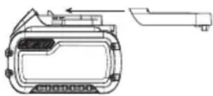
Shipping the DEWALT FLEXVOLT® Battery Pack
The DEWALT FLEXVOLT® battery pack has a battery cap that should be used when shipping the battery pack.
natural_image
Technical line drawing of a device casing with mounting bracket and side panel (no text or symbols)Attach the cap to the battery pack to ready it for shipping. This converts the battery pack to three separate 20V batteries. The three batteries have the Watt hour rating labeled "Shipping" on the battery pack. If shipping without the cap or in a tool, the pack is one battery at the Watt hour rating labeled "Use".
Example battery pack label:
USE: 120 Wh SHIPPING: 3 x 40 Wh
In this example, the battery pack is three batteries with 40 Watt hours each when using the cap. Otherwise, the battery pack is one battery with 120 Watt hours.
The RBRC® Seal
Please take your spent battery packs to an authorized DEWALT service center or to your local retailer for recycling. In some areas, it is illegal to place spent battery packs in the trash. You may also contact your local recycling center for information on where to drop off the spent battery pack. Do not place in curbside recycling. For more information visit www.call2recycle.org, or call the toll free number in the RBRC® Seal.
RBRC ^® is a registered trademark of Call 2 Recycle, Inc.

Important Safety Instructions for All Battery Chargers
WARNING: Read all safety warnings, instructions, and cautionary markings for the battery pack, charger and product. Failure to follow the warnings and instructions may result in electric shock, fire and/or serious injury.
- DO NOT attempt to charge the battery pack with any chargers other than a DEWALT charger. DEWALT chargers and battery packs are specifically designed to work together.
• These chargers are not intended for any uses other than charging DEWALT rechargeable battery packs. Charging other types of battery packs may cause them to overheat and burst, resulting in personal injury, property damage, fire, electric shock or electrocution. - Do not expose the charger to rain or snow.
- Do not allow water or any liquid to enter charger.
- Pull by the plug rather than the cord when disconnecting the charger. This will reduce the risk of damage to the electric plug and cord.
- Make sure that the cord is located so that it will not be stepped on, tripped over or otherwise subjected to damage or stress.
- Do not use an extension cord unless it is absolutely necessary. Use of improper extension cord could result in risk of fire, electric shock or electrocution.
- When operating a charger outdoors, always provide a dry location and use an extension cord suitable for outdoor use. Use of a cord suitable for outdoor use reduces the risk of electric shock.
- An extension cord must have adequate wire size (AWG or American Wire Gauge) for safety. The smaller the gauge number of the wire, the heavier the cord and thus the greater its capacity. An undersized cord will cause a drop in line voltage resulting in loss of power and overheating. The following table shows the correct size to use depending on total length of all extension cords plugged together, and nameplate ampere rating. If in doubt, use the next heavier gauge.
Minimum Gauge for Cord Sets
| Volts | Total Length of Cord in Feet (meters) | ||||
| 120V 25 (7.6) | 50 (15.2) 100 | (30.5) 150 (45.7) | |||
| Ampere Rating | American Wire Gauge | ||||
| More Than Not More Than | |||||
| 0 6 18 | 16 16 14 | ||||
| 6 10 18 | 16 14 12 | ||||
| 10 12 16 | 16 14 12 | ||||
| 12 16 14 | 12 Not Recommended | ||||
- Do not place any object on top of the charger or place the charger on a soft surface that might block the ventilation slots and result in excessive internal heat.
Place the charger in a position away from any heat source. The charger is ventilated through slots in the top and the bottom of the housing.
- Do not operate the charger with a damaged cord or plug. Have them replaced immediately.
- Do not operate the charger if it has received a sharp blow, been dropped or otherwise damaged in any way. Take it to an authorized service center.
- Do not disassemble the charger; take it to an authorized service center when service or repair is required. Incorrect reassembly may result in a risk of electric shock, electrocution or fire.
- The charger is designed to operate on standard 120V household electrical power. Do not attempt to use it on any other voltage. This does not apply to the vehicular charger.
- Foreign materials of a conductive nature, such as, but not limited to, grinding dust, metal chips, steel wool, aluminum foil or any buildup of metallic particles should be kept away from the charger cavities and ventilation slots.
• Always unplug the charger from the power supply when there is no battery pack in the cavity.
Charging a Battery (Fig. C)
- Plug the charger into an appropriate outlet.
- Insert and fully seat battery pack 19. The red charging light(s) will continuously blink while charging.
- Charging is complete when the red charging light(s) remain(s) continuously ON. Battery pack can be left in charger or removed. Some chargers require the battery pack release button to be pressed for removal.
WARNING: Only charge batteries in air temperature over 10^ F ( 4.5^ C) and below 104^ F ( +40^ C).
- Charger will not charge a faulty battery pack, which may be indicated by the charging light(s) staying OFF. Take charger and battery pack to an authorized service center if light(s) stay(s) OFF.
NOTE: Refer to label near charging light(s) on charger for blink patterns. Older chargers may have additional information and/or may not have a yellow indicator light.
NOTE: To remove the battery pack, some chargers require the battery pack release button to be pressed.
Hot/Cold Pack Delay
When the charger detects a battery pack that is too hot or too cold, it automatically starts a Hot/Cold Pack Delay, suspending charging until the battery pack has reached an appropriate temperature. The charger then automatically switches to the pack charging mode. This feature ensures maximum battery pack life.
A cold battery pack may charge at a slower rate than a warm battery pack.
The hot/cold pack delay will be indicated by the red light(s) continuing to blink but with the yellow light continuously ON. Once the battery pack has reached an appropriate temperature, the yellow light will turn OFF and the charger will resume the charging procedure.
DCB118 and DCB1112 Chargers
The DCB118 and DCB1112 chargers are equipped with an internal fan designed to cool the battery pack. The fan will turn on automatically when the battery pack needs to be cooled.
Never operate the charger if the fan does not operate properly or if ventilation slots are blocked. Do not permit foreign objects to enter the interior of the charger.
Electronic Protection System
Li-Ion tools are designed with an Electronic Protection System that will protect the battery pack against overloading, overheating or deep discharge. The tool will automatically turn off and the battery pack will need to be recharged.
Important Charging Notes
- Longest life and best performance can be obtained if the battery pack is charged when the air temperature is between 65 ^ - 75 ^ ( 18 ^ - 24 ^ ). DO NOT charge when the battery pack is below +40 ^ (+4.5 ^ ), or above +104 ^ (+40 ^ ). This is important and will prevent serious damage to the battery pack.
- The charger and battery pack may become warm to the touch while charging. This is a normal condition, and does not indicate a problem. To facilitate the cooling of the battery pack after use, avoid placing the charger or battery pack in a warm environment such as in a metal shed or an uninsulated trailer.
- If the battery pack does not charge properly:
a. Check operation of receptacle by plugging in a lamp or other appliance;
b. Check to see if receptacle is connected to a light switch which turns power off when you turn out the lights;
c. If charging problems persist, take the tool, battery pack and charger to your local service center.
- You may charge a partially used pack whenever you desire with no adverse effect on the battery pack.
Charger Cleaning Instructions
WARNING: Shock hazard. Disconnect the charger from the AC outlet before cleaning. Dirt and grease may be removed from the exterior of the charger using a cloth or soft non-metallic brush. Do not use water or any cleaning solutions.
Wall Mounting
Some DEWALT chargers are designed to be wall mountable or to sit upright on a table or work surface. If wall mounting, locate the charger within reach of an electrical outlet, and away from a corner or other obstructions which may impede air flow. Use the back of the charger as a template for the location of the mounting screws on the wall. Mount the charger securely using drywall screws (purchased separately) at least 1" (25.4 mm) long, with a screw head diameter of 0.28–0.35" (7–9 mm), screwed into wood to an optimal depth leaving approximately 7/32" (5.5 mm) of the screw exposed. Align the slots on the back of the charger with the exposed screws and fully engage them in the slots.
SAVE THESE INSTRUCTIONS FOR FUTURE USE
ASSEMBLY AND ADJUSTMENTS
WARNING: To reduce the risk of serious personal injury, turn unit off and remove the battery pack before making any adjustments or removing/installing attachments or accessories. An accidental start-up can cause injury.
SPECIFICATIONS
DCs692
| Blade diameter 9" (230 mm) |
| Arbor size 7/8" (22.2 mm) |
| RPM 6600 |
Lock-Off Button (Fig. A)
Your cut-off tool is equipped with a lock-off button 3. To lock the trigger switch in the OFF position, push the lock-off button from the left side of the tool. To unlock the trigger switch, push the lock-off button from the right side of the tool.
Spindle Lock Button (Fig. A)
The spindle lock button 13 is used to lock the arbor screw 11 when changing accessories.
- To engage the spindle lock button, remove the battery pack and make sure trigger switch is in the OFF position and lock-off button is engaged.
- Depress the spindle lock button and turn the wheel and spindle until the lock button engages the spindle.
- Use supplied wrench 6 to unscrew the arbor screw 11 and remove or mount accessories. Spindle threads are right hand.
Installing Abrasive and Diamond Wheels (Fig. A, D)

NING: Install only one blade.
- Lay unit on a firm surface, with the arbor screw 11 facing upward.
- Using supplied 1/2" (13 mm) open end wrench 6 (located in the battery compartment), remove arbor screw 11, outer clamp washer 21 and used wheel 22 if one is installed. Hold arbor screw 11 from turning with spindle lock button 13. Spindle threads are right hand.
- The inner clamp washer 23 is held in place with a double D shaft and retaining ring.
- Slip wheel over spindle 25. Slip on outer clamp washer. Start threading on arbor screw which will self align outer clamp washer.
iIMPORTAnT: Make sure the diamond blade is installed with the correct rotation, as marked on the blade rotation indicator 12. - Engage spindle lock button and tighten screw firmly with wrench. Do not over-tighten arbor screw.
- Turn wheel by hand to ensure it is properly centered. The wheel should not hit the shoe or guard. The screw and flanges should be tight.
CAUTION: Only use 9" (230 mm) Type 1/41 wheels with 1/8" (22.2 mm) arbor hole with this tool. Never force a wheel onto the machine or alter the size of the arbor hole.
Replacing Worn Clamp Washers (Fig. D)
WARNING: Replace clamp washers as they wear. They may become sharp with extended use.
- Remove the arbor screw 11, outer clamp washer 21 and used wheel 22 if one is installed as described in Installing Abrasive and Diamond Wheels.
- To remove the inner clamp washer 23, first remove the retaining ring that holds the inner clamp washer to the double D shaft.
- Remove the inner clamp washer and replace with a new one. Orient the inner clamp washer with the depressed center section toward the blade. Make sure the new inner clamp washer is secure with the retaining ring in place.
- Install the wheel 22, new outer clamp washer 21, and arbor screw 11 as described in Installing Abrasive and Diamond Wheels.
Adjusting the Guard Angle (Fig. E)
WARNING: Do not use guard rotation handle to hand tool while cutting. Guard rotation handle is only used for adjustment of the guard while tool is not in use.
CAUTION: Guard may be hot. Use guard handle to rotate guard.
WARNING: Always make sure the guard is properly engaged before starting the machine.
You can adjust the angle of the guard.
- To adjust the angle of the guard, pull back the guard rotation release lever 14 and hold it.
- Grasp the guard 9 firmly by guard rotation handle 10 and rotate to desired angle.
- Release the guard rotation release lever and make sure it engages, locking the guard in place. If the guard rotation release lever doesn't engage, rotate the guard slightly until the guard rotation release lever returns to the locked position.
DEWALT Bluetooth® Tool Tag Ready (Fig. A)
Optional Accessory
WARNING: Read instruction manual for the DEWALT Bluetooth® Tool Tag.
WARNING: Remove battery from tool before installing the DWALT Bluetooth® Tool Tag.
WARNING: When installing or replacing the DEWALT Bio-oth® Tool Tag, use only the screws provided. Be sure to securely tighten the screws.
Your tool comes with mounting holes 15 and fasteners 27 for installing a DEWALT Bluetooth® Tool Tag (DCE041). You will need a T15 torx bit tip to install the tag. Screw torque should be between 0.8 and 1.2 Nm (7.1 to 10.6 in-lbs). The DEWALT Tool Tag is designed for tracking and locating professional power tools, equipment, and machines using
the DEWALT Tool Connect™ app. For proper installation of the DEWALT Tool Tag, refer to the DEWALT Tool Tag manual.
To learn more, visit:
www.DEWALT.com/en-us/jobsite-solutions/tool-connect
OPERATION
WARNING: To reduce the risk of serious personal injury, turn unit off and remove the battery pack before making any adjustments or removing/installing attachments or accessories. An accidental start-up can cause injury.
Installing and Removing the Battery Pack (Fig. G)
NOTE: For best results, make sure your battery pack is fully charged. Use only DEWALT FLEXVOLT™ batteries with this cut-off machine.
Unlock battery door 5 by moving battery door latch 4 towards the front of the tool and open as shown in Figure G.
To install the battery pack 19 into the tool, align the battery pack with the rails inside the tool and slide it in until the battery pack is firmly seated. Ensure that it does not disengage.
Close the battery door 5, and push the battery door latch 4 toward the back of the tool to lock the battery door.
To remove the battery pack from the tool, unlatch and open the battery door. Then press the battery release button 20 and firmly pull the battery pack out of the tool. Insert it into the charger as described in Charging a Battery.
Do not leave the battery door open.
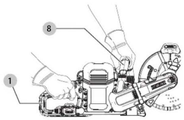
Proper Hand Position (Fig. H)
WARNING: To reduce the risk of serious personal injury, ALWAYS use proper hand position as shown.
WARNING: To reduce the risk of serious personal injury, ALWAYS hold securely in anticipation of a sudden reaction.
WARNING: Never use the cut-off machine with one hand. Always grip the cut-off machine firmly with both hands.
WARNING: Make sure the handles and grips of your cut-off machine are secure and free of grease and/or moisture.
Proper hand position for both left- and right-handed users requires your right hand on the rear handle 1 and your left hand on the front handle 8.
Wireless Tool Control (Fig. A)
CAUTION: Read all safety warnings, instruction and specifications of the appliance which is paired with the tool.
Your tool is equipped with a Wireless Tool Control transmitter which allows your tool to be wirelessly paired with another Wireless Tool Control device, such as a DFWALT dust extractor.
To pair your tool using Wireless Tool Control, depress the trigger switch 2 and the Wireless Tool Control pairing button on the separate device. An LED on the separate
device will let you know when your tool has been successfully paired.
Heavy Load Indicator LED (Fig. A)
The heavy load indicator LED 7 will illuminate as a warning when the tool is being pushed too hard. Continuing to use the tool after the LED is lit could cause the tool to shut down or reduce run time.
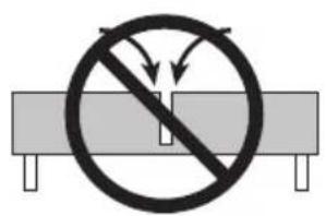
Reducing the Risk of Kickback (Fig. I)
WARNING: Reactive forces may occur at any time that cutting wheel is in motion.
WARNING: To reduce the risk of kickback, avoid cutting with the upper quadrant of the cutting wheel whenever possible. Be extremely mindful of binding or pinching of the cutting wheel in this area as it can cause severe reactive forces resulting in kickback.
• Always be alert to any potential movement that could cause the material being cut to close and pinch the cutting wheel.
- Proper support of the material will ensure the cut stays open during the cut. If you cannot properly support the material, do not use a cut-off machine to make your cut.
- Always support exposed pipe in the ground so that it is stable and is able to support weight. Use additional support closer to the area to be cut to prevent the pipe from sagging and pinching the cutting wheel.
- Material that is under stress could shift when it is cut. Uneven pipe beds could exert stress.
• Always make sure the section of material being removed is also supported. After the first cut is made you may have to move supports or add additional support to ensure both sides of the material are evenly supported.
- Be aware of weakened work areas that could shift or slide causing your supports to move.
Making Cuts with a Cut-Off Machine
CAUTION: Before attempting to start, grasp tool firmly with both hands before lifting.
WARNING: Cut-off saw not intended for surface gathering or other applications where side loading of the blade is encountered.
WARNING: Edge cutting can be performed only with wheels that are designed and specified for this purpose. Protect yourself during edge cutting by directing the open side of the guard away from you, the operator.
WARNING: Wheels used for cutting may break or kick back if they bend or twist while the tool is being used to do cut-off work.
WARNING: Always be alert for gyroscopic forces that can be generated by a rapidly spinning cutting wheel. Moving the cut-off machine sideways can create a gyroscopic force, causing the operator to experience an unexpected perpendicular change in direction.
Wet Cut Method (Fig. A, J, K)
CAUTION: Close battery door and securely latch it closed before using any water.
CAUTION: Never use the saw over head. When using water limit cutting to the horizontal position to reduce the risk of water entering the tool.
WARNING: Wet cut method is to be used only with a diamond blade.
WARNING: The recommended flow rate should be at least 20 fl. oz. (0.6 liters) per minute. Cutting at a flow rate less than recommended or cutting for more than two consecutive hours requires use of NIOSH/OSHA approved respiratory protection for the operator and any bystanders.
WARNING: Maximum supplied water pressure not to exceed 60 PSI (4.1 bar).
WARNING: Makes sure that water does not flow onto the abrasive wheel while the cut-off machine is not in use. The cutting wheel will absorb water which will affect the balance.
NOTICE: Before using the wet cut method, make sure water will not damage the material being cut or surrounding property.
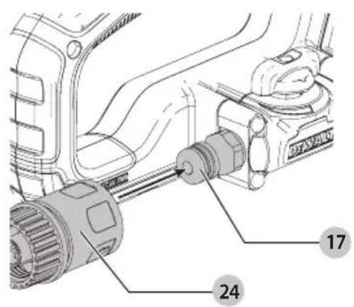
Attaching the Water Supply
- Attach the water supply to the quick water connector 24.
- Attach the quick water connector to the water inlet 17.
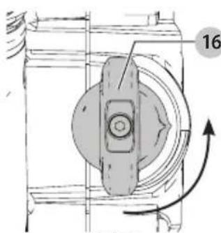
- To regulate the water flow, slowly rotate the water valve 16 towards to open position until desired flow is reached as shown in Figure K. To stop the flow of water, rotate the water valve to the closed position.
- Proceed to cut as described in Making a Cut below.
- After finishing your cuts, run the machine for 3–5 seconds with the water valve closed to remove any residual water from the cutting wheel.
Removing the Water Supply
- Turn off and depressurize water system.
- Make sure the trigger switch 2 is in the OFF position and lock-off button 3 is engaged.
- Close the water valve 16.
- Disconnect the quick water connector 24 from the water inlet 17.
Making a Cut
WARNING: Always make sure the guard is in place and set for the type of cut you are making.
WARNING: Always use your cut-off machine so that the operator and bystanders are not endangered by potential airborne particles of material being cut, sparks, or pieces of damaged cutting wheels.
DANGER: To reduce the risk of serious or fatal injury, DO NOT change direction during the cut. A change in direction may produce a high torsional load on the cutting wheel and cause it to bind or break.
CAUTION: Wear gloves when cutting metal.
- Mark a cutting line on the material to be cut.
-
Grasp rear handle 1 and front handle 8 firmly.
-
Line up wheel with cutting line. Be sure nothing is near or in line with the wheel.
- To turn the tool on, push the lock-off lever 18 toward the back of the tool, then depress the trigger switch 1. Wait for the blade to reach full speed, then slowly feed wheel into work with firm pressure, working along the cutting line. Do not force the tool. Cut only as deep as needed to reduce the amount of dust produced. For maximum efficiency and wheel life, keep the wheel speed high. To maintain control of the cut-off machine, release pressure as you near the end of your cut.
- To stop tool, release trigger switch 2.
- Set the lock-off button 3 to the locked position and make sure the cutting wheel has come to a complete stop before setting the cut-off machine down.
NOTE: Denser and thicker material should be cut in several passes. The maximum depth of cut of each pass should not exceed 1.0" (25.4 mm).
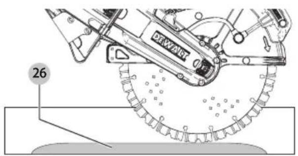
Cutting Slabs (Fig. L, M)
WARNING: Before making any cuts, make sure the slab is properly secured on a non-slip surface.
- Cut a guiding groove along a marked cutting line.
- Cut deeper into the slab, never exceeding the maximum depth of cut of 3.25" (83 mm), and leaving a ridge of uncut material 26 as shown on Fig. L.
- Cut through the slab at each end to ensure the slab does not chip.
- Break the slab.
NOTE: Curves must be made into the slab using several straight cuts as shown in Fig. M, always making sure that the cutting wheel does not become wedged.
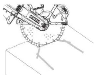
Cutting Pipe (Fig. N, O)
WARNING: Before making any cuts, make sure the pipe is properly secured on a non-slip surface.
WARNING: Pipe may break at any time during the cut. Take precautions to maintain control of the tool and avoid falling debris.
If the outer diameter of the pipe is smaller than the maximum cutting depth
- Make one cut straight down, starting at the top of the pipe through to the bottom of the pipe.
If the outer diameter of the pipe is larger than the maximum cutting depth
Several cuts are needed on larger pipes and it is important to make the cuts in the proper sequence.
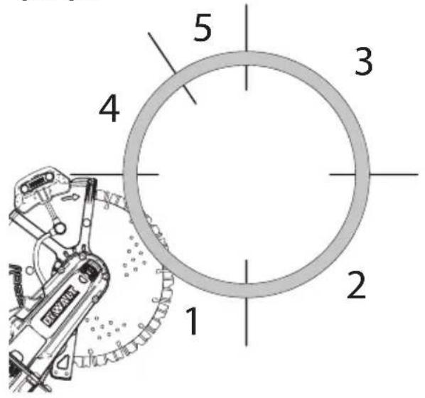
If the pipe is in-ground and can not be rolled, make the following sequence of cuts
- Cut a guiding groove along a marked cutting line making sure to avoid any metal reinforcements if possible.
- Start at the bottom of the pipe and use only the front and upper part of the cutting wheel. This will reduce the risk of kickback or pinching.
- Using only the front and upper part of the cutting wheel, make a cut on the oppsite lower side of the pipe.
-
Make a lateral cut on the top half of the pipe.
-
Make a second lateral cut on the opposite side of the top half.
IMPORTANT: To keep the pipe from pinching the cutting wheel, make sure not to cut into the area of the final cut.
- Make sure all the top and bottom cuts are complete when making the final top cut.
IMPORTANT: Always make the final cut from the top of the pipe. If the pipe is properly supported, this will reduce the risk of pinching the cutting wheel. If any pinching does occur it will be at the bottom of the cutting wheel resulting in pull-away but not kickback.
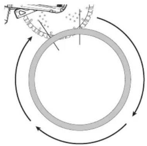
If the pipe is free and can be rolled, make the following sequence of cuts
- Secure the pipe on a non-slip surface.
- Using only the bottom part of the cutting wheel, make a cut in the upper part of the pipe.
- Roll the pipe and repeat steps 1 and 2 until the cut is complete.
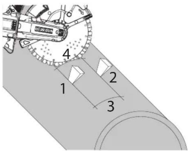
Cutting a Recess in Concrete Pipe (Fig. P)
WARNING: Before making any cuts, make sure the pipe is properly secured on a non-slip surface.
Several cuts are needed to make a recess cut in concrete pipe and it is important to make the cuts in the proper sequence.
- First make two cuts along the length of the pipe. Always make an axial cut to avoid pinching of the cutting wheel.
- Insert wedges into the cuts.
- Make the third and fourth cuts to complete the recess.
- If the severed part remains after all four cuts are made, do not make any more cuts. Break the severed part out
Applications
WARNING: NEVER cut magnesium with this tool. Magnesium particles may ignite causing personal injury.
• 1/8" (3 mm) max. gauge sheet metal
• Concrete, cinder blocks and bricks
• Roofing tiles (terracotta or similar)
- Curb stone/pavers
- Asphalt
- Reinforcing rod; generally under 1" (25.4 mm) diameter
• 1/8" (3 mm) diameter concrete wire mesh
• Corrugated floor and ceiling form (concrete forms)
• Electrical conduit 1/8" (3 mm) wall thickness
- 1/8" (3 mm) max. thick structural forms such as channel, angles, plate, etc.
NOTE: The cutting of materials heavier than those listed above are not recommended due to the possibility of tool damage.
MAINTENANCE
WARNING: To reduce the risk of serious personal injury, turn unit off and remove the battery pack before making any adjustments or removing/
installing attachments or accessories. An accidental start-up can cause injury.
Your DEWALT power tool has been designed to operate over a long period of time with a minimum of maintenance. Continuous satisfactory operation depends upon proper tool care and regular cleaning.
Maintenance Schedule
Before use Daily/After work
| Clean machine X |
| Check/clean handles X |
| Check intake port X |
| Check battery X |
| Check battery compartment X |
| Check water intake X |
| Check cutting wheel X |
| Check guide plate X |
Cleaning
WARNING: Blow dirt and dust out of all air vents with dry air at least once a week. To minimize the risk of eye injury, always wear ANSI Z87.1 approved eye protection when performing this procedure.
WARNING: Never use solvents or other harsh chemicals for cleaning the non-metallic parts of the tool. These chemicals may weaken the plastic materials used in these parts. Use a cloth dampened only with water and mild soap. Never let any liquid get inside the tool; never immerse any part of the tool into a liquid.
Accessories
WARNING: Use only diamond segmented wheels with a maximum peripheral gap between segments and a negative rake angle.
WARNING: Since accessories, other than those offered by DEWALT, have not been tested with this product, use of such accessories with this tool could be hazardous. To reduce the risk of injury, only DEWALT recommended accessories should be used with this product.
WARNING: Accessories must be rated for at least the speed recommended on the tool warning label. Wheels and other accessories running over rated speed can fly apart and cause injury. Accessory ratings must always be above tool speed as shown on tool nameplate.
WARNING: Handle and store all abrasive wheels orally to prevent damage from thermal shock, heat, mechanical damage, etc. Store in a dry protected area free from high humidity, freezing temperatures or extreme temperature changes.
A bonded reinforced wheel contains abrasive grains which are held tightly together by a bonding and are reinforced with a woven material.
Recommended accessories for use with your tool are available at extra cost from your local dealer or authorized service center. If you need assistance in locating any accessory, please contact DEWALT Industrial
ENGLISH
Tool Co., 701 East Joppa Road, Towson, MD 21286, call 1-800-4-DEWALT (1-800-433-9258) or visit our website: www.dewalt.com.
Register Online
Thank you for your purchase. Register your product now for:
- WARRANTY SERVICE: Registering your product will help you obtain more efficient warranty service in case there is a problem with your product.
- CONFIRMATION OF OWNERSHIP: In case of an insurance loss, such as fire, flood or theft, your registration of ownership will serve as your proof of purchase.
• FOR YOUR SAFETY: Registering your product will allow us to contact you in the unlikely event a safety notification is required under the Federal Consumer Safety Act. - Register online at www.dewalt.com.
Three Year Limited Warranty
For warranty terms, go to https://www.dewalt.com/Legal/Warranty/3-Year-Limited-Warranty.
To request a written copy of the warranty terms, contact: Customer Service at DEWALT Industrial Tool Co., 701 East Joppa Road, Towson, MD 21286 or call 1-800-4-DEWALT (1-800-433-9258).
LATIN AMERICA: This warranty does not apply to products sold in Latin America. For products sold in Latin America, see country specific warranty information contained in the packaging, call the local company or see website for warranty information.
FREE WARNING LABEL REPLACEMENT: If your warning labels become illegible or are missing, call 1-800-4-DeWALT (1-800-433-9258) for a free replacement.
TROUBLESHOOTING
BE SURE TO FOLLOW SAFETY RULES AND INSTRUCTIONS
For assistance with your product, visit our website at www.dewalt.com for a list of service centers, or call DEWALT at 1-800-4-DEWALT (1-800-433-9258).
PROBLEM POSSIBLE CAUSE SOLUTION
| Machine will not start. Battery pack not installed properly. Check battery pack installation. | ||
| Battery pack not charged. Check battery pack charging requirements. | ||
| Battery pack too hot/cold. Allow battery to cool down or warm up. | ||
| Internal components too hot. Allow machine to cool down. | ||
| Machine shuts off abruptly. Battery pack has reached its maximum thermal limit. | Allow battery pack to cool down. | |
| Reduced run time. Battery is not completely charged. Charge battery. | ||
| Life of the battery has been reached. | Replace with a new DeWALT FLEXVOLT ^TM battery. | |
| Battery pack will not charge. | Battery pack not inserted into charger. | Insert battery pack into charger until LED illuminates. |
| Charger not plugged in. Plug charger into a working outlet. Refer to Important Charging Notes for more details. | ||
| Surrounding air temperature too hot or too cold. Move charger and battery pack to a surrounding air temperature of approximately 65 °F – 75 °F (18 °C– 24 °C). | ||
| Frayed edges or tears on the cutting wheel. | Cutting wheel wobbling. | Replace with a new cutting wheel. |
| Cutting wheel is blunt. | Replace with a new cutting wheel. | |
| Built-up edges on the cutting wheel. | Dress the cutting wheel by briefly cutting in abrasive material. | |
| Cutting wheel wanders off the cutting line. | Cutting wheel wobbling. | Replace with a new cutting wheel. |
| Cutting wheel is blunt. | Replace with a new cutting wheel. | |
| Cutting wheel is not properly installed. | Mount cutting wheel correctly. Refer to Installing Abrasive and Diamond Wheels. | |
| Wear on the side of the cutting wheel. | Surface grinding. | Do not surface grind with the cutting wheel. |
| Reduced or no cutting performance. | Cutting wheel is blunt. | Replace with a new cutting wheel. |
| Built-up edges on the cutting wheel for stone. | Dress the cutting wheel for stone by briefly cutting in abrasive material. Use a new cutting wheel for cutting asphalt. | |
| Cutting wheel is not properly installed. | Mount cutting wheel correctly. Refer to Installing Abrasive and Diamond Wheels. | |
| Cutting material for which the cutting wheel is not rated. | Use the proper cutting wheel. | |
| Chipping or cracking in the wheel core. | Overload. | Replace with a new cutting wheel. |
| Sparking. | Built-up edges on the cutting wheel for stone. | Dress the cutting wheel for stone by briefly cutting in abrasive material. Use a new cutting wheel for cutting asphalt. |
| Heavy load indicator LED illuminated. | Too much force on the tool. | Reduce force. |
natural_image
Technical line drawing of a mechanical device with no visible text or symbolsFixez le
www.DEWALT.com/en-us/jobsite-solutions/tool-connect
FONCTIONNEMENT
PROBLÈME CAUSE POSSIBLE SOLUTION
natural_image
Technical line drawing of a mechanical component with no visible text or symbolswww.DEWALT.com/en-us/jobsite-solutions/tool-connect
OPERACIÓN
Eje Central Lázaro Cárdenas No. 18 - Local (55) 5588 9377 D, Col. Obrera
MERIDA, YUC
Calle 63 #459-A - Col. Centro (999) 928 5038
MONTERREY, N.L.
Av. Francisco I. Madero 831 Poniente - Col. (818) 375 23 13 Centro
PUEBLA, PUE
17 Norte #205 - Col. Centro (222) 246 3714
QUERETARO, QRO
Av. San Roque 274 - Col. San Gregorio (442) 2 17 63 14
SAN LUIS POTOSI, SLP
Col. Santa Fe Alvaro Obregon,
Ciudad de Mexico, Mexico.
C.P 01210
TEL(52) 55 53267100 R.F.C.BDE8106261W7
Registro en Línea
* Maximum initial battery voltage (measured without a workload) is 20, 60 or 120 volts. Nominal voltage is 18, 54 or 108. (120V Max* is based on using 2 DEWALT 60V Max* lithium-ion batteries combined.)
NOTE: The Bluetooth® word mark and logos are registered trademarks owned by the Bluetooth®, SIG, Inc. and any use of such marks by DEWALT is under license. Other trademarks and trade names are those of their respective owners.
NING: Use of any other battery packs may create a risk of injury and fire.


- Composants
- Intended Use
- Definitions: Safety Alert Symbols and Words
- GENERAL POWER TOOL SAFETY WARNINGS
- SAVE ALL WARNINGS AND INSTRUCTIONS FOR FUTURE REFERENCE.
- 1) Work Area Safety
- 2) Electrical Safety
- 3) Personal Safety
- English
- 4) Power Tool Use and Care
- 5) Battery Tool Use and Care
- 6) Service
- Additional Specific Safety Instructions for Cut-Off Machines
- Kickback and Related Warnings
- Additional Safety Information
- WARNING: Always wear proper personal hearing protection that conforms to ANSI S12.6 (S3.19)
- CAUTION: When not in use, place tool on its side can be stable surface where it will not cause a
- BATTERIES AND CHARGERS
- READ ALL INSTRUCTIONS
- Important Safety Instructions for All Battery Packs
- Storage Recommendations
- Battery Pack Cleaning Instructions
- Fuel Gauge Battery Packs (Fig. B)
- Transportation
- WARNING: Fire hazard. Do not store, carry, or transport the battery pack so that metal objects can contact exposed battery terminals. For
- Shipping the DEWALT FLEXVOLT® Battery Pack
- The RBRC® Seal
- Important Safety Instructions for All Battery Chargers
- Charging a Battery (Fig. C)
- Hot/Cold Pack Delay
- DCB118 and DCB1112 Chargers
- Electronic Protection System
- Important Charging Notes
- Charger Cleaning Instructions
- Wall Mounting
- SAVE THESE INSTRUCTIONS FOR FUTURE USE
- ASSEMBLY AND ADJUSTMENTS
- SPECIFICATIONS
- Lock-Off Button (Fig. A)
- Spindle Lock Button (Fig. A)
- Installing Abrasive and Diamond Wheels (Fig. A, D)
- NING: Install only one blade.
- Replacing Worn Clamp Washers (Fig. D)
- Adjusting the Guard Angle (Fig. E)
- DEWALT Bluetooth® Tool Tag Ready (Fig. A)
- Optional Accessory
- OPERATION
- Installing and Removing the Battery Pack (Fig. G)
- Proper Hand Position (Fig. H)
- Wireless Tool Control (Fig. A)
- Heavy Load Indicator LED (Fig. A)
- Reducing the Risk of Kickback (Fig. I)
- Making Cuts with a Cut-Off Machine
- Wet Cut Method (Fig. A, J, K)
- Attaching the Water Supply
- Removing the Water Supply
- Making a Cut
- Cutting Slabs (Fig. L, M)
- Cutting Pipe (Fig. N, O)
- If the outer diameter of the pipe is smaller than the maximum cutting depth
- If the outer diameter of the pipe is larger than the maximum cutting depth
- If the pipe is in-ground and can not be rolled, make the following sequence of cuts
- If the pipe is free and can be rolled, make the following sequence of cuts
- Cutting a Recess in Concrete Pipe (Fig. P)
- Applications
- MAINTENANCE
- Maintenance Schedule
- Cleaning
- Accessories
- Register Online
- Three Year Limited Warranty
- TROUBLESHOOTING
- BE SURE TO FOLLOW SAFETY RULES AND INSTRUCTIONS
- Fixez le
- FONCTIONNEMENT
- OPERACIÓN
- MERIDA, YUC
- MONTERREY, N.L.
- PUEBLA, PUE
- QUERETARO, QRO
- SAN LUIS POTOSI, SLP
- Registro en Línea
Brand : DEWALT
Model : DCS692
Category : Multitools