NSPM390 - Basket NuTone - Free user manual and instructions
Find the device manual for free NSPM390 NuTone in PDF.
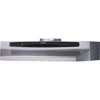
| Product Type | Range Hood |
| Brand | NuTone |
| Model | NSPM390 |
| Use | Indoor Only |
| Recommended Mounting Distance | 24 to 30 inches (61 to 76 cm) above cooking surface |
| Minimum Cabinet Interior Height | 16 inches (406.4 mm) |
| Electrical Supply | 120 V, 60 Hz |
| Lamp Rating | 2 bulbs max 40 W (base, not included) |
| Motor Speeds | 2 speeds (low and high) + off |
| Thermal Safety System | Heat Sentry™: thermostat activating fan on high speed in case of excessive heat |
| Venting Type | 6-inch (15.2 cm) round metal duct to outside or recirculation with charcoal filter (optional) |
| Grease Filter | Dishwasher safe or hand wash with detergent |
| Charcoal Filter | Replace every 6 months (sold separately) |
| Grounding | Required, Class I appliance |
| Warranty | 1 year limited (parts and labor) |
| Material | Metal |
| Controls | Mechanical switches for light and motor |
| Maintenance | Regular cleaning of filters and surface; always disconnect power before servicing |
| Replacement Parts | Available (motor, blower wheel, switches, filters, etc.) |
Frequently Asked Questions - NSPM390 NuTone
User questions about NSPM390 NuTone
0 question about this device. Answer the ones you know or ask your own.
Ask a new question about this device
Download the instructions for your Basket in PDF format for free! Find your manual NSPM390 - NuTone and take your electronic device back in hand. On this page are published all the documents necessary for the use of your device. NSPM390 by NuTone.
USER MANUAL NSPM390 NuTone
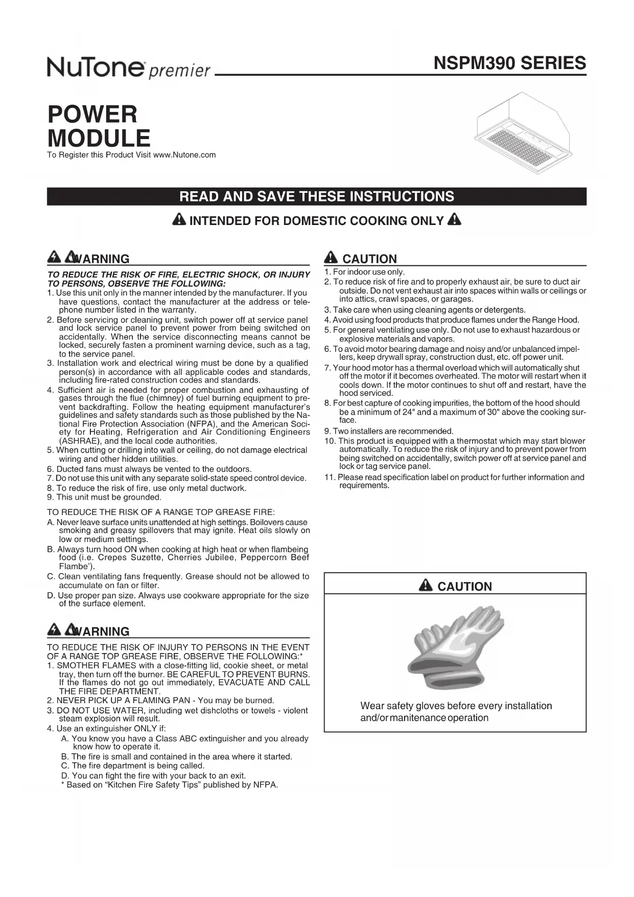
To Register this Product Visit www.Nutone.com
natural_image
Isometric line drawing of a rectangular enclosure with a grid-patterned base and a small rectangular cutout on top (no text or symbols)READ AND SAVE THESE INSTRUCTIONS
- Use this unit only in the manner intended by the manufacturer. If you have questions, contact the manufacturer at the address or telephone number listed in the warranty.
- Before servicing or cleaning unit, switch power off at service panel and lock service panel to prevent power from being switched on accidentally. When the service disconnecting means cannot be locked, securely fasten a prominent warning device, such as a tag, to the service panel.
- Installation work and electrical wiring must be done by a qualified person(s) in accordance with all applicable codes and standards, including fire-rated construction codes and standards.
- Sufficient air is needed for proper combustion and exhausting of gases through the flue (chimney) of fuel burning equipment to prevent backdrafting. Follow the heating equipment manufacturer's guidelines and safety standards such as those published by the National Fire Protection Association (NFPA), and the American Society for Heating, Refrigeration and Air Conditioning Engineers (ASHRAE), and the local code authorities.
- When cutting or drilling into wall or ceiling, do not damage electrical wiring and other hidden utilities.
- Ducted fans must always be vented to the outdoors.
- Do not use this unit with any separate solid-state speed control device.
- To reduce the risk of fire, use only metal ductwork.
- This unit must be grounded.
TO REDUCE THE RISK OF A RANGE TOP GREASE FIRE:
A. Never leave surface units unattended at high settings. Boilovers cause smoking and greasy spillovers that may ignite. Heat oils slowly on low or medium settings.
B. Always turn hood ON when cooking at high heat or when flambeing food (i.e. Crepes Suzette, Cherries Jubilee, Peppercorn Beef Flambe').
C. Clean ventilating fans frequently. Grease should not be allowed to accumulate on fan or filter.
D. Use proper pan size. Always use cookware appropriate for the size of the surface element.
WARNING
TO REDUCE THE RISK OF INJURY TO PERSONS IN THE EVENT OF A RANGE TOP GREASE FIRE, OBSERVE THE FOLLOWING:\*
- SMOTHER FLAMES with a close-fitting lid, cookie sheet, or metal tray, then turn off the burner. BE CAREFUL TO PREVENT BURNS. If the flames do not go out immediately, EVACUATE AND CALL THE FIRE DEPARTMENT.
- NEVER PICK UP A FLAMING PAN - You may be burned.
- DO NOT USE WATER, including wet dishcloths or towels - violent steam explosion will result.
- Use an extinguisher ONLY if:
A. You know you have a Class ABC extinguisher and you already know how to operate it.
B. The fire is small and contained in the area where it started.
C. The fire department is being called.
D. You can fight the fire with your back to an exit.
* Based on "Kitchen Fire Safety Tips" published by NFPA.
CAUTION
- For indoor use only.
- To reduce risk of fire and to properly exhaust air, be sure to duct air outside. Do not vent exhaust air into spaces within walls or ceilings or into attics, crawl spaces, or garages.
- Take care when using cleaning agents or detergents.
- Avoid using food products that produce flames under the Range Hood.
- For general ventilating use only. Do not use to exhaust hazardous or explosive materials and vapors.
- To avoid motor bearing damage and noisy and/or unbalanced impellers, keep drywall spray, construction dust, etc. off power unit.
- Your hood motor has a thermal overload which will automatically shut off the motor if it becomes overheated. The motor will restart when it cools down. If the motor continues to shut off and restart, have the hood serviced.
- For best capture of cooking impurities, the bottom of the hood should be a minimum of 24" and a maximum of 30" above the cooking surface.
- Two installers are recommended.
- This product is equipped with a thermostat which may start blower automatically. To reduce the risk of injury and to prevent power from being switched on accidentally, switch power off at service panel and lock or tag service panel.
- Please read specification label on product for further information and requirements.
CAUTION

natural_image
Illustration of a stylized hand or glove with layered, curved surfaces (no text or symbols)Wear safety gloves before every installation and/or manitenance operation
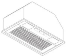
NOTE: To reduce the risk of fire, use only metal ductwork.
- Decide where the ductwork will run between the hood and the outside (Refer to Figure 1).
- A straight, short duct run will allow the hood to perform most efficiently.
- Long duct runs, elbows, and transitions will reduce the performance of the hood. Use as few of them as possible. Larger ducting may be required for best performance with longer duct runs.
- Install a roof or wall cap. Connect round metal ductwork to cap and work back towards hood location. Use duct tape to seal the joints between ductwork sections.
text_image
ROOF CAP ROUND DUCT WALL CAP POWER MODULE 6" ROUND ELBOW 24" TO 30" ABOVE COOKING SURFACE FIG. 1INSTALL THE HOOD
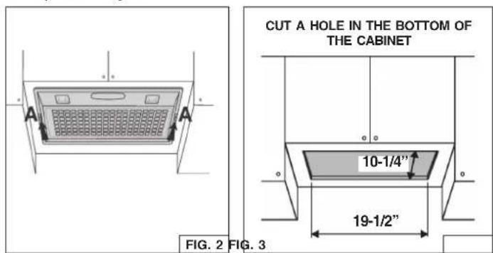
NOTE: the hood has to be installed, inside the cabinet, at minimum 1" from the rear wall cabinet and at 3" from the front wall cabinet.
The internal height of cabinet has to be minimum 16".
The hood should be mounted centered over the cook top burners.
- Remove the grid by moving the 2 slide fasteners "A" forward (Fig.2).
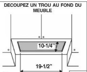
- Cut a hole in the bottom of the cabinet, using the dimensions shown (Fig. 3).
- Adjust the position of the clasping side spring by means of the proper "B" screw according to the thickness of the bored panel to which it is going to be anchored (Fig. 4).
- NOTE: For installations where the Power Pack is less than 30" above cook top, it is recommended that the Power Pack be mounted into a metal liner or non-combustible material. This will allow easier cleaning and provide protection to the cabinetry (Fig.5A).
- Insert the hood in the cabinet and lock it by means of the side spring.
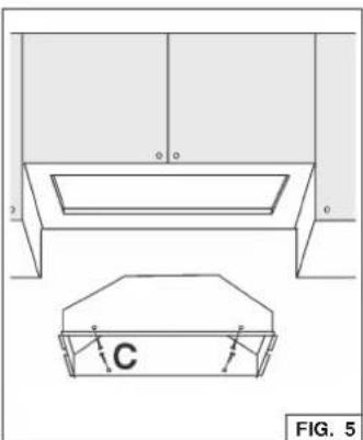
- Insert the hood in the cabinet (Fig. 5) or metal liner (Fig. 5A) and secure with the (4) "C" mounting sheet metal screws.
(Fig. 5 - wood bottom installation; recommended thickness 1/2"-3/4").
(For alternate mounting, use machine screws with washers and nuts. This alternate mounting method needs to be done prior to installation of metal liner).
-
In the Non-Ducted Recirculation Configuration, install the Non-ducted recirculation Filter before replacing the grid (see section "Non-ducted recirculation filter installation").
-
Replace the grid.
text_image
CUT A HOLE IN THE BOTTOM OF THE CABINET 10-1/4" 19-1/2" FIG. 2 FIG. 3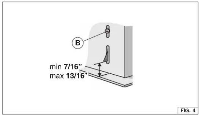
text_image
B min 7/16" max 13/16" FIG. 4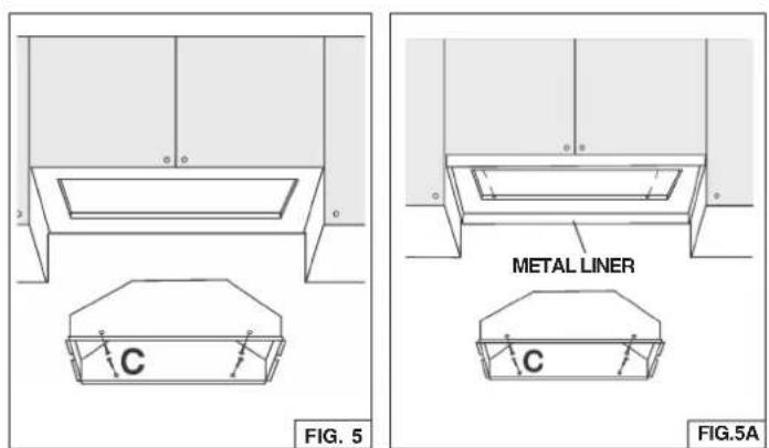
text_image
C FIG. 5 METAL LINER C FIG.5ACONNECT DUCTWORK
Ducted Configuration
- Take the damper and assemble it onto the hood's discharge opening, pressing slightly.
- Use 6" round metal duct to connect the discharge collar on the hood to the ductwork above.
- Use duct tape to make all joints secure and air tight.
Non-Ducted Recirculation Configuration
- Connect a 6" round metal duct to the discharge opening so that the air is sent outside the cabinet and sent back into the room.
- Use duct tape to make all joints secure and air tight.
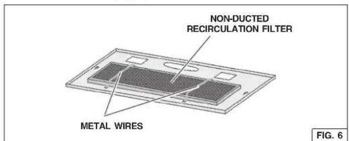
NON-DUCTED RECIRCULATION FILTER INSTALLATION
- Remove the metal wires (Fig. 9) and discard them.
- Install the Non-ducted recirculation filter over the grease filter and secure it with the metal wires supplied with the Non-ducted recirculation Filter (Fig. 6).
text_image
NON-DUCTED RECIRCULATION FILTER METAL WIRES FIG. 6Note: This range hood must be properly grounded.
The unit should be installed by a qualified electrician in accordance with all applicable national and local electrical codes. GROUNDING INSTRUCTIONS
This appliance must be grounded. In the event of an electrical short circuit, grounding reduces the risk of electric shock by providing an escape wire for the electric current. This appliance is equipped with a cord having a grounding wire with a grounding plug. The plug must be plugged into an outlet that is properly installed and grounded.
WARNING - Improper grounding can result in a risk of electric shock. Consult a qualified electrician if the grounding instructions are not completely understood, or if doubt exists as to whether the appliance is properly grounded.
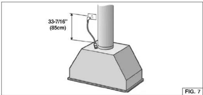
Do not use an extension cord. If the power supply cord is too short, have a qualified electrician install an outlet near the appliance. Position the electrical outlet at a maximum distance of 33-7/16" (85 cm) from where the lead exits from the hood (see illustration alongside).
Fit the plug into the outlet.
text_image
33-7/16" (85cm) FIG. 7OPERATION
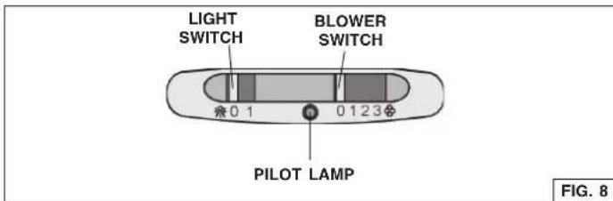
Controls
The light switch turns the lamps on and off.
The blower switch: makes it possible to select the motor operating speed. Position 0: motor off.
The pilot lamp lights up whenever the blower is on.
text_image
LIGHT SWITCH BLOWER SWITCH 0 1 0 123 PILOT LAMP FIG. 8HEAT SENTRY™
Your hood is equipped with a HEAT SENTRY™ thermostat.
This thermostat is a device that will turn on or speed up the blower if it senses excessive heat above the cooking surface.
1) If blower is OFF - it turns blower ON to HIGH speed.
2) If blower is ON at a lower speed setting - it turns blower up to HIGH speed.
When the temperature level drops to normal, the blower will return to its original setting.
WARNING
The HEAT SENTRY thermostat can start the blower even if the hood is turned OFF. When this occurs, it is impossible to turn the blower OFF with its switch. If you must stop the blower, do it from the main electrical panel.
MAINTENANCE
ALWAYS SWITCH OFF THE ELECTRICITY SUPPLY BEFORE CARRYING OUT ANY OPERATIONS ON THE APPLIANCE.
Grease Filter
The grease filter should be cleaned frequently. Use a warm detergent solution. Grease filter is dishwasher safe.
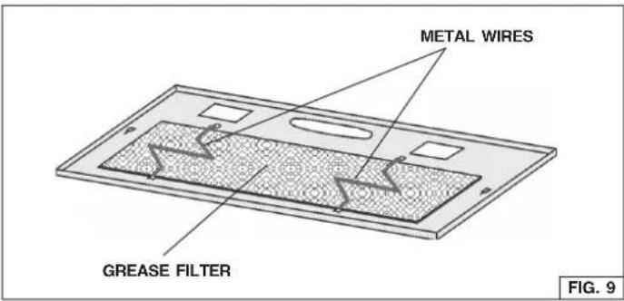
To remove the grease filter: remove the grid by moving the 2 slide fasteners "A" (Fig. 2); remove the metal wires and then the grease filter (Fig. 9).
text_image
METAL WIRES GREASE FILTER FIG. 9Non-Ducted Recirculation Filter
The Non-Ducted Recirculation filter should be changed every 6 months.
To remove the Non-Ducted Recirculation filter:
-
Remove the grid by moving the 2 side fasteners "A" (Fig. 2).
-
Remove the metal wires (Fig. 6) and replace the Non-ducted recirculation Filter.
Cleaning
Occasional care will help preserve its fine appearance.
- Clean with warm water and mild detergent only.
- Follow all cleaning by rinsing with clear water.
• Wipe dry with clean, soft cloth.
Light bulbs
This range hood requires two 40-Watt light bulbs (not included). To change bulbs:
-
Remove the grid by moving the 2 slide fasteners (A).
-
Replace with light bulbs of the same type (MAX 40W, 120V, Candelabra Base Bulb). CAUTION: BULB MAY BE HOT!
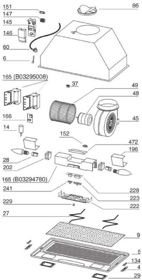
SERVICE PARTS
KEY NO. PART NO. DESCRIPTION
| 4 B03295038 Side Fastener | |
| 5 B03127682 Grid | |
| 6 B02011013 Spring | |
| 9 B08087922 Grease Filter | |
| 14 B02300233 Condenser | |
| 27 B02011155 Metal Wires | |
| 28 B02300280 Lampholder | |
| 29 B03293051 Light Fitting | |
| 37 B02300787 Heat Sentry | |
| 45 BW0000043 Blower | |
| 48 B02310203 Motor | |
| 49 B03295076 Blower Wheel | |
| 60 B02300249 Feeder Cable | |
| 86 B08088378 Damper | |
| 134 B03295039 Grid Stop | |
| 145 B032920170 Wiring Box | |
| 146 B032920180 Wiring Box Cover | |
| 147 BR2300132 Terminal Block | |
| 151 B032920200 Wire Clamp | |
| 152 B03292200 Wire Clamp | |
| 165 B03294780 Controls Box | |
| 165 B03295008 Box Condenser | |
| 166 B08086668 Heat Sentry Board | |
| 196 BE3348672 Reflector | |
| 202 B03294779 Runner Wires | |
| 222 B03295040 Control Box Cover | |
| 223 B03295042 Blower Switch | |
| 228 B08086285 Controls Board | |
| 229 B03201014 Pilot Lamp | |
| 241 B03295041 Light Switch | |
| 472 BE3344843 Controls Bracket | |
| 998 B080810782 Hardware Package | |
| CAS B06002125 Blower Assembly(Included Key No. 45, 48, 49) | |
| AQI | B06108860 Switch box Assembly(Included Key No. 165, 228, 28, 222, 152, 241, 223, 202, 229) |
| - | - "40 Watt Max.Candelabra Bulbs not included" |
| - | B08999040 Non-Ducted Filter Kit(purchased separately) |
text_image
Exploded view diagram of a device with numbered parts and Chinese labels, including a top-down view of the front panel.WARRANTY
ONE YEAR LIMITED WARRANTY FOR NUTONE PRODUCTS
Broan-NuTone LLC (Broan-NuTone) warrants to the original consumer purchaser of NuTone products that such products will be free from defects in materials or workmanship for a period of one year from the date of original purchase. THERE ARE NO OTHER WARRANTIES, EXPRESS OR IMPLIED, INCLUDING, BUT NOT LIMITED TO, IMPLIED WARRANTIES OR MERCHANTABILITY OR FITNESS FOR A PARTICULAR PURPOSE.
During this one-year period, Broan-NuTone will, at its option, repair or replace, without charge, any product or part which is found to be defective under normal use and service.
THIS WARRANTY DOES NOT EXTEND TO FLUORESCENT LAMP STARTERS, TUBES, HALOGEN AND INCANDESCENT BULBS, FUSE, FILTERS, DUCTS, ROOF CAPS, WALL CAPS AND OTHER ACCESSORIES FOR DUCTING. This warranty does not cover (a) normal maintenance and service or (b) any products or parts which have been subject to misuse, negligence, accident, improper maintenance or repair (other than by Broan-NuTone), faulty installation or installation contrary to recommended installation instructions.
The duration of any implied warranty is limited to the one-year period as specified for the express warranty. Some states do not allow limitation on how long an implied warranty lasts, so the above limitation may not apply to you.
BROAN-NUTONE'S OBLIGATION TO REPAIR OR REPLACE, AT BROAN-NUTONE'S OPTION, SHALL BE THE PURCHASER'S SOLE AND EXCLUSIVE REMEDY UNDER THIS WARRANTY. BROAN-NUTONE SHALL NOT BE LIABLE FOR INCIDENTAL, CONSEQUENTIAL OR SPECIAL DAMAGES ARISING OUT OF OR IN CONNECTION WITH PRODUCT USE OR PERFORMANCE. Some states do not allow the exclusion or limitation of incidental or consequential damages, so the above limitation or exclusion may not apply to you.
This warranty gives you specific legal rights, and you may also have other rights, which vary from state to state. This warranty supersedes all prior warranties.
To qualify for warranty service, you must (a) notify Broan-NuTone at the address stated below or telephone number stated below, (b) give the model number and part identification and (c) describe the nature of any defect in the product or part. At the time of requesting warranty service, you must present evidence of the original purchase date.
In USA - NuTone®, 926 W. State Street, Hartford, WI 53027 (800-558-1711)
In Canada - NuTone®, 550 Lemire Blvd., Drummondville, QC J2C 7W9 (866-737-7770)
www.nutone.com
MODULE DE PUISSANCE
natural_image
Isometric line drawing of a technical component or enclosure with grid-like structure and no visible text or symbolsLISEZ ET CONSERVEZ CES INSTRUCTIONS
⚠️ SEULEMENT POUR UTILISATION DOMESTIQUE ⚠️
VERTISSEMENTS
POUR REDUIRE LES RISQUES D'INCENDIE, DE DECHARGES ELECTRIQUES OU DE DOMMAGES AUX PERSONNES, OBSERVEZ LES INSTRUCTIONS SUIVANTES:
natural_image
Illustration of a hand with fingers spread, no text or symbols presentnatural_image
Diagram of a ventilation grille with labeled points A and v, showing no text or symbols beyond labelsFIG. 2 FIG. 3
text_image
DECOUPEZ UN TROU AU FOND DU MEUBLE 10-1/4" 19-1/2"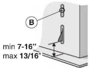
text_image
B min 7-16" max 13/16"FIG. 4
natural_image
Technical line drawing of a mechanical component with labeled parts (no text or symbols beyond labels)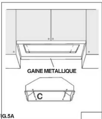
text_image
GAINÉ METALLIQUE C G.5ACONNEXION DU SYSTEME D'EVACUATION
text_image
33-7/16" (85cm) FIG. 7FONCTIONNEMENT
Commandes
28, 222, 152, 241, 223, 202,
229)
"Culot 40 Watt Max."
Ampoules non comprises"
In USA - NuTone®, 926 W. State Street, Hartford, WI 53027 (800-558-1711)
In Canada - NuTone®, 550 Lemire Blvd., Drummondville, QC J2C 7W9 (866-737-7770)
www.nutone.com