GDT2565XC - Basket GRUNDIG - Free user manual and instructions
Find the device manual for free GDT2565XC GRUNDIG in PDF.

User questions about GDT2565XC GRUNDIG
0 question about this device. Answer the ones you know or ask your own.
Ask a new question about this device
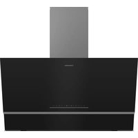
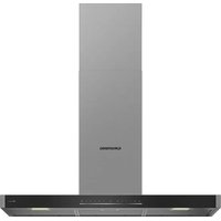
Download the instructions for your Basket in PDF format for free! Find your manual GDT2565XC - GRUNDIG and take your electronic device back in hand. On this page are published all the documents necessary for the use of your device. GDT2565XC by GRUNDIG.
USER MANUAL GDT2565XC GRUNDIG
natural_image
Simple line icon of a chimney emitting steam (no text or symbols)GDT 2565 XC
EN - DE - FR - IT
CONTENTS
| ENGLISH | 3-15 |
| DEUTSCH | 16-30 |
| FRANÇAIS | 31-43 |
| ITALIANO | 44-56 |
Please read this user manual first!
Dear Valued Customer,
Thank you for preferring this Grundig appliance. We hope that you get the best results from your appliance which has been manufactured with high quality and state-of-the-art technology. For this reason, please read this entire user manual and all other accompanying documents carefully before using the appliance and keep it as a reference for future use. If you handover the appliance to someone else, give the user manual as well. Follow the instructions by paying attention to all the information and warnings in the user manual.
Remember that this user manual may also apply to other models. Differences between models are explicitly described in the manual.
Meanings of the Symbols
Following symbols are used in various sections of this user manual:

Important information and useful hints about usage.

WARNING: Warnings against dangerous situations concerning the security of life and property.
WARNING: Warning for danger of fire.
WARNING: Warning for electric shock.
1 Important safety and environmental instructions
1.1 General safety
Important Safety Instructions Read Carefully And Keep For Future Reference This section contains safety instructions that will help protect from risk of fire, electric shock, exposure to leak microwave energy, personal injury or property damage. Failure to follow these instructions shall void any warranty.
- Grundig products comply with the applicable safety standards; therefore, in case of any damage on the appliance or power cable, it should be repaired or replaced by the dealer, service center or a specialist and authorized service alike to avoid any danger. Faulty or unqualified repair work may be dangerous and cause risk to the user.
• This appliance is intended to be used in household and similar applications such as:
-Staff kitchen areas in shops, offices and other working environments;
-Farm houses
-By clients in hotels, and other residential type environments;
-Bed and Breakfast type environments.
- Operate the appliance for its intended purpose only as described in this manual.
- The manufacturer cannot be held liable for damages resulting from improper installation or misuse of the product.
• This appliance can be used by children aged from 8 years and above and persons with reduced physical, sensory or mental capabilities or lack of experience and knowledge if they have been given supervision or instruction concerning use of the appliance in a safe way and understand the hazards
1 Important safety and environmental instructions
involved.
• Children shall not be allowed play with the appliance. Cleaning and user maintenance shall not be made by children without supervision.
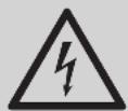
• The minimum distance between the supporting surface for the cooking vessels on the hob and the lowest part of your product must be at least 65 cm.
- If the instructions for installation for the gas hob specify a greater distance, this has to be taken into account.
- Make sure that your mains power supply complies with the information supplied on the rating plate of the appliance.
- Never use the appliance if the power cable or the appliance itself is damaged.
- Prevent damage to the power cable by not squeezing, bending, or rubbing it on sharp edges. Keep the
power cable away from hot surfaces and naked flame.
- Use the appliance with a grounded outlet only.
WARNING: Do not connect the appliance to the mains until the installation is fully complete.
- Place the appliance in a way so that the plug is always accessible.
- Do not touch the lamps if they have operated for a long time. They can burn your hands since they will be hot.
- Follow the regulations set out by competent authorities on discharge of the exhaust air (this warning is not applicable for use without flue).
- Operate your appliance after putting a pot, pan etc. on the hob. Otherwise, high heat may cause deformation in some parts of your product.
- Turn off the hob before
1 Important safety and environmental instructions
taking the pot, pan etc. from it.
- Do not leave hot oil on the hob. Pans with hot oil may cause self combustion.
- Pay attention to your curtains and covers since oil may catch fire while cooking food such as fries.
- Grease filter must be cleaned at least monthly. Carbon filter must be replaced at least every 3 months.
- Product shall be cleaned accordance with user manual. If cleaning was not carried out in accordance with user manual, there may be fire risk.
- Do not use non-fire-resistant filtering materials instead of the current filter.
- Only use the original parts or parts recommended by the manufacturer.
- Do not operate the product without the filter and do not remove the filters while the product is running.
- In the event of be started any flame, de-energize your product and cooking appliances.
• In the event of be started any flame, cover the flame and never use water to extinguish.
- Unplug the appliance before each cleaning and when the appliance is not in use.
- The negative pressure in the environment should not exceed 4 Pa (4x10 bar) while the hood for electric hob and appliances running on another type of energy but electricity operate simultaneously.
- In the environment where the appliance is being used, the exhaust of devices running on fuel oil or gas, such as room heater must be absolutely isolated or device must be hermetical type.
- When connecting the flue, use pipes with a diameter
1 Important safety and environmental instructions
of 120 or 150 mm. Pipe connection must be as short as possible and have as few elbows as possible.
- Danger of choking! Keep all the packaging materials away from children.
CAUTION: Accessible parts may become hot when used with cooking appliances.
• The product outlet must not be connected to air channels that include other smoke.
• The ventilation in the room may be insufficient when the hood for electric hob is used simultaneously with the devices operating on gas or other fuels (this may not apply to appliances that only discharge the air back into the room).
- Objects placed on the product may fall. Do not place any objects on the product.
- Do not flambe under the your product.
WARNING: Before installing the Hood, remove the protective films.
- Never leave high naked flames under the hood when it is in operation
- Deep fat fryers must be continuously monitored during use: overheated oil can burst into flames.
1.2 Compliance with the WEEE Directive and Disposing of the Waste Product:
This product complies with EU WEEE Directive (2012/19/EU). This product bears a classification symbol for waste electrical and electronic equipment (WEEE).
This symbol indicates that this product shall not be disposed with other household wastes at the end of its service life. Used device must be returned to offical collection point for recycling of electrical and electronic devices. To find these collection systems please contact to your local authorities or retailer where the product was purchased. Each household performs important role in recovering and recycling of old appliance. Appropriate disposal of used appliance helps prevent potential negative consequences for the environment and human health.
1 Important safety and environmental instructions
1.3 Compliance with RoHS Directive
The product you have purchased complies with EU RoHS Directive (2011/65/EU). It does not contain harmful and prohibited materials specified in the Directive.
1.4 Package Information
Packaging materials of the product are manufactured from recyclable materials in accordance with our National
Environment Regulations. Do not dispose of the packaging materials together with the domestic or other wastes. Take them to the packaging material collection points designated by the local authorities.
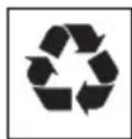
2 General appearance
2.1 Overview
- Body
- Control panel
- Grease filter
- Lighting
2.2 Technical data
| Model | GDT 2565 XC |
| Supply Voltage and Frequency | 220 - 240V~ 50Hz |
| Lamp power | 5 W |
| Motor power | 200 W |
| Air flow - 3. Level | 515 m^3/h |
| Motor insulation class | CLASS F |
| Insulation Class | CLASS I |
3 Operation of the appliance
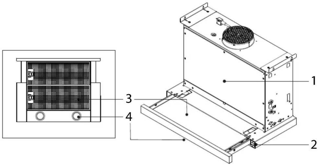
3.1 Controlling the appliance
| 1: Button ON/OFF light | Press this button to switch the lamp on and off. |
| 2: Button ON/OFF Timer | Delayed switch-off of the selected suction speed (power):Suction speed (power) 1: 20 minutesSuction speed (power) 2: 15 minutesSuction speed (power) 3: 10 minutesIntensive suction speed (power): 5 minutes |
| 3: Button OFF | Decrease of suction speed (power) |
| 4: Button ON | Increase of suction speed (power) |
| E: Display | a. Suction speed (power): LEDs L1 - L2 - L3 - L4 (flashing) light up according to the selected suction speed (power).Note: The L4 LED - intensive suction speed (power) works for about 5 minutes, then the hood sets the intermediate speed.b.Timer: The LED of the selected speed flashes to indicate that the timer is active.c. Grease filter saturation: The L3 and L4 LEDs flash alternately at short intervals of time.d. Activated charcoal filter saturation: The L3 and L4 LEDs flash simultaneously at short intervals of time.Reset of the filter saturation indicator: Perform filter maintenance, then press button 2 until the LEDs turn off.Note: The activated charcoal filter saturation is normally disabled and is enabled only if the hood is used in the filtering version (with charcoal filter installed).In order to activate it, proceed as follows:- Switch off the hood- Keep pressed simultaneously buttons 3 and 4, until the LEDs L1 and L2 flash briefly.Repeat the operation to disable; only LED L1 flashes briefly. |
3.2 Operation of the hood
- Your appliance contains a motor that has various speeds.
- For better performance, we recommend using low speeds under normal conditions and high speeds in cases of strong odours and intense vapour.
3 Operation of the appliance
- You can start your appliance by pressing on the desired speed setting button. (3, 4)
- You can illuminate the cooking area by pressing the lamp (1).
3.3 Energy efficient usage
- When using your appliance, adjust the speed settings according to vapour and odour intensity, in order to save energy.
- Use low speeds (1-2) under normal conditions, and high speed (3) and boost mode for intense odour and vapour.
- The hood is equipped with lamps in order to illuminate the cooking area.
- Using them for environmental lighting shall cause unnecessary energy expenditure and insufficient lighting.
- For your device to consume less energy, run it at a low speed level.
- Your device will reduce energy consumption as it will run more efficiently when you provide sufficient air intake to it.
- Set your device to the intense suction power level before the formation of steam, in cases where you know that the dense steam will occur. So, you reduce energy consumption by using your device for a shorter time as it will have a sufficient air intake.
- Keep the lids of the cookware closed to reduce the steam evolving.
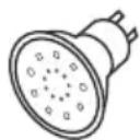
3.4 Replacement of lamp

You may procure lamps from Authorised Service Agents.

- Before replacing the light bulbs, disconnect the power supply of the hood.
- Do not touch the light bulbs when they are hot.
- Be careful not to touch the replaced light bulb directly with hands.
MAX 3 W
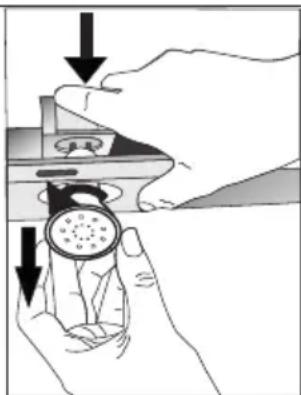
natural_image
Illustration of hands holding a device with a circular component, showing mechanical components and directional arrows (no text or symbols)Make the electrical connections of the appliance. Your appliance uses 3W spot LED lamp. For replacing the lamps, push downwards on the holder from its behind, turn it counter-clockwise, and take it out downwards. Apply the above operation in reverse to install new lamps.
| Bulb | |
| Bulb power | 2,5 W |
| Holder/Socket | ZIK7 |
| Bulb voltage | 3 V |
| Size | D56x19,6 mm |
| ILCOS code | GB/T 21656-2016 |
| Luminous flux | 268 lm |
| Correlated colour temperature | 3000 K |
This product contains a light source of energy efficiency class "F".
3 Operation of the appliance
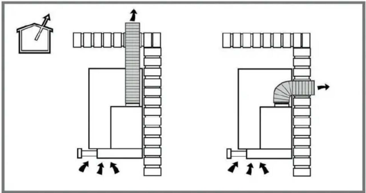
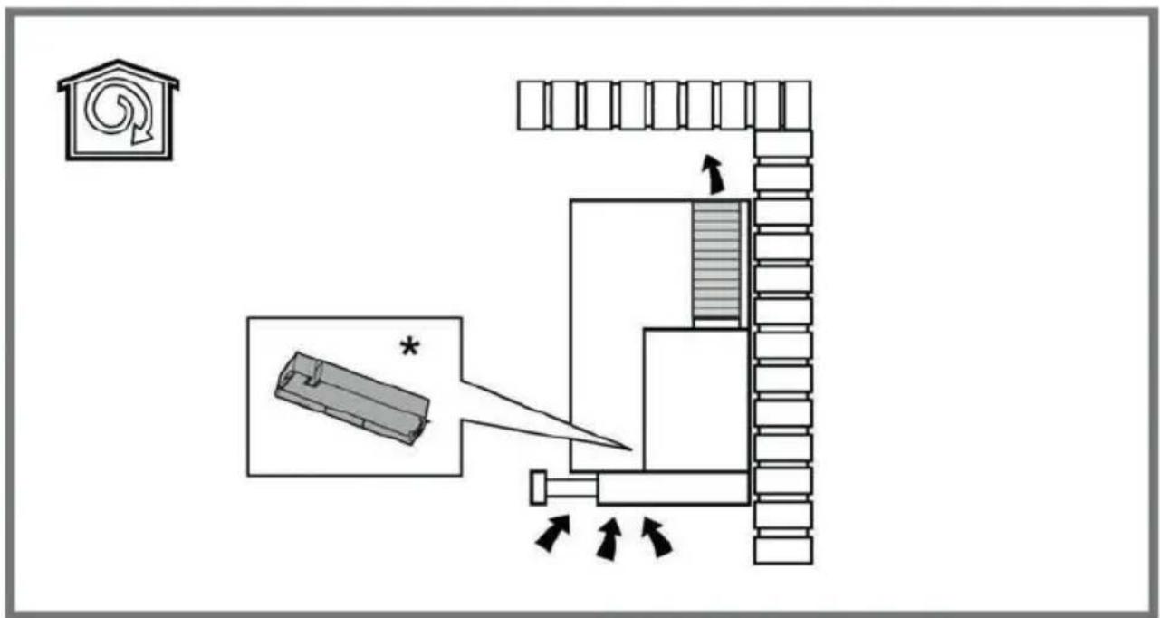
3.5 Operation with chimney connection
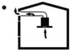
Vapour is extracted through the flue duct, which is fastened to the connection head on the hood.
(around 10°) so that the air can exit the room easily.
- The diameter of the flue duct must be the same as the connection ring. In horizontal settings, the pipe has to have a slight upward slope
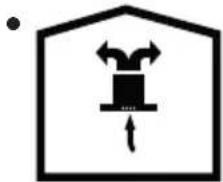
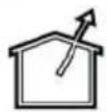
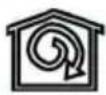
3.6 Operation without chimney connection
natural_image
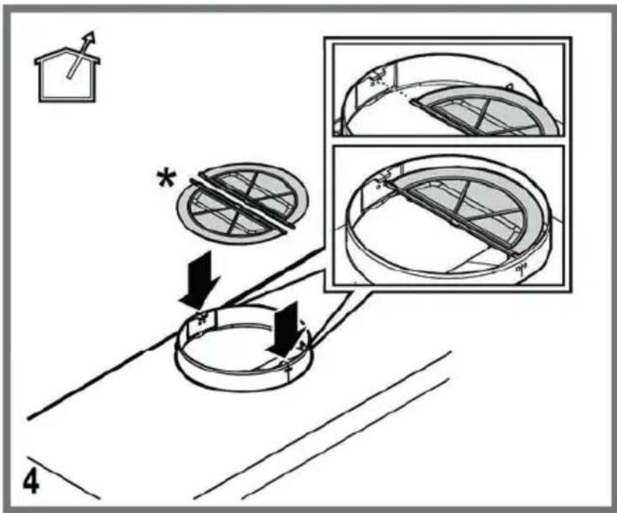
Simple line drawing of a house-shaped frame with an upward arrow inside and a central box (no text or symbols)Air is filtered through the carbon filter and recirculated in the room. Carbon filter is used when it is impossible to use a flue in the house.
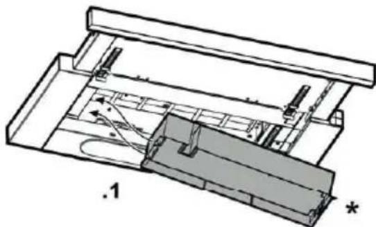
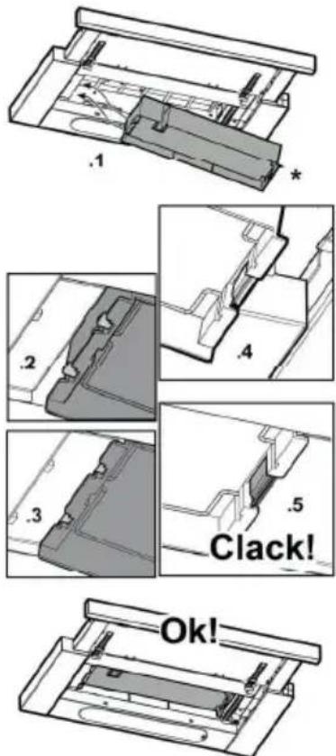
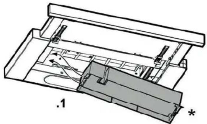
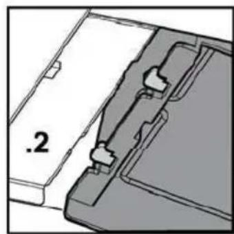
- In flueless use, remove the flaps inside the flue adapter.
- Remove the aluminum grease filter. To install the carbon filter, fit the filter to the tabs by centring it on the plastic piece on both sides of the
fan body. tighten it by turning right or left.
- Replace aluminum grease filter.
4 Clearing and maintenance
The device should be cleaned and maintained regularly. Failure to keep the device clean will adversely affect the service life of the device. For cleaning and maintenance, follow the instructions stated in the manual.

Before cleaning and maintenance, unplug the product or turn off the switch.
Non-compliance with the provisions associated with the cleaning of the device and replacement of the filters may result in a risk of fire. Therefore, it is recommended to follow the guidelines stated here. The manufacturer is not responsible for the engine damages or fires originating from the improper use.
Clean using only a cloth dampened with a neutral liquid detergent. Do not use abrasive products or alcohol.
4.1 Cleaning of the grease filter
Grease filter retains the oil particles in the air. Grease filters may change colour after repeated cleaning. This is normal and does not require replacement of filters.
-
External grease filter
-
Internal grease filter
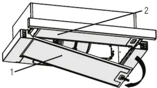
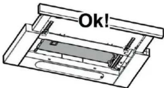
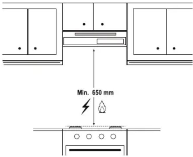
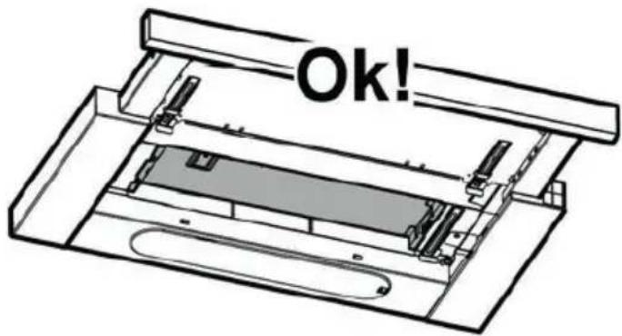
- Pull the sliding plate out by holding
4 Clearing and maintenance
the front panel. Remove the external grease filter first, and then the internal grease filter.
- Push the grease filter lock forward.
- Then lower it slightly down and pull it out. Otherwise, you can bend the filter. Wash and rinse grease filters with liquid detergent and replace grease filters to their sockets by carrying out the steps specified above in reverse order. This filter retain the oil particles in the air.

You may wash your grease filters in the dishwasher.

CAUTION: In case of normal use, clean your filter once in a month.
4.2 Replacement of carbon filters
Odour removing filters contain charcoal (Active carbon). Grease filters must be installed in the product, regardless of whether or not carbon filters are used.

CAUTION
• Carbon filter shall never be washed.
- Replace carbon filters once every 3 months.
- You can obtain the carbon filter from the authorized services.
natural_image
Technical line drawing of a mechanical assembly or lifting device with no visible text or symbols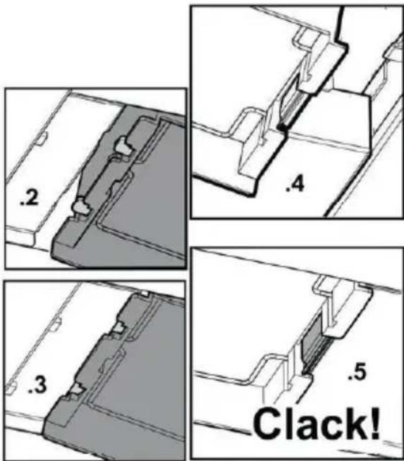
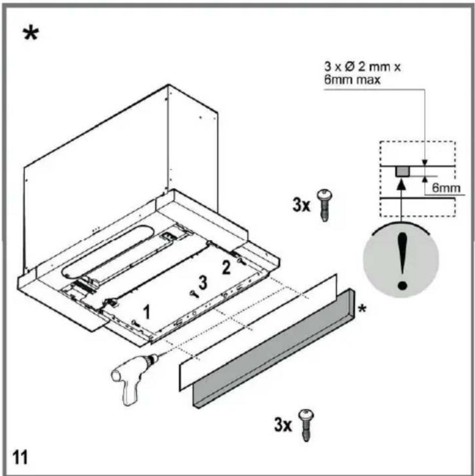
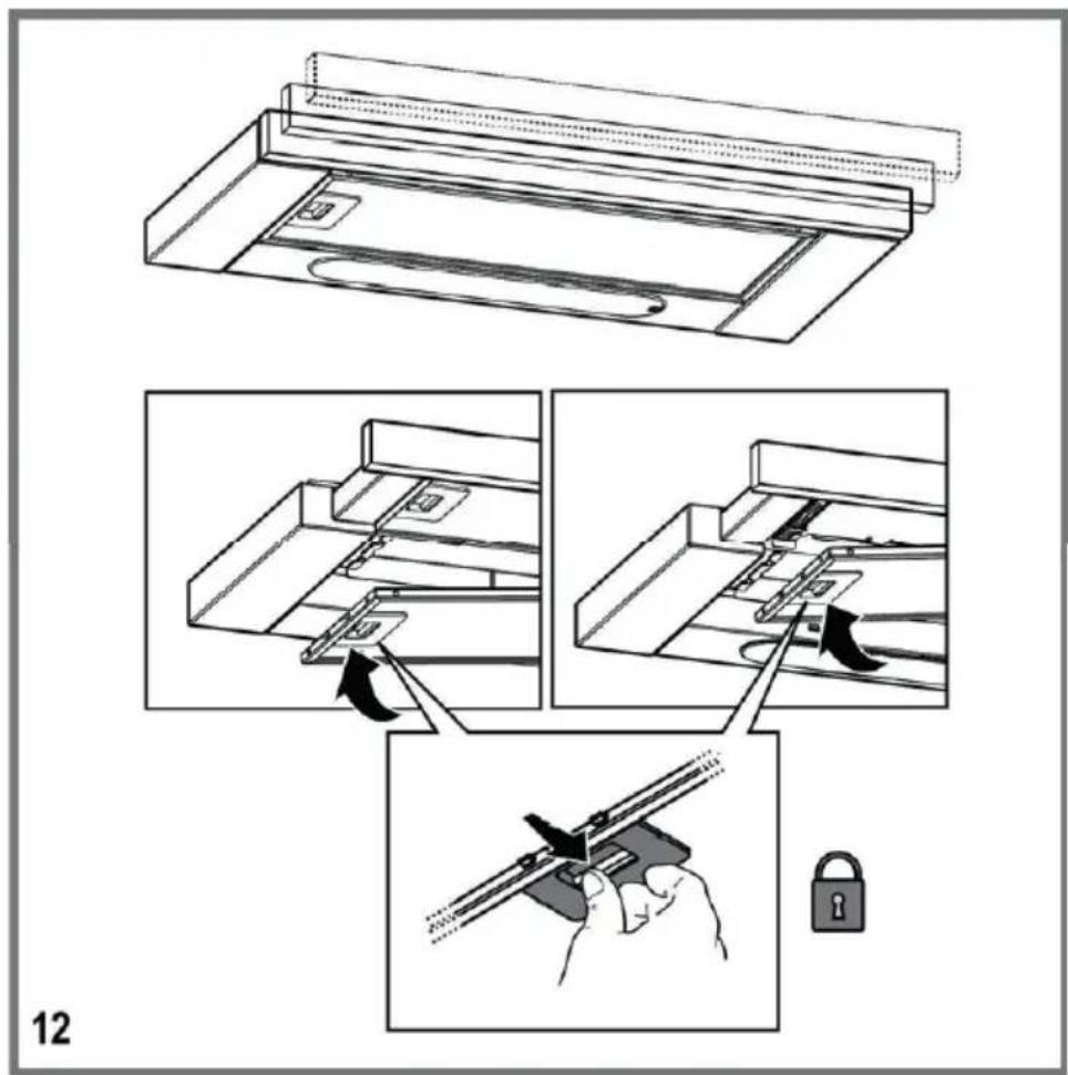
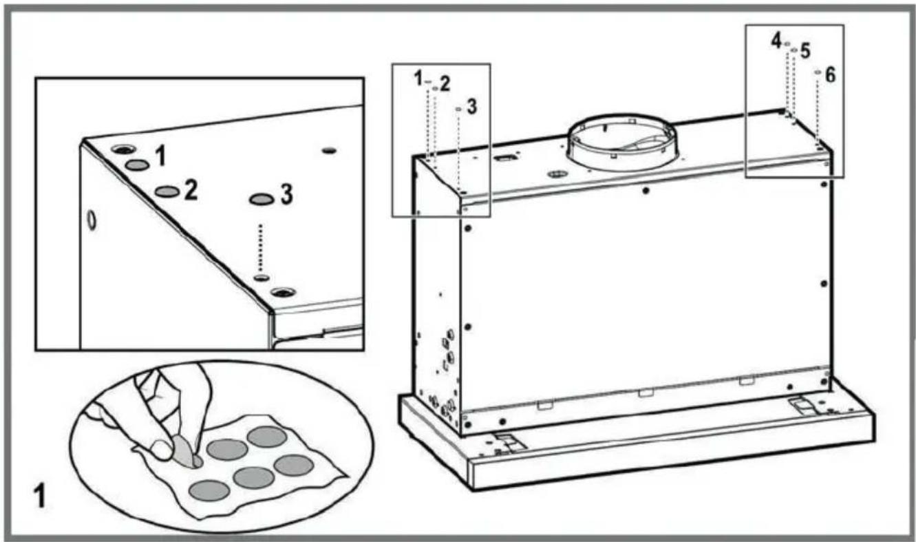
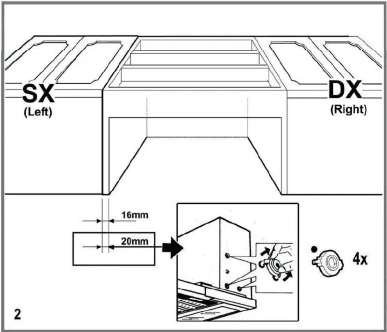
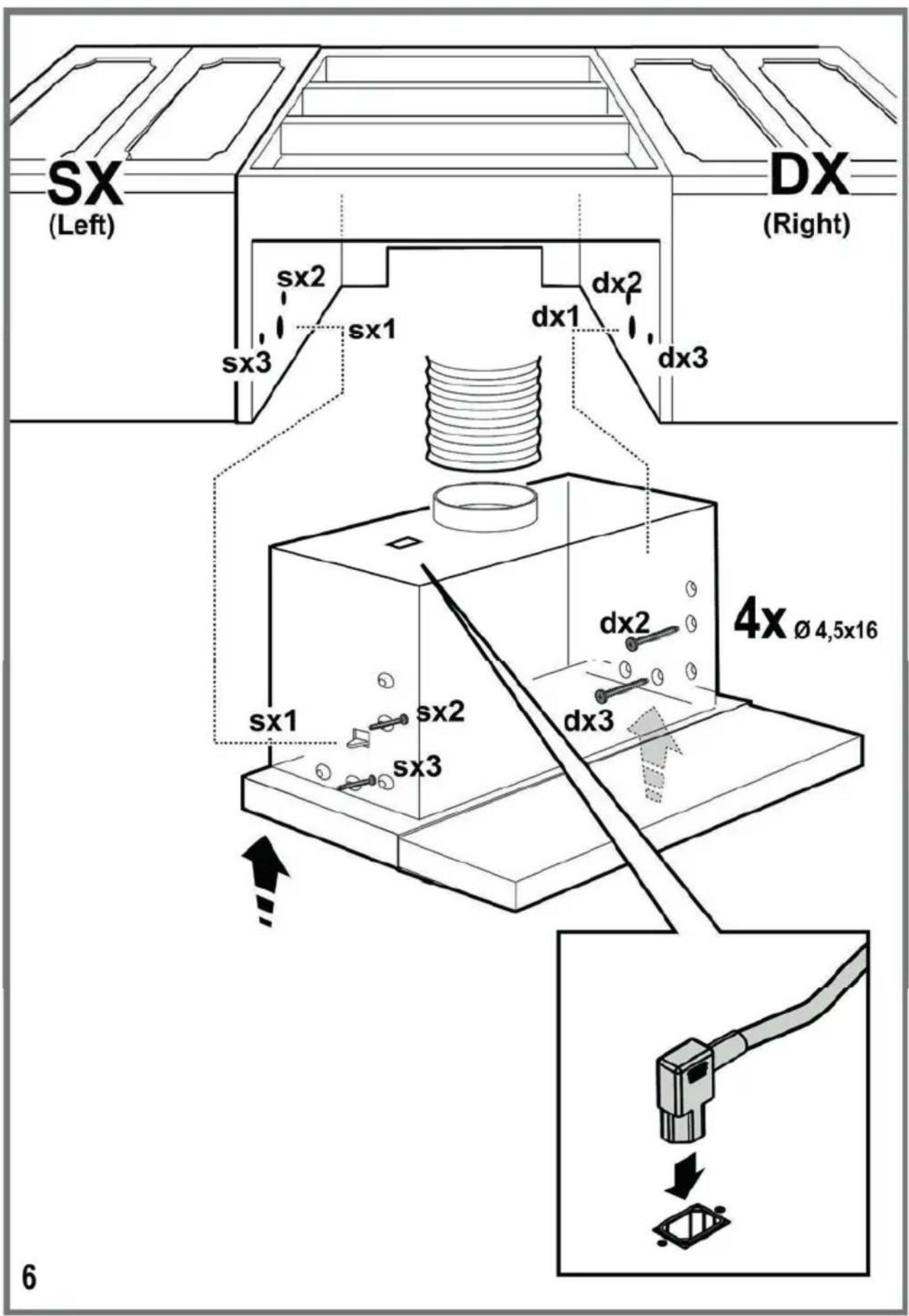
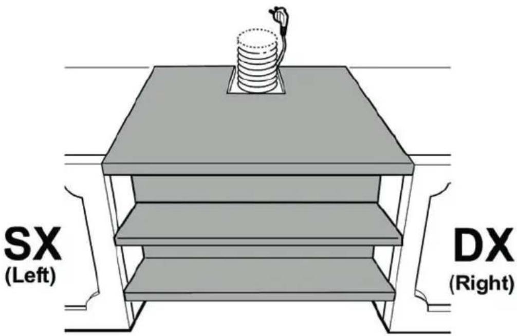
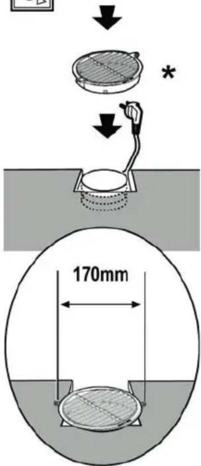
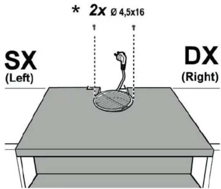
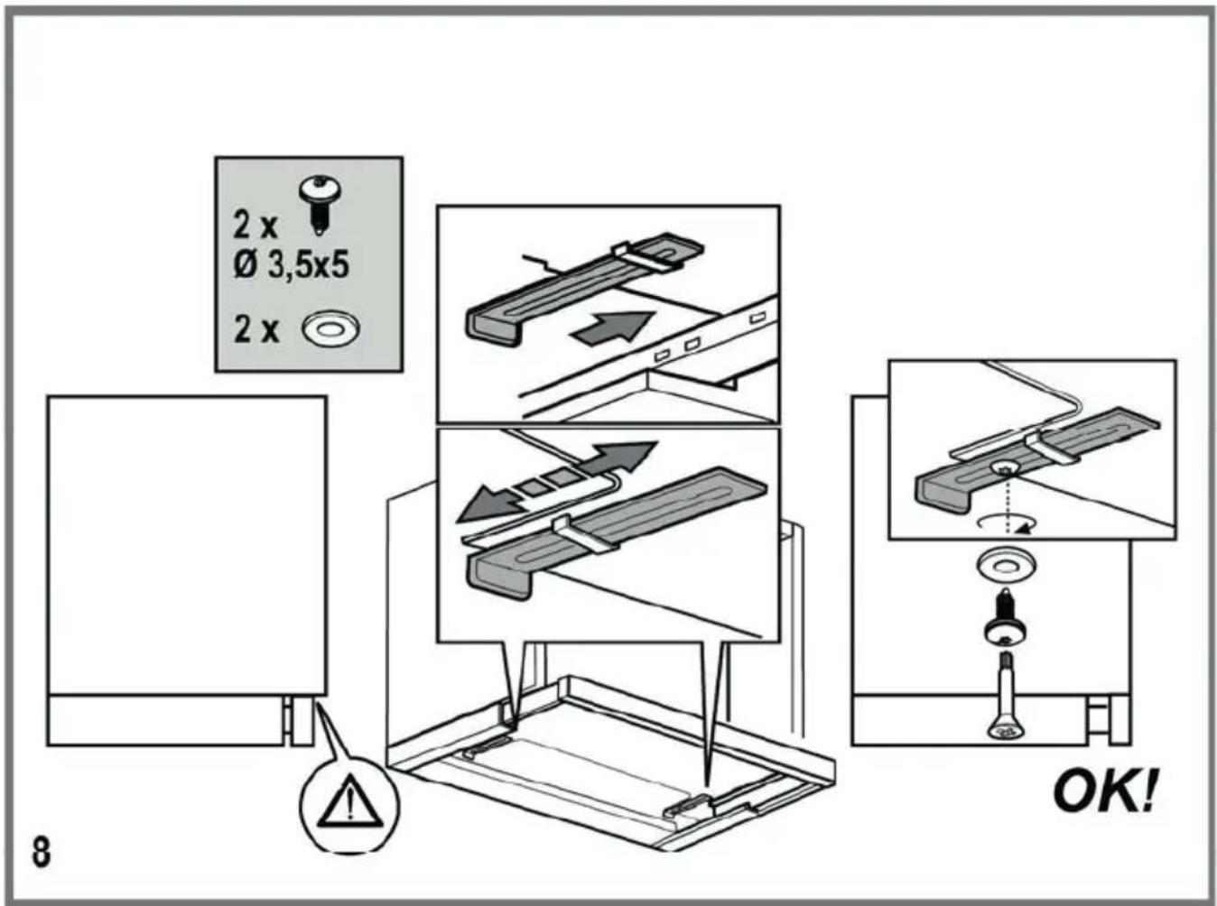
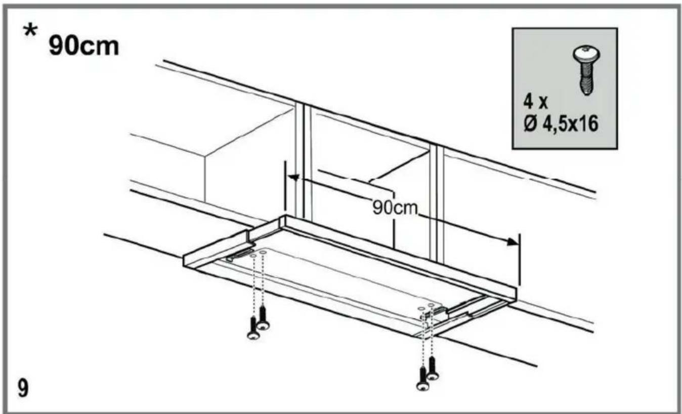
5 Installation of appliance

WARNING: Before starting the installation, read the safety information on User Manual.
WARNING: Failure to install with screws and stabilizers in accordance with these instructions may result in electric shock.

Please refer to page 57 for the installation guide.
For the installation of the hood, please contact the nearest Authorized Service.
It is the customer's responsibility to prepare the location and electrical installation of the hood.
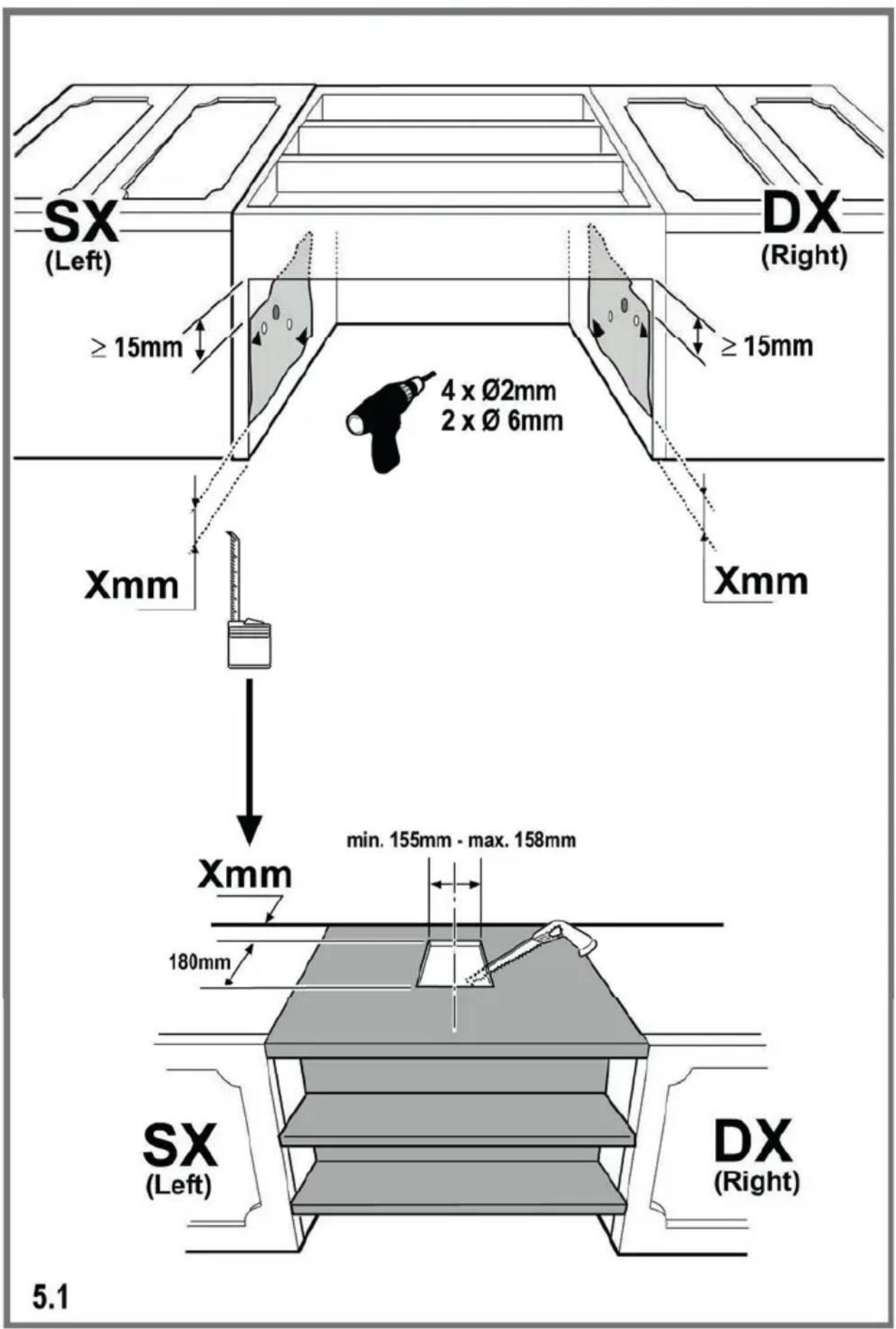
5.1 Position of the appliance
- Distance between the cooker and the cooker hood must be considered prior to assembly. This distance should be 65 cm.
- Distance must be measured from the surface of grate for gas cookers, from surface of glass for electric cookers.
5.2 Storage
- If you do not intend to use the appliance for a long time, please store it carefully.
- Please make sure that the appliance is unplugged, cooled down and totally dry.
- Store the appliance in a cool and dry place.
- Keep the appliance out of the reach of children
5.3 Handling and transportation
- During handling and transportation, carry the appliance in its original packaging. The packaging of the appliance protects it against physical damages.
- Do not place heavy loads on the appliance or the packaging. The appliance may be damaged.
- Dropping the appliance will render it non-operational or cause permanent damage.
6 Troubleshooting
| Troubleshooting Root Cause Help | ||
| Appliance is not working. Check | your fuses. Fuse may be blown, inspect and restore it. | |
| Appliance is not working. Check | the electrical connection. | Mains voltage shall be between 220 and 240 V. |
| Appliance is not working. Check | the electrical connection. | Check if other appliance in your kitchen operate. |
| Illumination light does not operate. | Check the electrical connection. | Mains voltage shall be between 220 and 240 V. |
| Illumination light does not operate. | Inspect the lamp switch. Lamp switch shall be at "on" position. | |
| Illumination light does not operate. | Inspect the lamps. The lamps of the appliance shall illuminate. | |
| Air inlet of the appliance is inadequate. | Inspect the grease filter. Under normal operating conditions, grease filter shall be cleaned at least once in a month. | |
| Air inlet of the appliance is inadequate. | Check the air discharge flue. The air discharge flue shall be at "on" position. | |
| Air inlet of the appliance is inadequate. | Inspect the carbon filter. The filters of the appliances with carbon filters shall be replaced once in every 3 months under normal conditions. |
- Externer-Fettfilter
- Interner-Fettfilter
4.2 Replacement of carbon filters
Odour removing filters contain charcoal (Active carbon). Grease filters must be installed in the product, regardless of whether or not carbon filters are used.

CAUTION
• Carbon filter shall never be washed.
- Replace carbon filters once every 3 months.
- You can obtain the carbon filter from the authorized services.
natural_image
Illustration of hands holding a mechanical component with arrows indicating force or movement (no text or symbols)natural_image
Illustration of hands using a tool to adjust a circular component with a pointer (no text or symbols)- Filtro antigrasso esterno
- Filtro antigrasso interno
natural_image
Technical line drawing of a mechanical assembly with no visible text or symbols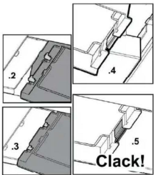
flowchart
graph TD
    A["Top Left Panel"] --> B["Top Right Panel"]
    B --> C["Bottom Left Panel"]
    C --> D["Bottom Right Panel"]
    D --> E["Bottom Left Panel"]
    E --> F["Bottom Right Panel"]
    F --> G["Bottom Left Panel"]
    G --> H["Bottom Right Panel"]
    H --> I["Bottom Left Panel"]
    I --> J["Bottom Right Panel"]
    J --> K["Bottom Left Panel"]
    K --> L["Bottom Right Panel"]
    L --> M["Bottom Left Panel"]
    M --> N["Bottom Right Panel"]
    N --> O["Bottom Left Panel"]
    O --> P["Bottom Right Panel"]
    P --> Q["Bottom Left Panel"]
    Q --> R["Bottom Right Panel"]
    R --> S["Bottom Left Panel"]
    S --> T["Bottom Right Panel"]
    T --> U["Bottom Left Panel"]
    U --> V["Bottom Right Panel"]
    V --> W["Bottom Left Panel"]
    W --> X["Bottom Right Panel"]
    X --> Y["Bottom Left Panel"]
3
natural_image
Technical line drawing of a mechanical component with no visible text or symbols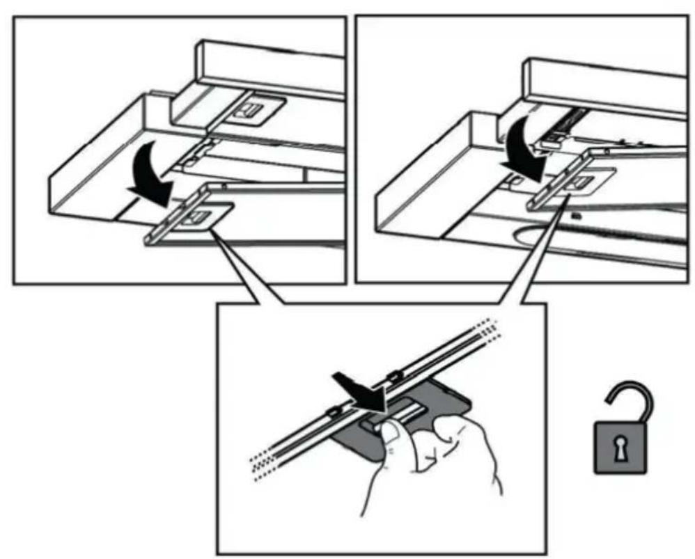

*
natural_image
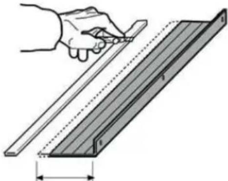
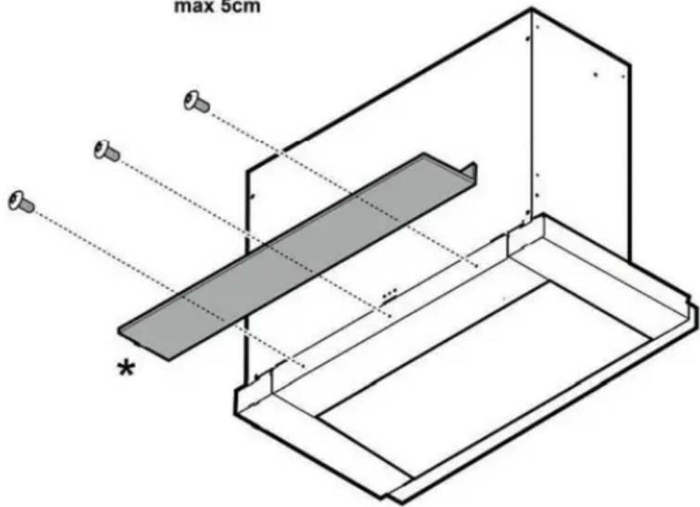
Illustration of a hand using a ruler to cut a rectangular object with a shaded section, showing dimension lines (no text or symbols)Xmm
max 5cm
5.2
7a

7b
natural_image
Technical line drawing of a mechanical assembly with internal components and directional arrows (no text or symbols)
natural_image
Diagram of a mechanical component with labeled part '2' (no text or symbols beyond the number)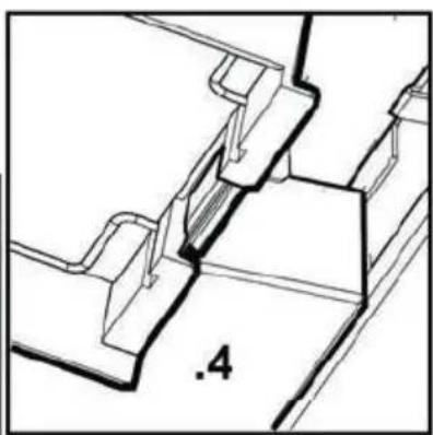
natural_image
Technical line drawing of a mechanical assembly with no visible text or symbols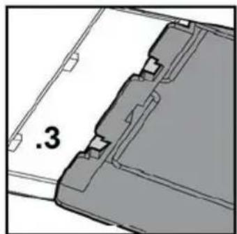
natural_image
3D mechanical part diagram showing a bracket with mounting holes and a dimension label '3' (no text or symbols beyond the number)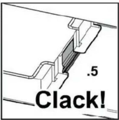
10