LWHDS 5530 - Wall mount Schwaiger - Free user manual and instructions
Find the device manual for free LWHDS 5530 Schwaiger in PDF.


| Product Type | Motorized TV Ceiling Mount |
| Brand | Schwaiger |
| Model | LWHDS 5530 |
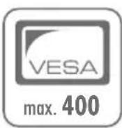
| VESA Compatibility | 100x100, 200x200, 300x300, 400x200, 400x400 mm |
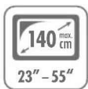
| Compatible Screen Diagonal | 23 to 55 inches (max 140 cm) |
| Maximum Load Capacity | 30 kg |
| Adjustable Tilt Angle | 0° to 75° |
| Motorization | Yes, remote control |
| Power Supply | Power adapter 100-240 V AC / 24 V DC, 1.5 A |
| Power Cord Length | 1.2 m |
| Memory Functions | Yes, up to 2 programmable positions |
| Reset | Unplug and replug, press Ⓔ for 5 seconds |
| Usage | Indoor only |
| Safety | Do not use without TV; do not open electrical compartment |
| Remote Control Batteries | 2 AAA batteries (not included) |
| Installation | On load-bearing ceiling; requires mechanical skills |
| Warranty | In accordance with legal conditions, from date of purchase |
| Manufacturer | Schwaiger GmbH, Würzburger Str. 17, 90579 Langenzenn, Germany |
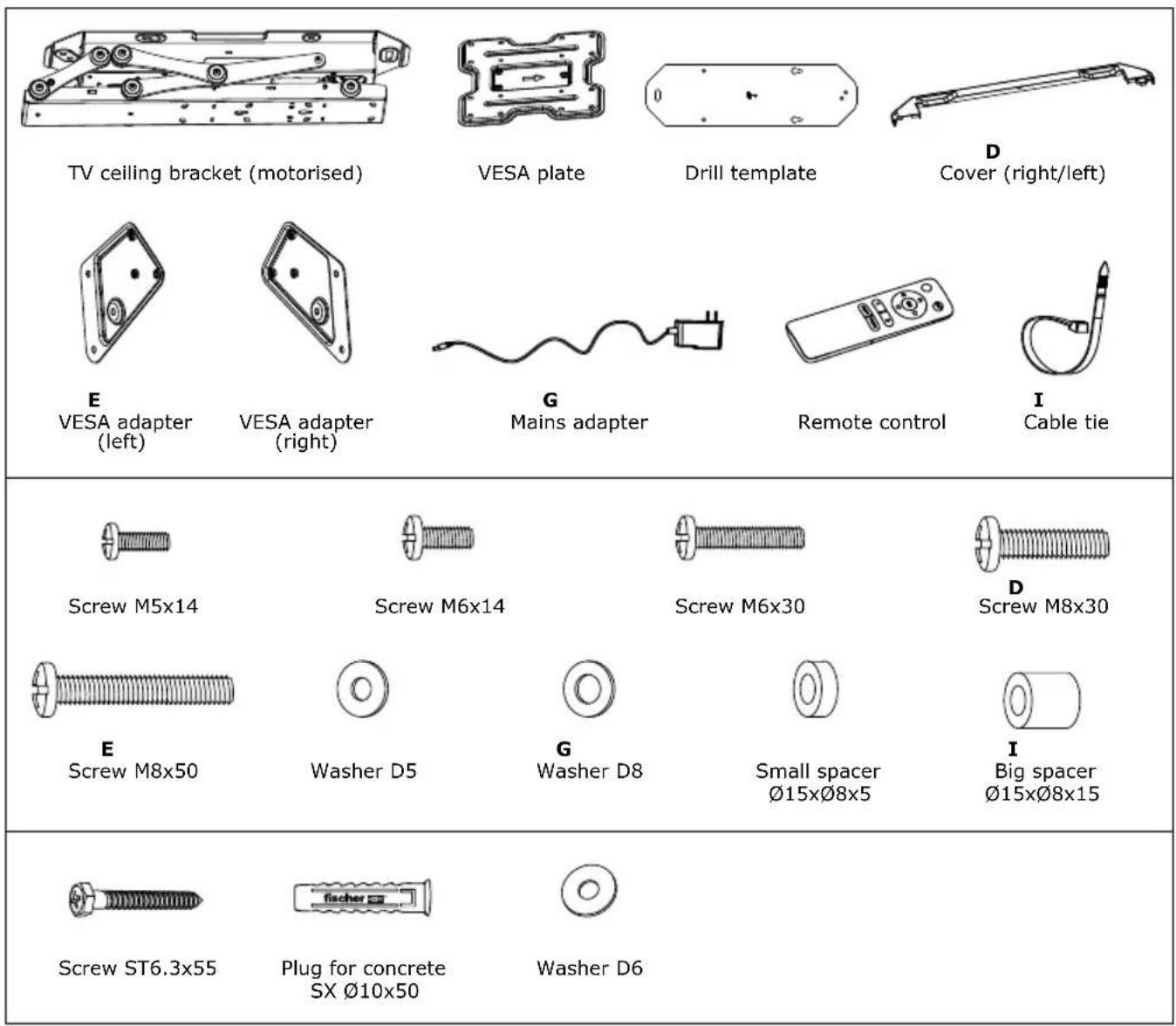
| Package Contents | VESA plate, drilling template, screws, wall plugs, cable ties, adapter, remote control |
| Cleaning | Unplug before cleaning; do not use liquids |
Frequently Asked Questions - LWHDS 5530 Schwaiger
User questions about LWHDS 5530 Schwaiger
0 question about this device. Answer the ones you know or ask your own.
Ask a new question about this device
Download the instructions for your Wall mount in PDF format for free! Find your manual LWHDS 5530 - Schwaiger and take your electronic device back in hand. On this page are published all the documents necessary for the use of your device. LWHDS 5530 by Schwaiger.
USER MANUAL LWHDS 5530 Schwaiger
D BEDIENUNGSANLEITUNG
UND SICHERHEITSHINWEISE
TV DACHSCHRÄGENHALTER
GB OPERATING AND SAFETY INSTRUCTIONS
SLOPING ROOF TV BRACKET
F MODE D'EMPLOI ET CONSIGNES DE SÉCURITÉ
SUPPORT TV POUR PLAFOND INCLINÉ
ISTRUZIONI PER L'USO
E AVVERTENZE DI SICUREZZA
SUPPORTO TV PER SOFFITTI INCLINATI
NL BEDIENINGSHANDLEIDING EN VEILIGHEIDSINSTRUCTIES TV SCHUIN DAK HOUDER
natural_image
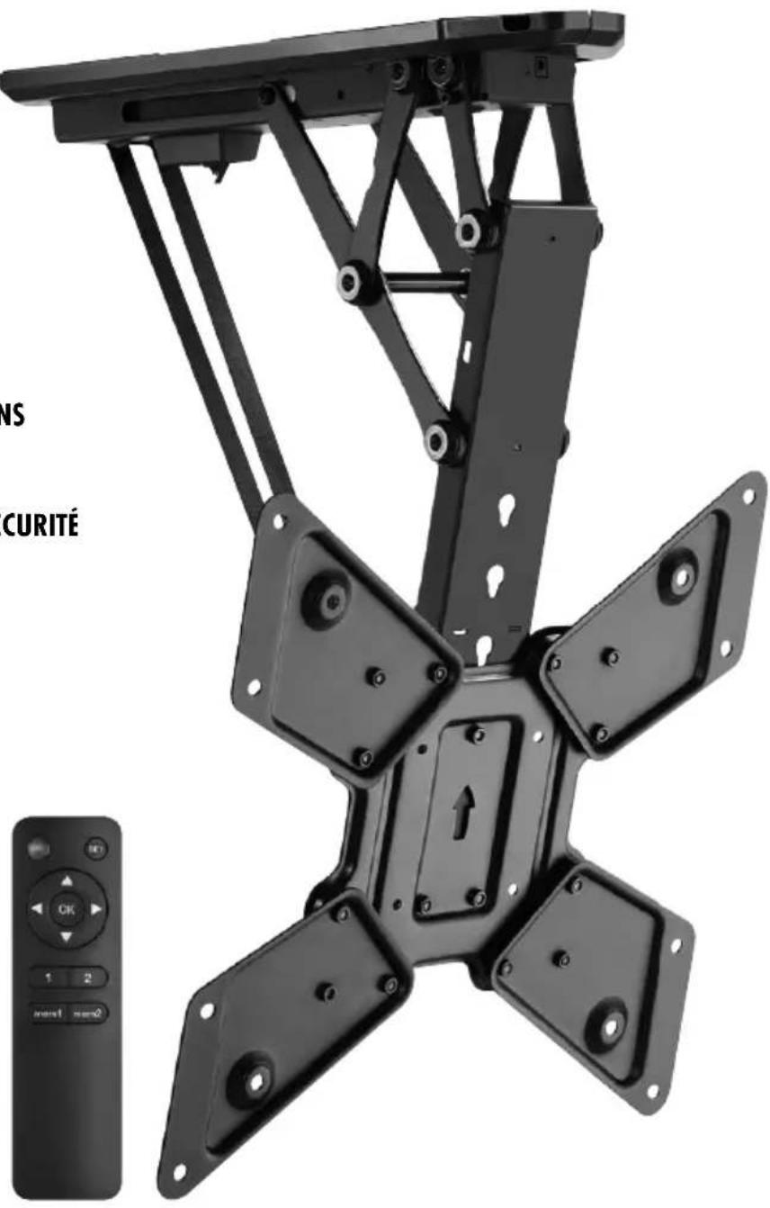
Mechanical device with four articulated arms and mounting holes, shown alongside a remote control panel (no text or symbols on the device itself)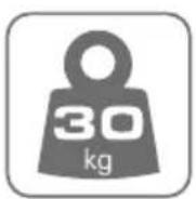
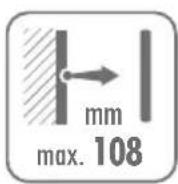
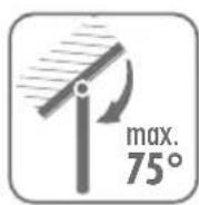
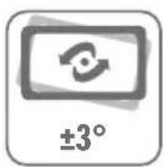

natural_image
Mechanical linkage assembly diagram with articulated arms and connecting rods (no text or symbols)ALLGEEINES
B


WARNUNG!
natural_image
Two blank rectangular panels with arrows indicating rotation, no text or symbols presentENBEDIENUNG
AT
AAB
natural_image
Technical line drawing of a mechanical assembly with a sliding guide and adjustment mechanism (no text or symbols)Congratulations and thank you for purchasing this SCHWAIGER Product.
This user manual is an integral part of this product. It contains important information on commissioning and handling. This product uses electricity. Read the instructions carefully to avoid burns, fire and electric shock, to ensure safe and correct use of the system and to preserve the life of the product in general and the built-in electronics in particular. Store this guide safely throughout the product's entire service life and pass it on to any subsequent users or owners. Check that the supplied package is complete and ensure that none of the parts are defective or damaged.
I E DED USE
The product is intended for private use only and is not suitable for commercial use.
Only use the product as described in this user manual. Any other use is considered improper and may result in property damage.
The product is used for mounting suitable TV equipment to straight or sloping ceilings. Its adjustment is motorised and can be controlled via the remote control provided. Only the mains adapter supplied may be used as a power supply for the motorised adjustment. The mains adapter is approved only for connection to an AC voltage of 100-240 V/60/50 Hz. The mounted TV screen must not exceed the specified maximum values for dimensions and weight.
Use is only allowed in closed rooms, not outdoors. Contact with moisture, e.g. in a bathroom, must be absolutely avoided.
GE ES
G
i IMPORTANT!
R
Improper handling of the product may result in damage to the product..
- Do not leave the cables and connectors lying around loose in order to prevent a tripping hazard.
- Any attempt to make changes to the product is prohibited.
- Do not start the installation until you have read and understood all instructions and warnings in this installation sheet. If you have any questions about the instructions or warnings, please contact your local dealer.
- This bracket should ONLY be installed and used as described in this manual. Improper installation of this product may result in damage or serious injury.
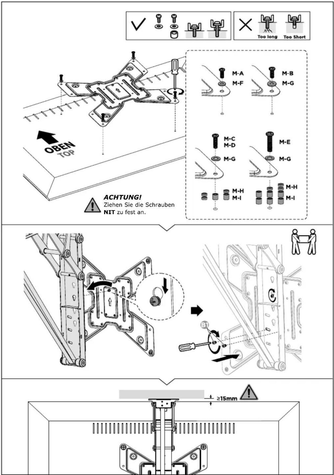
- This product should only be installed by a person with good mechanical skills who has basic experience in the field of construction and fully understands this manual.
- Make sure that the substrate can safely support the total weight of the unit and all attached parts and components.
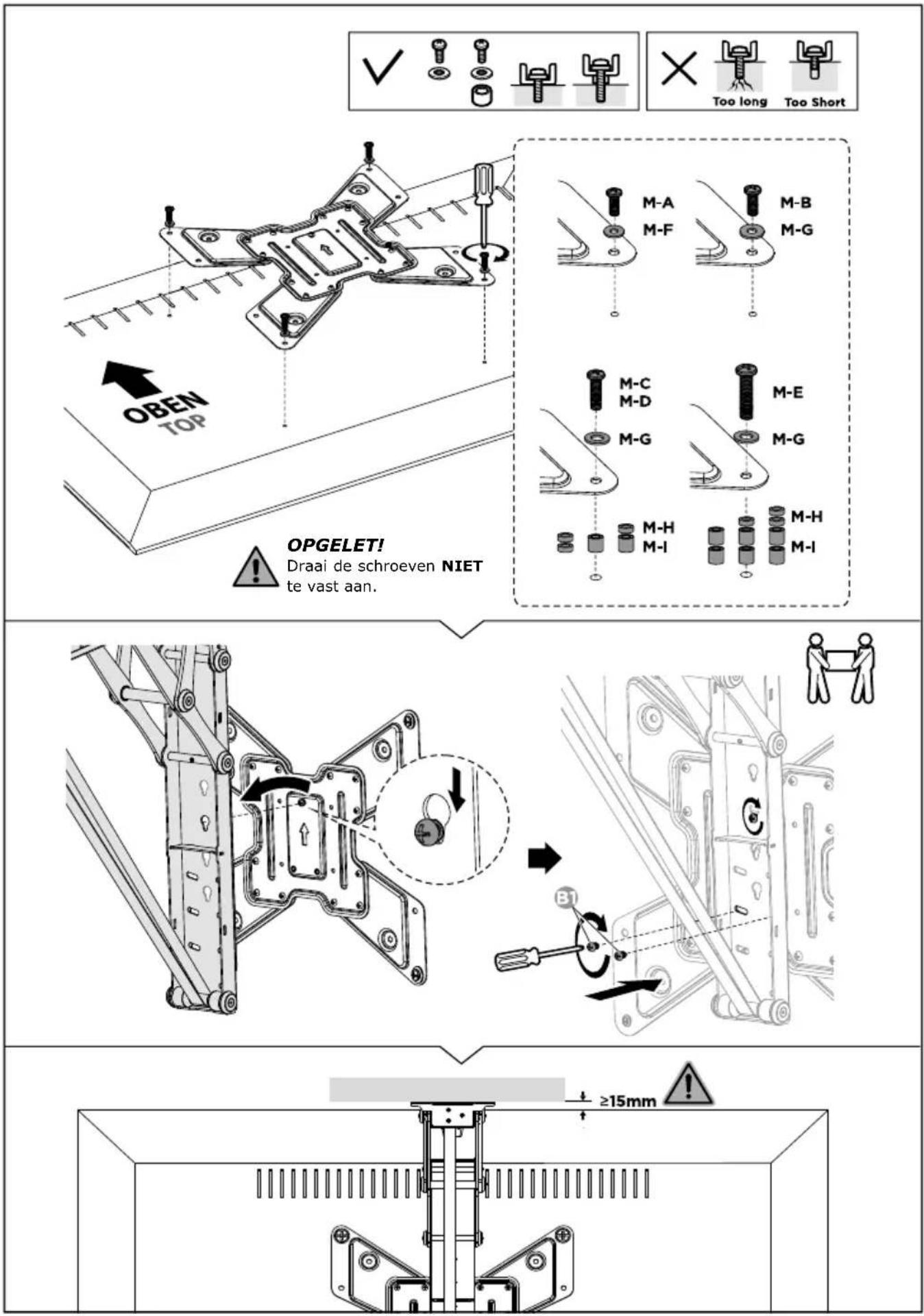
• Always have another person assist you or use a mechanical lifting device to safely lift and position the unit. - Tighten the screws, but not too tight. Overtightening may cause damage and reduce significantly the load-bearing capacity of the screws.
- This product is intended for indoor use only. Use of this product outdoors may lead to product defects and personal injury.
- Do not disassemble or modify the electronic components of the product without permission.

WARNING!
R
Faulty electrical installation or excessive mains voltage can lead to electric shock.
- The device may only be used with the supplied mains adapter. Modifications to the supplied mains adapter are not permitted.
- Never use the system if the power cord or plug is damaged. If any part is damaged, please contact your dealer for a replacement part.
- Never use the system in a humid environment or when its electrical parts have been in contact with liquids.
- Do not clean the unit when it is still connected to the mains.
- Do not disassemble or replace any parts while the unit is still connected to the mains.
- Unplug the unit from the mains when not in use and keep it out of the reach of children.

WARNING!
- This product can be used by children aged from eight years and above and persons with reduced physical, sensory, or mental capabilities or lack of experience and knowledge if they have been given supervision or instruction concerning use of the product in a safe way and understand the hazards involved. Children must not play with the product. Cleaning and user maintenance must not be carried out by children without supervision.
- Keep children younger than eight years away from the product and the connecting cable.
- Do not leave the product unattended during operation.
- Do not allow children to play with the packaging film. Children can get caught in it while playing and suffocate.

WARNING!
I
- Keep batteries out of the reach of children. Children could put batteries in their mouths and swallow them. If a battery is swallowed, seek medical attention immediately.
- Do not dispose of batteries in fire. Do not expose batteries to high temperatures.
- Danger of explosion! Do not charge batteries.
- Do not open or short-circuit batteries.
- Battery acid leaking from a battery may cause skin irritation. In case of skin contact, rinse with plenty of water. If the liquid has got into the eyes, rinse thoroughly with water, do not rub, and consult a doctor immediately.
ER I I DE I
i IMPORTANT:
R
The product can become quickly damaged if you do not take care when opening the packaging with a sharp knife or other sharp objects.
- Open the packaging very carefully.
- Remove the product from the packaging.
-
Check that the supply package is complete.
-
Check that the product or individual parts are not damaged. If anything is damaged, do not use the product. Contact the hotline or e-mail address given in this operating manual.
RE R I S R I S I

CAUTION!
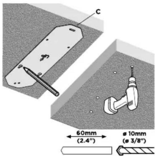
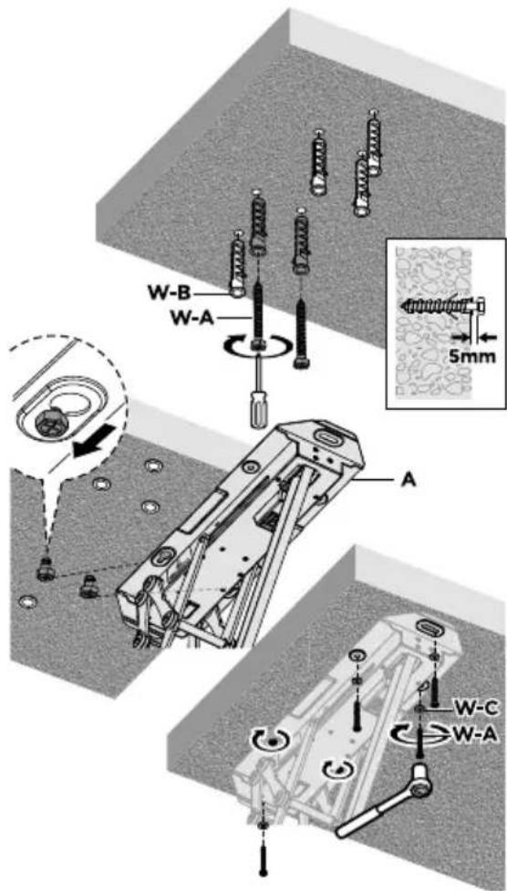
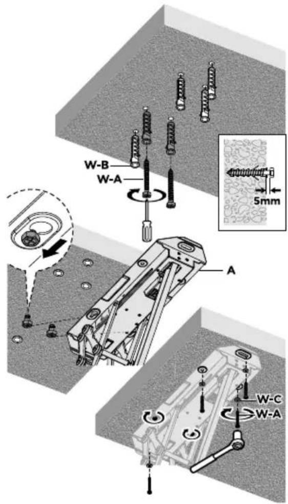
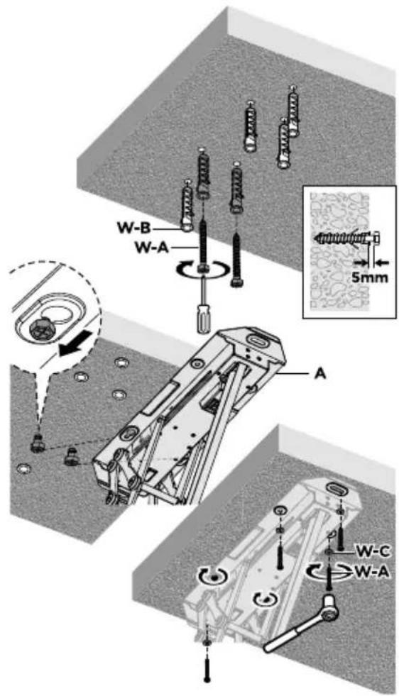
The product should be mounted to a supporting ceiling structure. Observe the type of ceiling when mounting. Installation is only permitted if the type of ceiling is suitable for this purpose. Thin lightweight materials or plasterboard, even on sloping ceilings, are usually unsuitable. Specialised shops, however, may have special screw plugs for such mounting locations. If in doubt, have the mounting carried out by a specialist. Depending on the surface (e.g. wood), suitable fastening materials should be used (only screws without plugs, etc.).
Due to the overall weight of the mounted product and the leverage effect, care must be taken to ensure a stable installation. Always determine the load-bearing capacity of the underlying structure. This structure must be able to support at least 10 times the maximum weight of the ceiling bracket and the installed screen to ensure adequate safety.
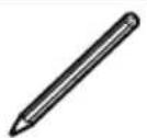
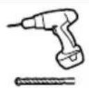
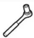
- Plan the installation location carefully so that the TV bracket with the screen attached to it is later at the desired height and position.
- Use a spirit level for mounting.
E I D
| Article number | LWHDS5530 513 |
| Mounting dimensions according to VESA standard in mm | 100x100 200x200 300x300 400x200 400x400 |
| Usable screen diagonal | 23" - 55" (140 cm max.) |
| Load capacity | up to max. 30 kg |
| Cable length Power supply unit | 1,2 m |
| S | R | EU |
| Manufacturer's name or trade mark, commercial registration number and importer, address | Schwaiger GmbH, HRB12220Würzburger Straße 17, 90579 Langenzenn | |
| Manufacturer, address | NINGHAI YINGJIAO ELECTRICAL.,LTD.Cuijia, Xidian Town, Ninghai, zhejiang 315613, China | |
| Model number power supply | YS35-2401500 | |
| Input voltage | 100 – 240 V AC | |
| Input AC frequency | 50/60 Hz | |
| Output voltage | 24.0 V DC | |
| Output current | 1.5 A | |
| Output power | 36.0 W | |
| Average active efficiency | 87.7 % | |
| Efficiency at low load (10 %) | 84.2 % | |
| No-load power consumption | 0.1 W | |
UIG


WARNING!
- It is the installers' responsibility to provide fixings for other types of mounting.
- The installer must ensure that the surface can support the total weight of the device and all parts and components attached to it.
- The installer must ensure that screws and plugs suitable for the surface are used.
D S R REE
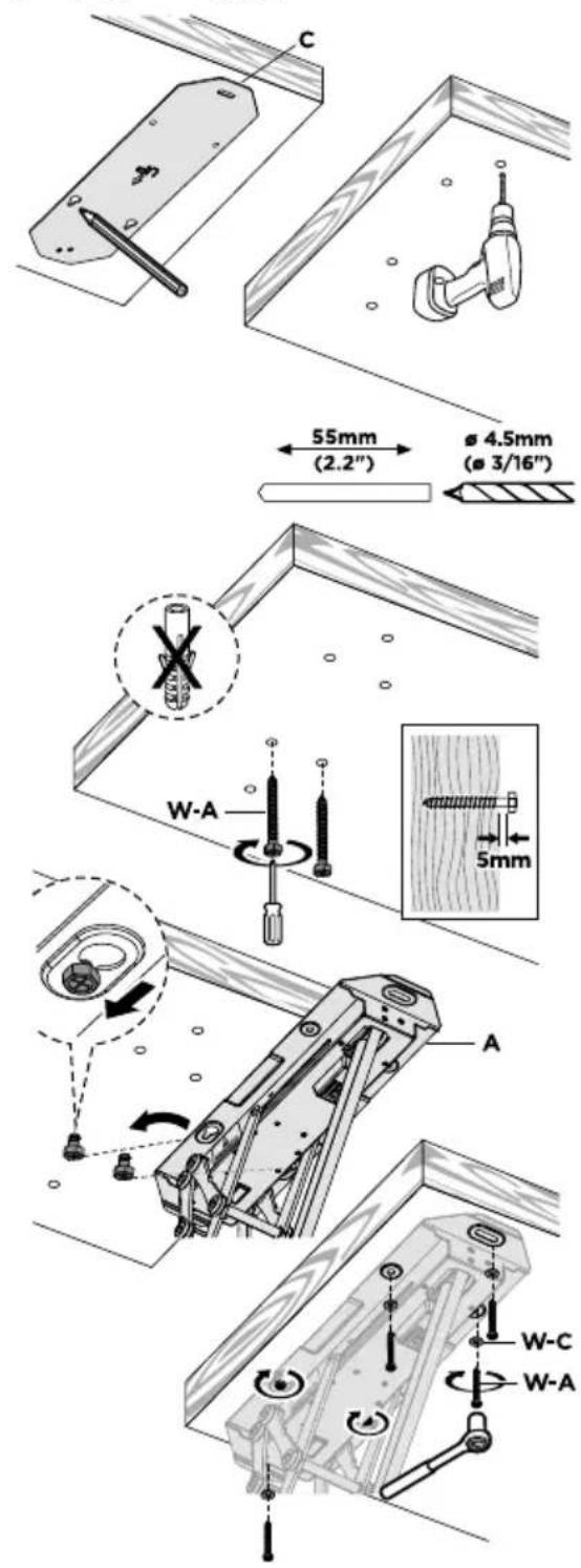
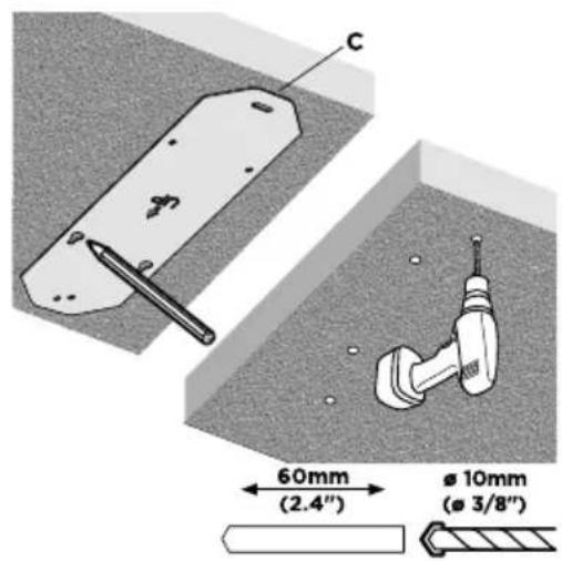
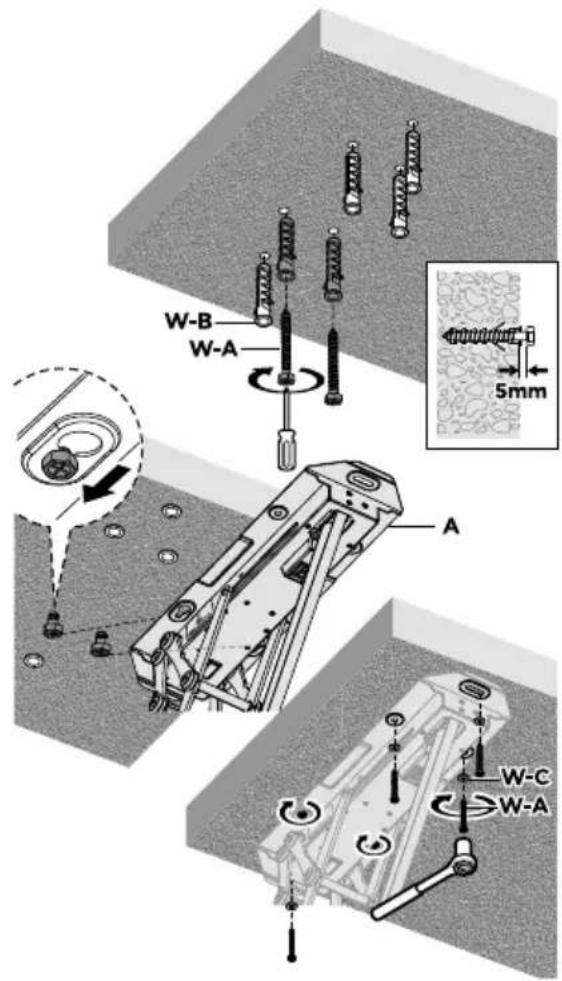
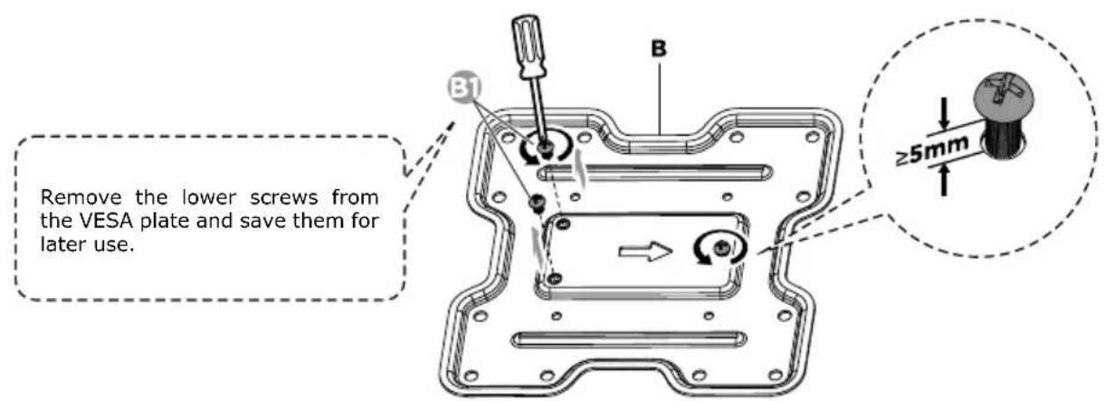
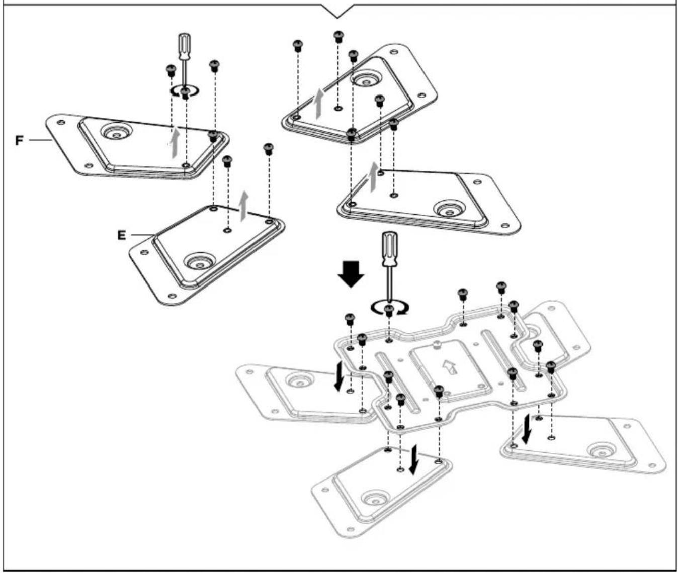
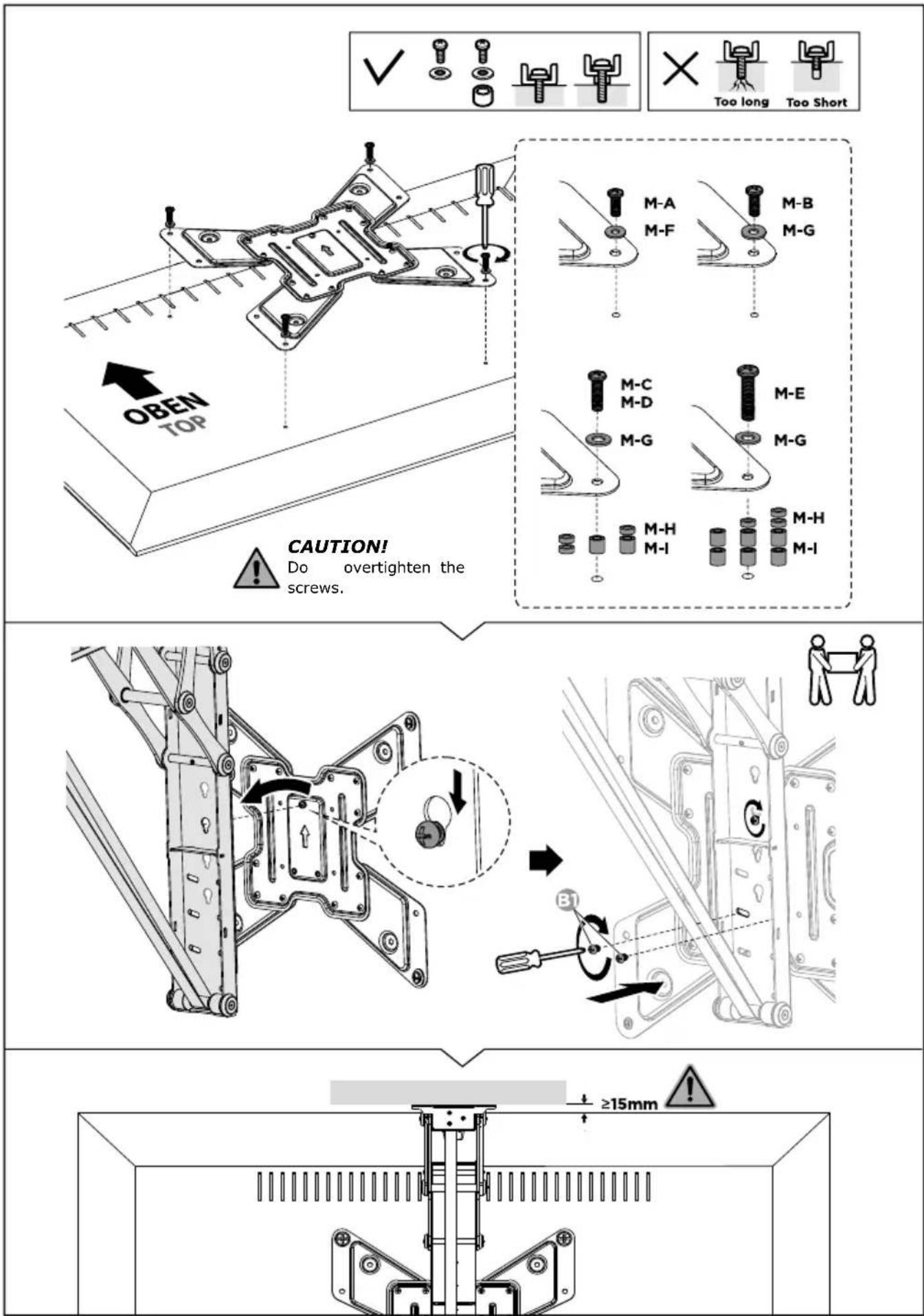
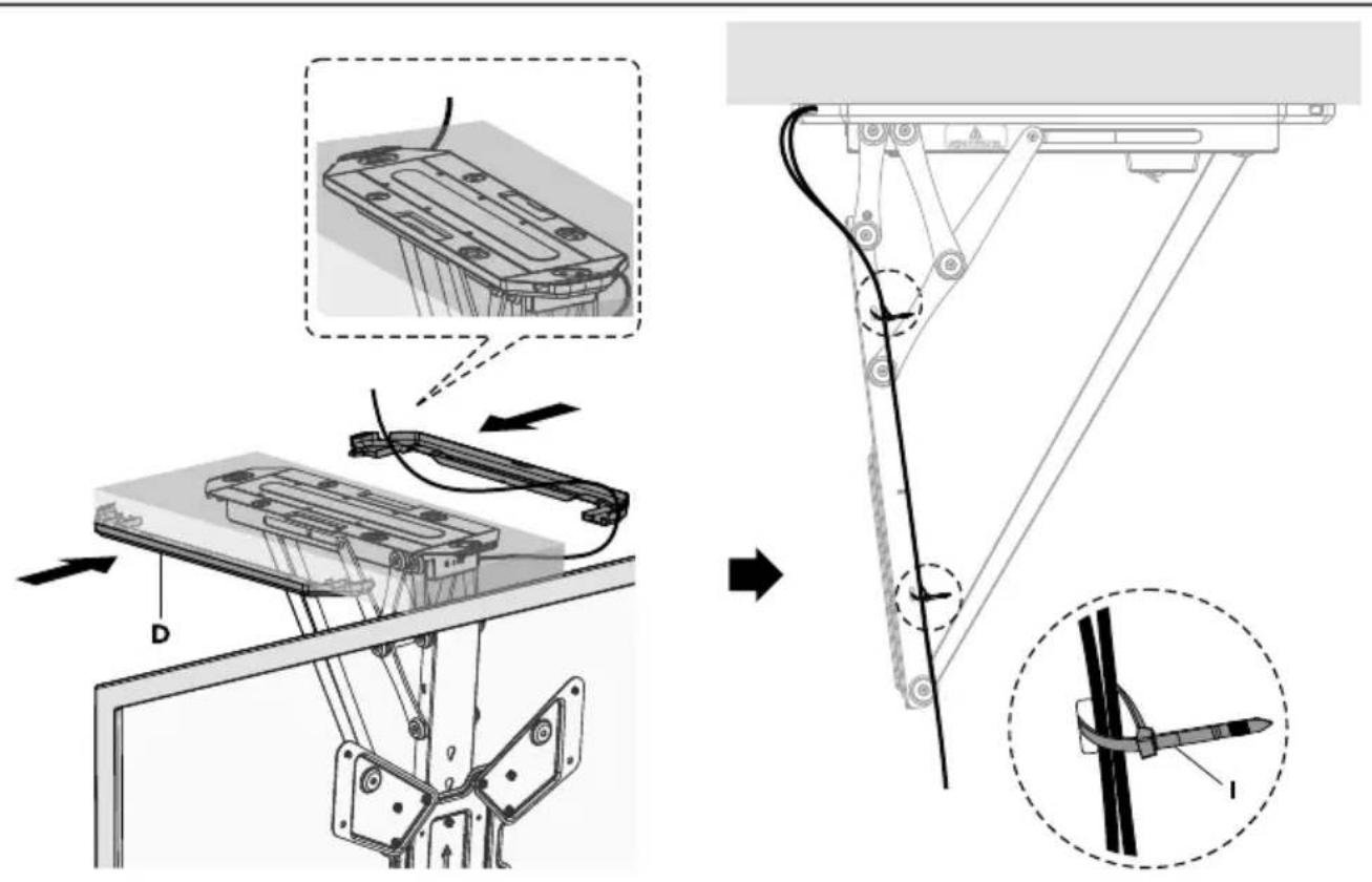

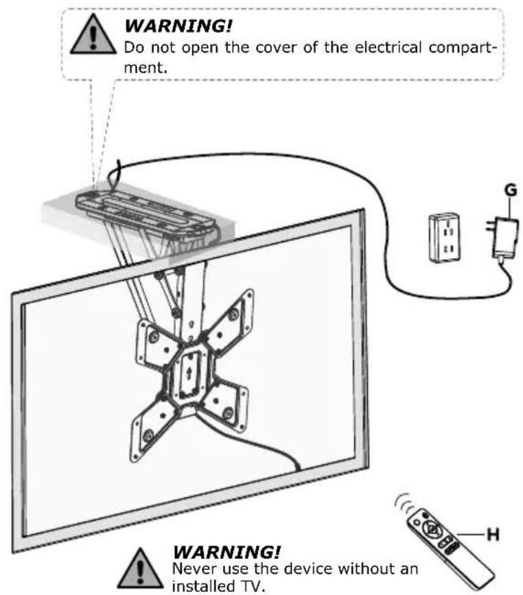
WARNING!
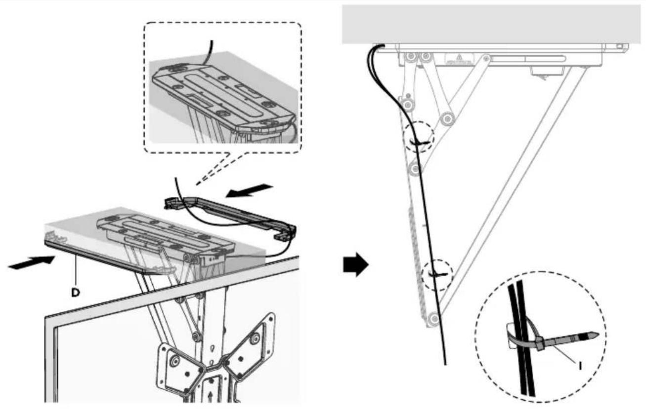
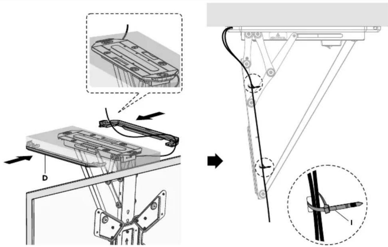
The movement area of the bracket should not be blocked by objects.
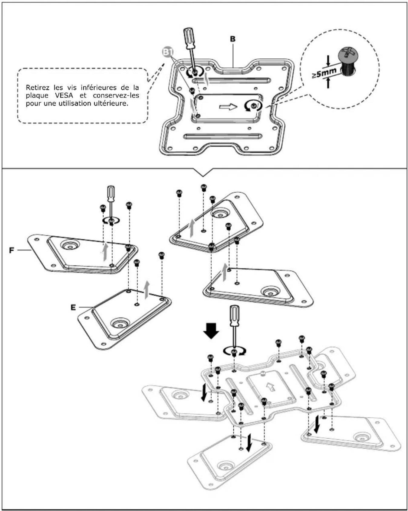
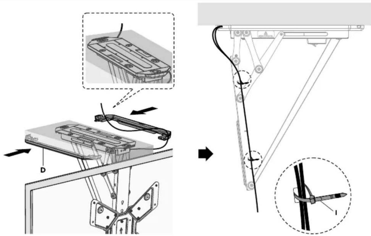
Use the cable ties to secure the cables.
NOTE: Allow clearance at the cables for arm movement
natural_image
Two hand-drawn diagrams showing a folded document or template with arrows indicating rotation (no text or symbols)RE E R
U D
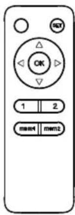
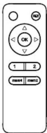
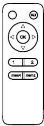
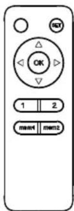
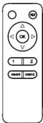
When the △button is pressed, the TV bracket moves up to the position closest to the ceiling. Upon pressing the ▽button, the TV bracket will move down to the position with the maximum tilt angle (default 75°). Press the ⬇button to stop the movement. (Remove all obstacles from the movement area).
Press and hold the mem1 or mem2 button for 1 second and you will hear a beep indicating that the current position has been stored in memory. The or buttons can always be used to store another position.
Press the 1 or 2 button and the TV bracket will automatically move to the position stored under the room or button.
R
If the TV bracket cannot be set to the highest position (0 degrees to ceiling) or lowest position (maximum tilt), unplug the power cord and plug it back in. Then press and hold the button for 5 seconds. The TV bracket will return to the highest position, i.e. the system has reset successfully.
S
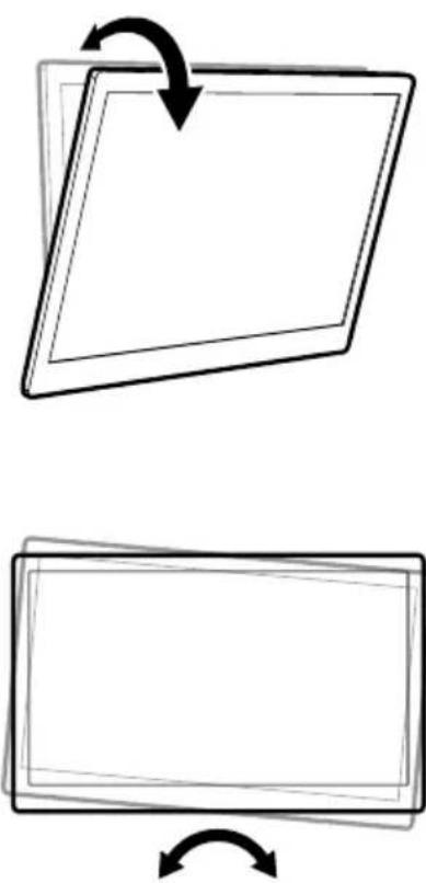
The TV bracket can be adjusted from 0° to 75° as standard. Please set the tilt range when using the TV bracket on a sloping ceiling.
Reset the system (see the instructions under A. Button functions - 4. Reset).
S Press the △, ▽ and Ⓞ buttons and set the correct position.
S Press and hold the button until the unit beeps once. Repeat this step 5 times. The unit will emit a long beep to indicate successful setting.
Steps 1 and 2 must be completed within 2 minutes or the unit will not be set. The remote control requires two AAA batteries ( ).
If you manually raise the TV ceiling bracket to any position (except the minimum position against the ceiling), it will automatically return to the minimum position against the ceiling.
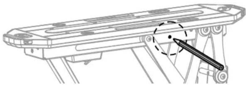
S With the bracket switched on, press the small button on the control unit with a thin tool as shown. The device will beep to indicate that the control unit is ready for encoding.
S Press the button on the remote control and the control unit will beep repeatedly for about 10 seconds, indicating that the remote control is being programmed. The process will be completed automatically until no beep is heard.
natural_image
Technical line drawing of a mechanical assembly with a sliding guide and lever mechanism (no text or symbols)The TV bracket can be paired with up to 20 remote controls. To delete all remote controls, press and hold the code setting button for 5 seconds and then release it. The device will beep twice to confirm successful deletion, otherwise deletion is not done.
R U ES I G
This troubleshooting guide is intended to help you identify and solve minor problems caused by the unusual operation of our electric TV bracket. The simple procedures in this guide are easy to follow and can solve most problems encountered in everyday use.
Reset the system by following the instructions.
(New batteries run out after 24 hours without the remote controller being used). Please contact us.
Check the batteries.
(Operating range is less than 3 m): Replace the batteries.
Reset the system by following the instructions.
Check if the mains adapter is properly connected to the product. If it is, please turn on the unit. If you do not hear a buzzer tone or see a red power indicator, check if the mains adapter is working properly. If the mains adapter does not work, please contact us. Contact us if the mains adapter works properly but the TV bracket does not.
Please contact us.
D

Do not dispose of batteries or electric and electronic devices in the normal household waste. The consumer is legally obliged to return electrical and electronic devices and batteries that are at the end of their useful life to the point of sale or public collection points that have been set up for this purpose. Legislation in the country of use governs individual details regarding disposal. The symbol on the product, the user guide or the packaging indicates
this legal requirement.
D
Schwaiger GmbH does not accept any liability or warranty for damages that are sustained due to improper installation or mounting, improper use of the product or non-compliance with the safety instructions.
Dear Customer,
Please contact our Technical Support if you need technical advice and your retailer is unable to help you.
The warranty period starts when the product is purchased. The purchase receipt, such as a till receipt, invoice or delivery slip, serves as proof of this date. Keep these documents in a safe place. Our warranty is based on our warranty conditions valid at the time of purchase.
S G
Monday to Friday: 8:00 a.m. - 5:00 p.m.
CE
L
L
natural_image
Technical line drawing of a mechanical assembly with no visible text or symbols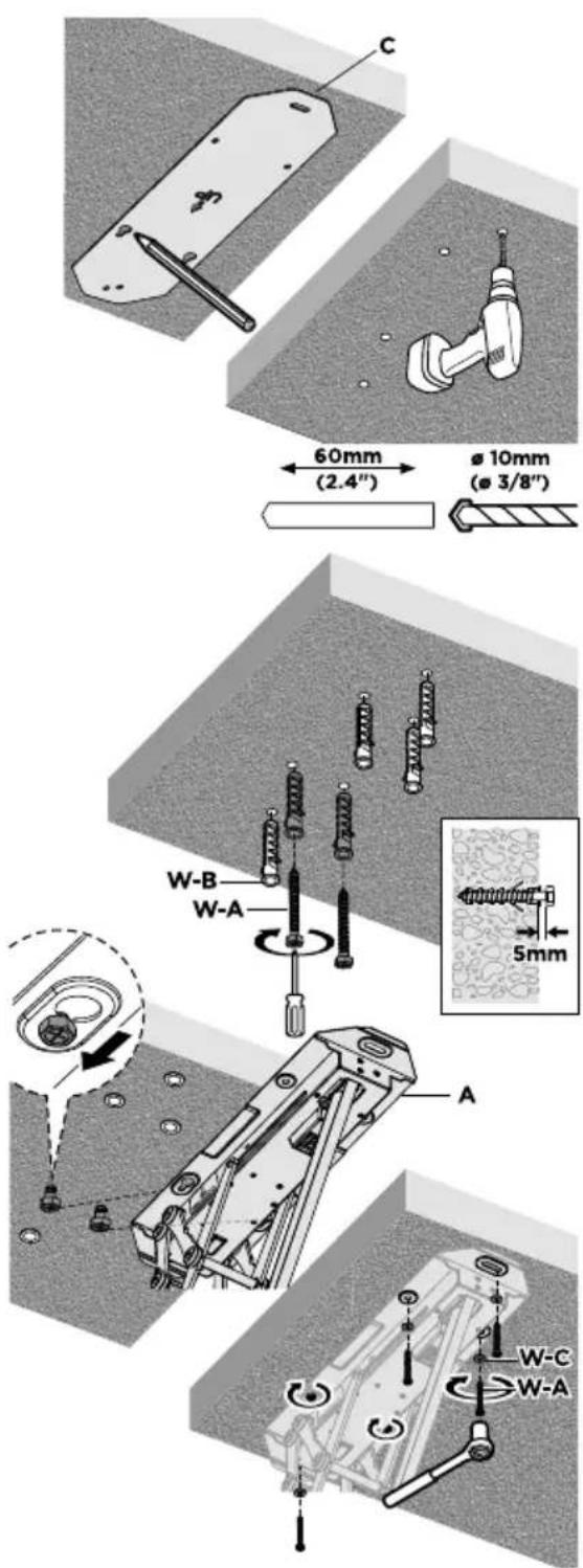

AVERTISSEMENT !
natural_image
Two blank rectangular panels with curved arrows indicating rotation or transformation (no text or symbols)L OMM DE
M
natural_image
Technical line drawing of a mechanical assembly with a hand operating a sliding component (no text or symbols)P EP I I PE L I LL IO E

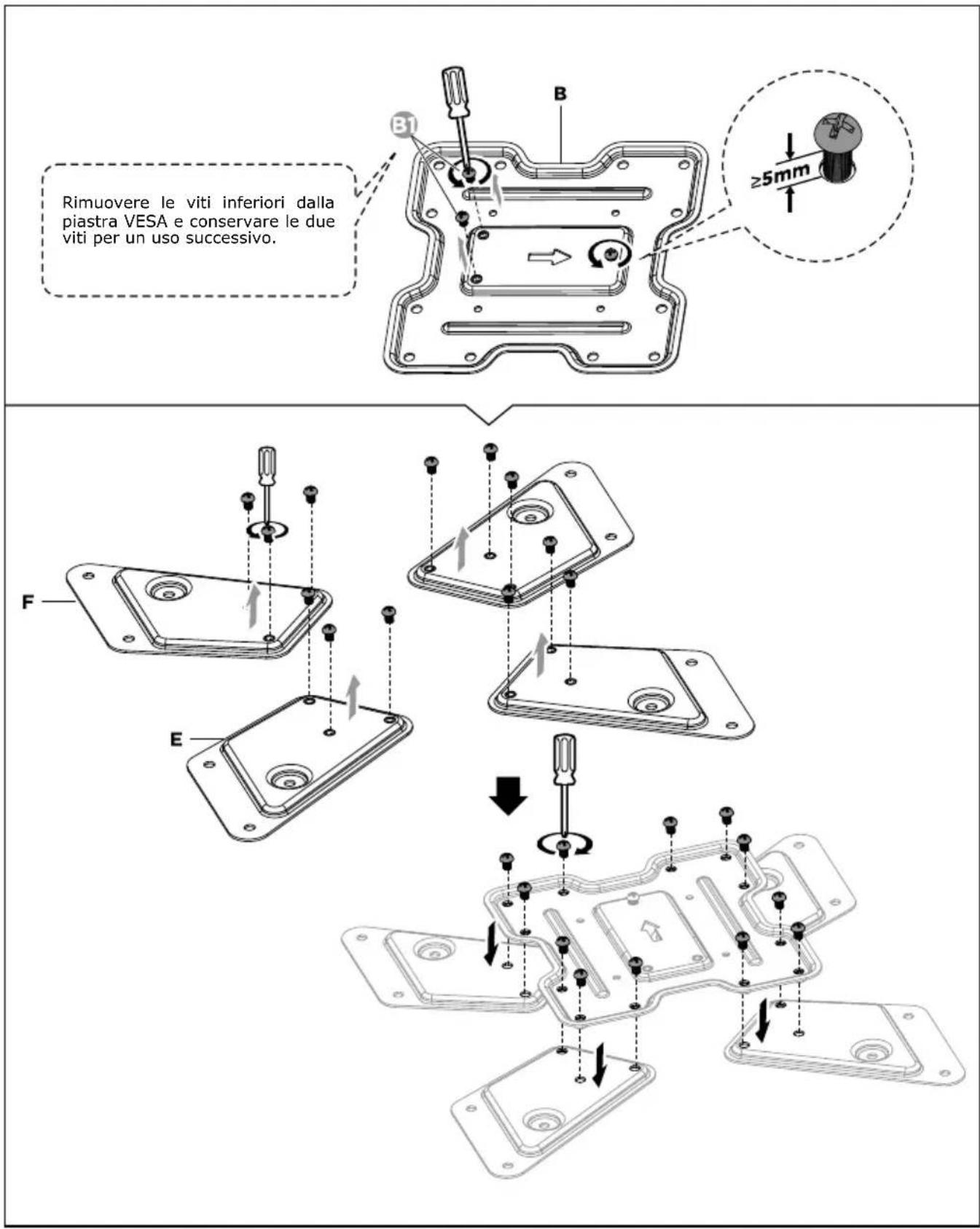
ATTENZIONE!
P


AVVERTENZA!
natural_image
Two-step diagram showing a square object being rotated by a curved arrow, with no text or symbols present.ELE OM DO
M
natural_image
Technical line drawing of a mechanical assembly with a hand operating a lever (no text or symbols)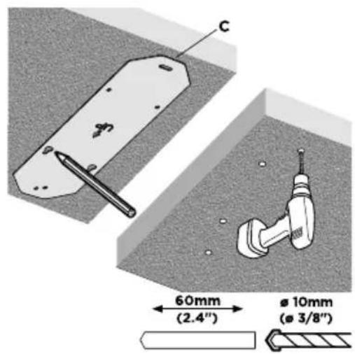

WAARSCHUWING!
natural_image
Two blank rectangular panels with arrows indicating rotation, no text or symbols presentASTANDSBEDIENING
A
N
natural_image
Technical line drawing of a mechanical assembly with a sliding guide and lever mechanism (no text or symbols)
Brand : Schwaiger
Model : LWHDS 5530
Category : Wall mount