
LWH031 031 - Wall mount Schwaiger - Free user manual and instructions
Find the device manual for free LWH031 031 Schwaiger in PDF.


| Product Type | Fixed Wall Mount |
| Compatible Screen Sizes | 32 – 65 inches |
| Maximum Weight Capacity | 50 kg (110 lbs) |
| VESA Patterns Supported | 100x100 mm to 400x400 mm |
| Distance from Wall | About 20 mm (low profile) |
| Material | Cold-rolled steel, powder coated |
| Color | Black |
| Dimensions (W x H x D) | 450 x 250 x 30 mm |
| Net Weight | 2.1 kg |
| Included Hardware | Screws, wall anchors, spacers, bubble level, user manual |
| Tilt Adjustment | No (fixed mount) |
| Swivel / Rotation | No |
| Installation Requirements | Drywall, concrete, or brick wall; studs recommended |
| Safety Features | Anti-drop safety tabs, level indicator |
| Cleaning Instructions | Wipe with dry cloth; avoid solvents |
| Repairability | No user-serviceable parts; replace if damaged |
Frequently Asked Questions - LWH031 031 Schwaiger
User questions about LWH031 031 Schwaiger
0 question about this device. Answer the ones you know or ask your own.
Ask a new question about this device
Download the instructions for your Wall mount in PDF format for free! Find your manual LWH031 031 - Schwaiger and take your electronic device back in hand. On this page are published all the documents necessary for the use of your device. LWH031 031 by Schwaiger.
USER MANUAL LWH031 031 Schwaiger
natural_image
Mechanical device with a star-shaped handle and cylindrical shaft, shown in black and white (no text or symbols visible)LWH 031
natural_image
Hand holding a screwdriver inserted into a device with a close-up of its internal components (no text or symbols visible)natural_image
Close-up of a metallic pipe fitting with a circular opening and a hole, against a plain background (no text or symbols visible)natural_image
Technical line drawing of a mechanical assembly with labeled component D (no text or symbols present)D
natural_image
Mechanical component with metallic shaft and mounting base, labeled 'lung' (no other text or symbols)natural_image
Metal mechanical component with four arms and a central hole (no text or symbols visible)4. Technische Daten
D




Content
GB
COMPANY INFORMATION....10
WARNING....12
Safety Notes 12
Hardware kit 13
Tools Required....13
- Mounting the Wall Plate....14
1.1 Wood Stud Installation....14
1.2 Concrete/Brick Installation....14 - Attaching the Arm to the LCD 15
- Final Installation and Operation....16
3.1 Final Installation....16
3.2 Operation and Adjustment....16 - Technical Data....17
COMPANY INFORMATION
Dear customer,
In case you will need further technical support and your dealer is not available please contact our help line:
Schwaiger GmbH
Würzburger Straße 17
90579 Langenzenn
Hotline: +49 (0) 9101 702-299
www.schwaiger.de
info@schwaiger.de
Opening hours
Monday to Thursday: 08:00-17:00 h
Friday: 08:00-14:30 h
WARNING
- Do not begin the installation until you have read and understood the instructions and warnings contained in this installation sheet. If you have any question regarding any of the instructions or warnings, please contact your local distributor.
- This mounting bracket was designed to be installed and utilised ONLY as specified in this manual. Improper installation of this product may cause damage or serious injury.
- This product should only be installed by someone with good mechanical ability who has based building experience and fully understands this manual.
- Make sure that the supporting surface will safely support the combined weight of the equipment and all attached hardware and components.
• Always use an assistant or mechanical lifting equipment to safely lift and position the equipment. - Tighten screws firmly, but do not over tighten. Over tightening can cause damage to the items, This greatly reduces their holding power.
- This product is intended for indoor use only. Using this product outdoors could lead to product failure and personal injury.
GB
Safety Notes
If you have doubts about a safe installation, have it installed by a qualified technician.
SCHWAIGER can not be held responsible for damage or injury caused by improper installation or improper use.
Note: The included mounting hardware is only suitable for solid wall/ceiling construction. If you are not sure of the condition of the existing wall/ceiling in mind, consult a specialist. The included hardware is not suitable for steel.
Tools Required
Phillips Head Screw driver
Stud finder for drywall installation
Electric drill and 1/4" (8mm) masonry bit for concrete/brick installation
Note: You need to insert the bubble level system when you install the wall plate and take it away fate you finish installation.
IMPORTANT:
Ensure that you have received all parts according to the component checklist prior to installation. If any parts are missing or faulty, telephone your local distributor for a replacement.
Hardware kit
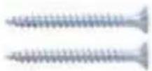
50 mm (2x) Wood Screw
A
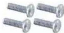
M4 x 12 mm (4x) Head Screw
B
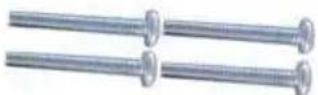
M4 x 30 mm (4x) Head Srew
C
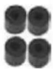
16 mm (4x) Spacer
D
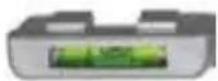
Bubble Level System
E
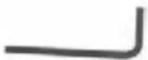
S = 5 mm Allen Wrench
F
1. Mounting the Wall Plate
1.1 Wood Stud Installation
- Place the wall plate against the wall with towards the bottom.
- Secure the wall plate using one 2" wood screw (A).
- Using the bubble level system (E), carefully wall plate until it is level.
- Attach the remaining 2" wood screw into the wall plate and tighten.
Note: Using a wood stud finder, locate the stud centers behind the wall. Once found, make a pencil marking on the center of the wood studs.
Once the mark is made, it is strongly recommended that a pilot hole be drilled with a 1/8" drill bit.
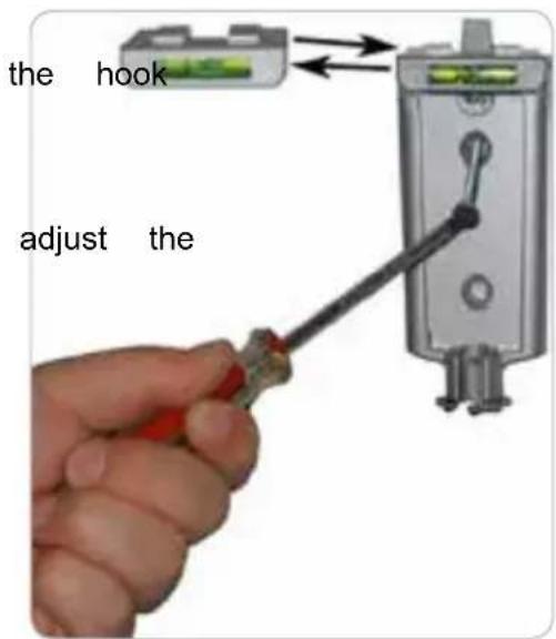
1.2 Concrete/Brick Installation
Note
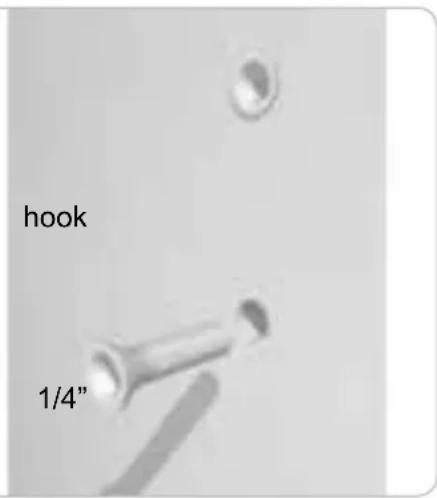
1/4"(8mm) anchor must be used for concrete installation. They can be purchased at your local hardware store.
- Place the wall plate against the wall with towards the bottom.
2 Level and mark with a pencil the two mounting points found on the wall plate. - Next, drill two holes using an electric drill masonry bit.
- Insert the threshold anchors into the holes that were drilled in the wall.
the hook
and 1/4"
GB
Note: If necessary, use a hammer to lightly tap each anchor into place so that they are flush with the wall.
- Once the anchors are in place, put the wall piece back over the concrete anchors.
- Using a screw driver, attach the back plate by threading the two screws into the anchor which has been recessed into the wall.
- Make sure all screws are snug, but be careful not to over-tighten them.
2. Attaching the Arm to the LCD
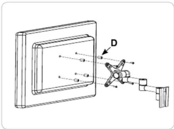
- Determine the mounting hardware that is to be used.
- If your LCD has a flat back, use the M4x12 mm Head Screws (B).
Note: If your LCD has a recessed back, use the longer M4x30mm Phillips Head Screws (C) and 3/4" spacers (D).
- After you have determined the appropriate screws, use them to attach the mounting plate to the back of your LCD
- Do not over-tighten the screws.
natural_image
Technical line drawing of a mechanical assembly with labeled component D (no text or symbols present)GB
3. Final Installation and Operation
3.1 Final Installation
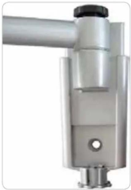
- To complete the installation, simply slide the arm piece onto the wall plate.
- The plastic tab on the top of the wall piece should click, indicating that the arm piece is secure.
- If you need to remove the arm piece, push in on the tab and slide the arm up.
- For additional security and stability, tighten the security bolt located on base of the arm piece using the Allen Wrench (F) included in the hardware kit.
natural_image
Close-up of a metallic mechanical component with a black knob and cylindrical shaft (no visible text or symbols)3.2 Operation and Adjustment
Note: Adjustment of your LCD may vary by model
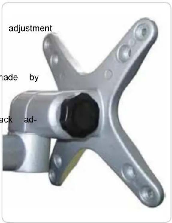
On most models, the tilt angle of your LCD can be adjusted by first loosening the gear joint that holds the tilt in place. To do this, locate the knob directly behind the LCD mounting point.
Loosen it by turning the knob counter-clockwise.
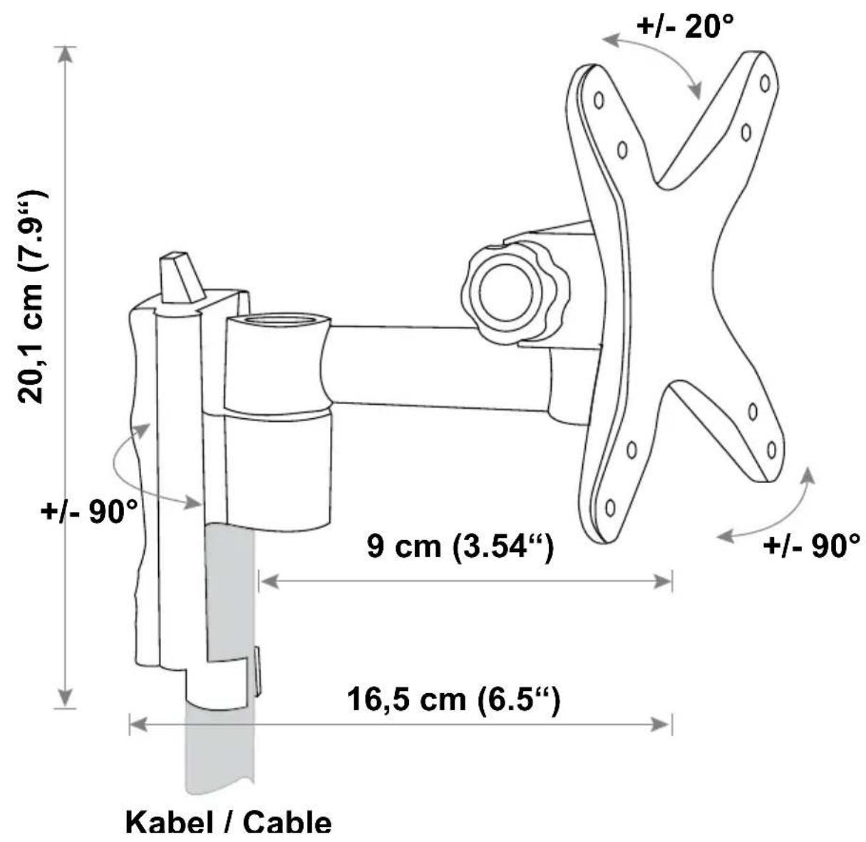
Adjust the tilt to the desired level and re-tighten the knob. Other viewing adjustments can be simple moving the arm into the desired position. If you find that a joint is too difficult to move or does not hold the LCD in place, you can adjust the tightness of the joint. If your mount includes justment knobs, turn a knob clockwise to tighten and counter-clockwise to loosen. If your mount does not have knobs, use the Allen Wrench (F) to tighten or loosen the joint.
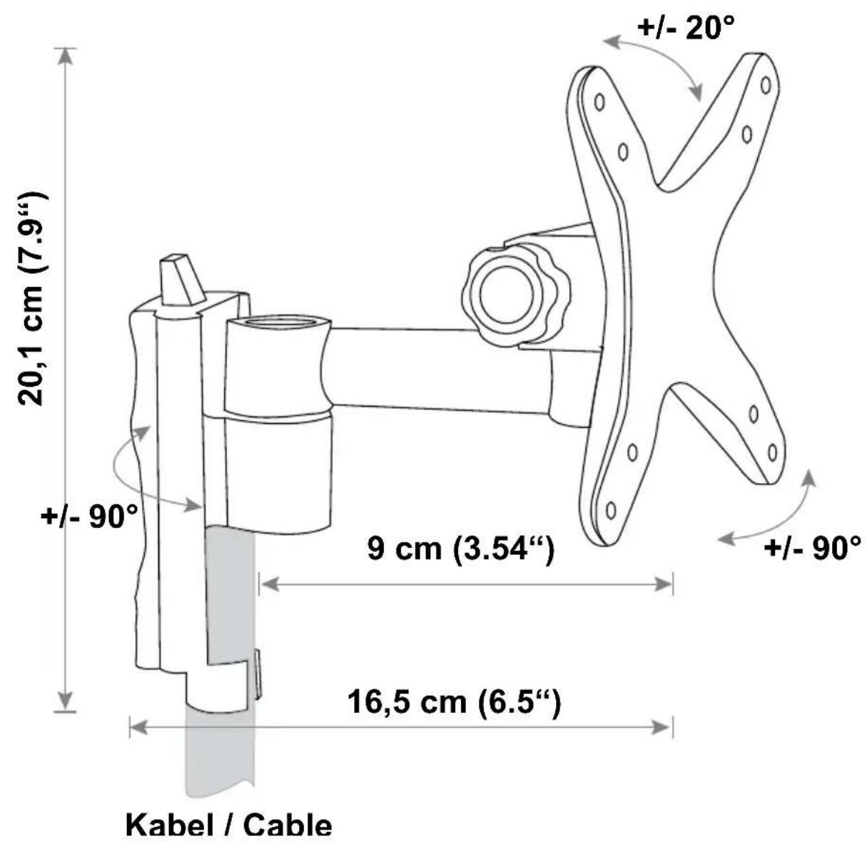
4. Technical Data
GB




Notes
GB
- LWH 031
- D
- Technische Daten
- Content
- GB
- COMPANY INFORMATION
- Opening hours
- WARNING
- Safety Notes
- Tools Required
- IMPORTANT:
- Hardware kit
- Mounting the Wall Plate
- Wood Stud Installation
- Concrete/Brick Installation
- Note
- Attaching the Arm to the LCD
- Final Installation and Operation
- Final Installation
- Operation and Adjustment
- Technical Data
- Notes
Brand : Schwaiger
Model : LWH031 031
Category : Wall mount