
Outdoor 40 Sat - Speaker Martin Logan - Free user manual and instructions
Find the device manual for free Outdoor 40 Sat Martin Logan in PDF.


| Product Type | Outdoor satellite speaker |
| Brand | Martin Logan |
| Model | Outdoor 40 Sat |
| Category | Audio speaker |
| Material | UV-treated ABS plastic |
| Usage | All-weather outdoor |
| Speaker Type | Passive |
| Impedance | 8 ohms (adjustable via dial) |
| Nominal Power | 30 W (max on 70 V tap) |
| Frequency Response | Not specified |
| Sensitivity | Not specified |
| Recommended Amplifier | Crown CDi 1000 (or 8 ohm amplifier) |
| Mounting Options | Ground stake, surface mount, underground junction box (sold separately) |
| Recommended Cable | 4-conductor underground cable |
| Cable Gauge | 18 to 10 AWG depending on distance (up to 198 m) |
| Included Accessories | Mounting arm, 2 silicone-filled cable caps |
| Warranty | 90 days automatic, 3 years after online registration |
| Power | Passive (requires external amplifier) |
| Maintenance | Clean with a soft, dry cloth. Avoid abrasive products. |
| Safety | Watch for electrical wires, gas lines, and underground cables before digging. |
| Repairability | Contact an authorized MartinLogan dealer for any repairs. |
Frequently Asked Questions - Outdoor 40 Sat Martin Logan
User questions about Outdoor 40 Sat Martin Logan
0 question about this device. Answer the ones you know or ask your own.
Ask a new question about this device
Download the instructions for your Speaker in PDF format for free! Find your manual Outdoor 40 Sat - Martin Logan and take your electronic device back in hand. On this page are published all the documents necessary for the use of your device. Outdoor 40 Sat by Martin Logan.
USER MANUAL Outdoor 40 Sat Martin Logan
OUTDOOR LIVING SERIES
by MARTIN LOGAN®
Register your warranty online at www.MartinLogan.com.
TABLE OF CONTENTS
Overview .... 3
MartinLogan Outdoor Living Series Satellite Speakers . . . 3
Required Tools 3
Power 3
Planning The Install 4
Wiring Recommendations .... 5
Installation Considerations .... 5
Wiring & Speaker Installation ..... 6
Mono Setup Using 4 Conductor Burial Cable & Crown Amplifier....6
Preparing the 4 Conductor Burial Cable ..... 6
Installing Ground Stake Accessory & Attaching Speaker 7
Installing Surface Mount Bracket Accessory & Attaching Speaker 9
Speaker & Burial Cable Connections ..... 11
Speaker Direction & Settings. 11
Optional Inground Conduit Box. 12
OPTION 1: PVC Conduit Installation ..... 12
OPTION 2: Burial Cable Installation ..... 12
Test System 13
To Avoid Speaker Damage ..... 14
Listening Outdoors 14
Audio Settings Chart .... 15
Warranty 16
Service....16
OVERVIEW
MartinLogan Outdoor Living Series Satellite Speakers
The MartinLogan Outdoor Living Series satellite speakers are premium sounding all-season outdoor speakers that are ideal for backyards ranging from 2,000 to 3,000 sq. feet.
OUTDOOR SAT 40 and OUTDOOR SAT 60 are sold individually and can be ordered in accordance with the area to be covered.
Made of durable UV treated ABS plastic, MartinLogan Outdoor Living Series speakers can endure the elements while providing years of trouble free service.
While installation is relatively easy, MartinLogan's Outdoor Living Series products are designed to be installed by your authorized MartinLogan dealer.
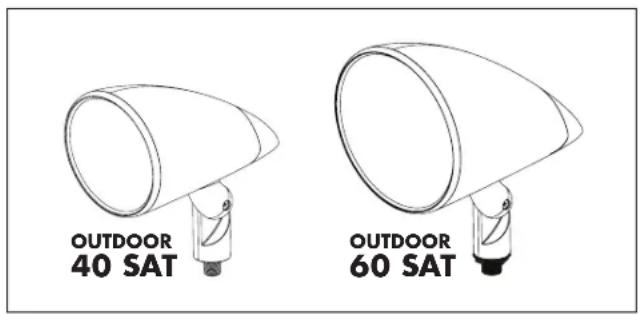
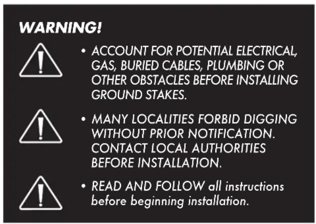
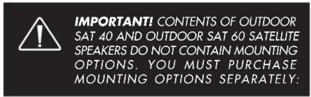
Contents of OUTDOOR SAT 40 and OUTDOOR SAT 60:
• (1) Speaker with Mounting Arm
• (2) Silicone-Filled Wire Connectors
Mounting Options (Sold Separately):
- Ground Stake
- Surface Mount Bracket
- Inground Conduit Box
Required Tools:
- Shovel
- Cable Strippers
• Phillips Screwdriver • Wrench
Power
- Crown Amplifier
The MartinLogan OUTDOOR SAT 40 and OUTDOOR SAT 60 are passive speakers. These speakers are optimized for use with the Crown CDi 1000 amplifier which can be programmed with customized DSP settings for a variety of different speaker/subwoofer installation scenarios. See 'Audio Settings Chart' on page 15.
8 ohm amplifiers can also be used with the MartinLogan Outdoor Living system, however, they will not be able to run the proprietary MartinLogan DSP presets available for the Crown Amplifier. If you use the speakers and subwoofer with an 8 ohm amplifier, we recommend the following:
Satellite Speakers: Wire only one speaker per amplifier channel and set the tap on each speaker to the 8 ohm setting. Note: Do not wire more than one satellite per amplifier channel in 8 ohm mode.
Subwoofer: Wire only one subwoofer per amplifier channel.
PLANNING THE INSTALL
- Identify the location.
• Determine the positioning of subwoofer and satellite speakers. - Dig the trench according to speakers and accessories to be installed.
- The trench should be 6"-8" deep.
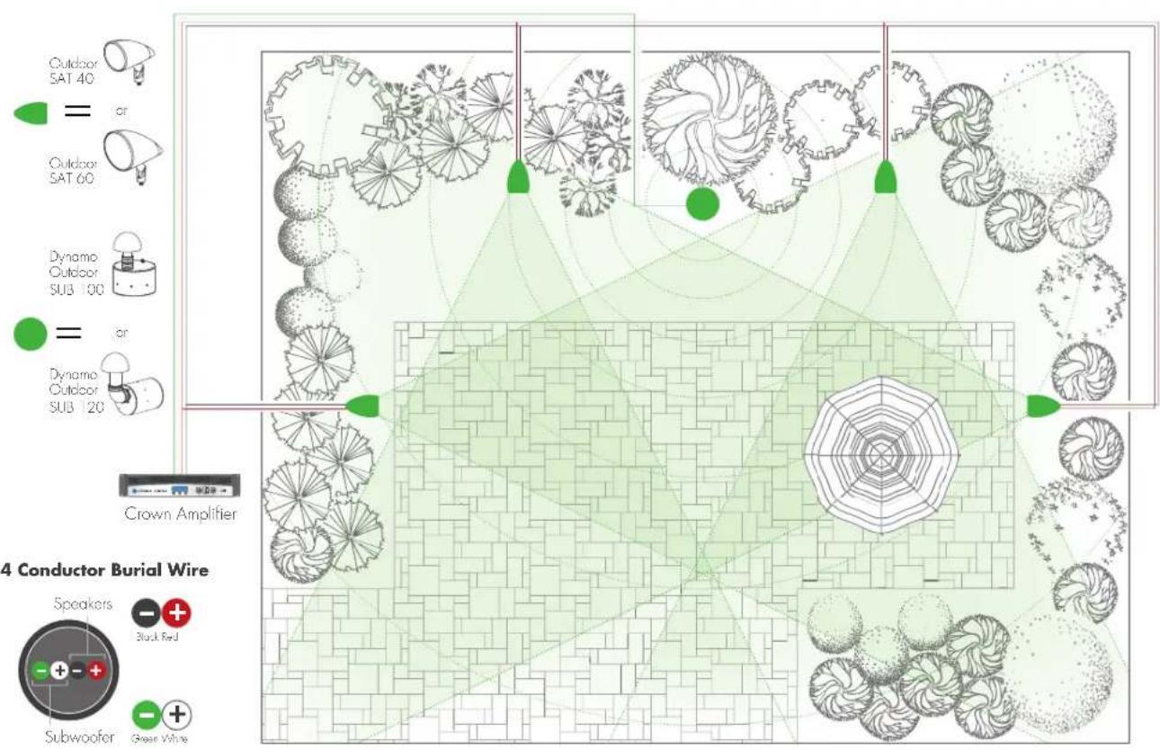
CABLE RECOMMENDATIONS
We strongly recommend using burial-rated cable (not included) when installing any of the Outdoor Living Series Satellite Speakers. In addition, it's critical to use the proper speaker cable gauge. Please review the chart below.
We do not recommend use of smaller cable gauges, as performance will be compromised.
| CABLE GAUGE CHART | |
| Cable Gauge Distance | |
| 18 Gauge Up to 100 feet (30 meters) | |
| 16 Gauge Up to 150 feet (45 meters) | |
| 14 Gauge Up to 200 feet (61 meters) | |
| 12 Gauge Up to 400 feet (122 meters) | |
| 10 Gauge Up to 650 feet (198 meters) |
INSTALLATION CONSIDERATIONS
There a few considerations before you start digging a trench:
- Ensure that ALL Speakers are tested prior to installation.
- Ensure that the proposed area is easily accessed and that the area is not prone to flooding, standing water or where the speakers can be easily damaged, kicked or struck.
- Consider overall landscape/garden design and positioning in relation to listening area
WIRING & SPEAKER INSTALLATION
Mono Setup Using 4 Conductor Burial Cable & Crown Amplifier

Preparing the 4 Conductor Burial Cable
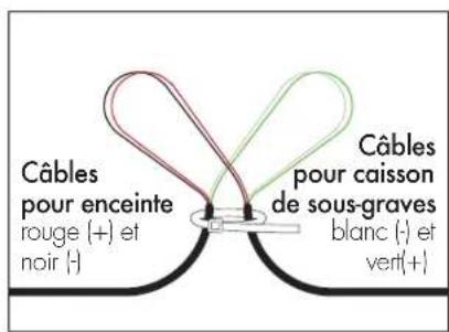
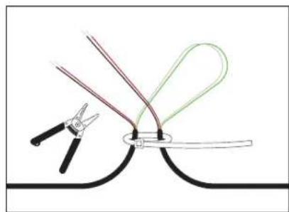
- Starting with the first speaker and every speaker/sub that comes after, create a loop approximately 6" in length.

- Recommended: Use a wire tie (not included) to keep the wire loop intact and act as a strain relief.
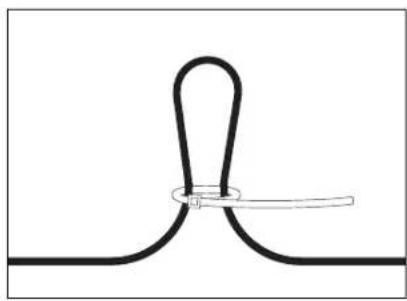
- Use a Round Cable Stripper to remove the outside protective cable jacket to expose the four color-coded wires. Separate the wire loops as shown.
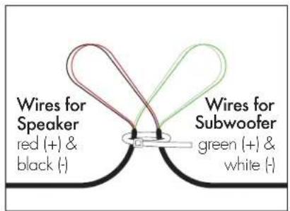
- Cut the red (+) and black (-) wires with cable strippers and strip off 1 inch (25.4mm) of insulation from the ends if the wires to expose the copper conductor.
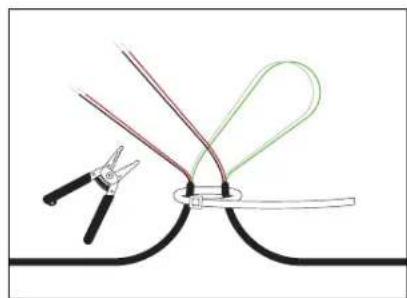
WIRING & SPEAKER INSTALLATION (CONT'D)
Installing Ground Stake Accessory & Attaching Speaker
- Remove nut from the threaded end of the speaker arm.
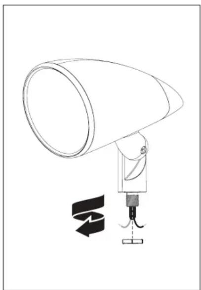
- Remove the twist cap and gas-keted aluminum washer from the ground stake accessory.
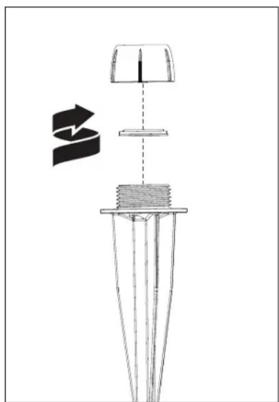
- Slide the twist cap over the speaker arm then slide the gasketed aluminum washer (from the ground stake) over the threaded end of speaker arm.
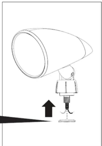
- Using a wrench, thread and firmly tighten the nut (removed in step 1) over the threaded end of the speaker arm.
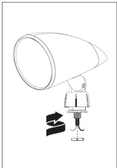
IMPORTANT!
The face of the aluminum washer with the smaller rubber gasket must be facing up.
-
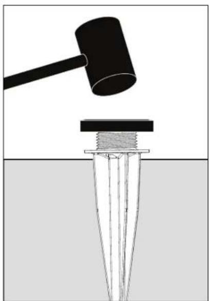
Using a mellet and a wooden block, pound the ground stake into the ground. Drive the ground stake down until the ground stake flange is nearly flush with the surface. Note: Leave a slight gap between the ground stake flange and the ground surface in order to thread speaker wiring through the wiring hole in the ground stake.
-
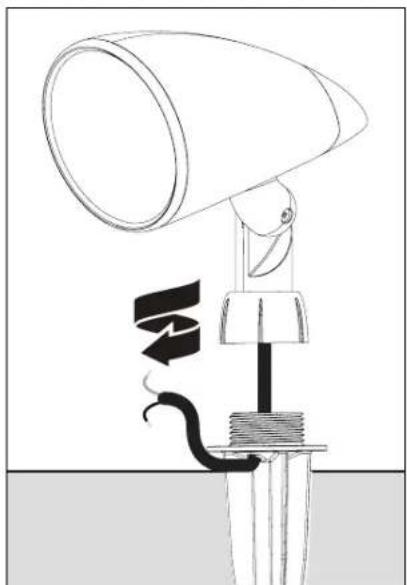
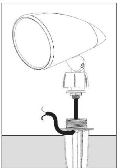
To attach the speaker to the ground stake, hand thread the twist cap to the ground stake.
-
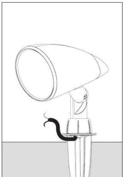
Thread the speaker's wiring through the wiring hole in the ground stake.
-
The speaker is now mounted to the ground stake. The next step is wiring, go the 'Wiring' section for instructions.
WIRING & SPEAKER INSTALLATION (CONT'D)
Installing Surface Mount Bracket Accessory & Attaching Speaker
- Remove nut from the threaded end of the speaker arm.

- Remove the twist cap and gasketed aluminum washer from the surface mount bracket accessory.
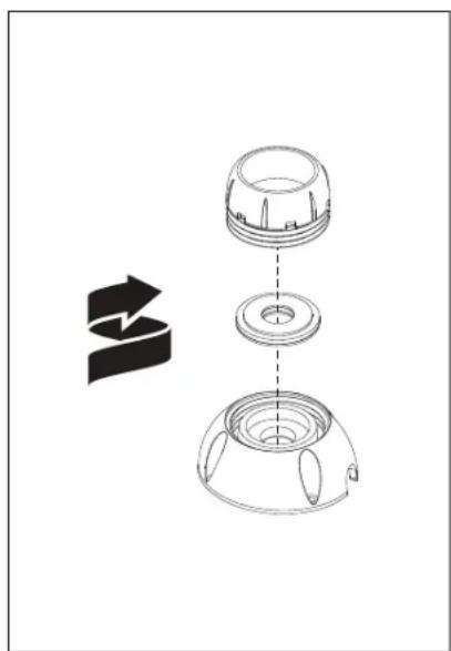
- Slide the twist cap over the speaker arm then slide the gasketed aluminum washer (from the ground stake) over the threaded end of speaker arm.
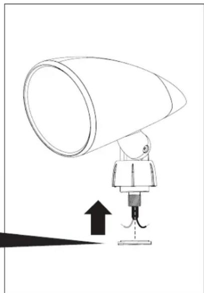
- Using a wrench, thread and firmly tighten the nut (removed in step 1) over the threaded end of the speaker arm.
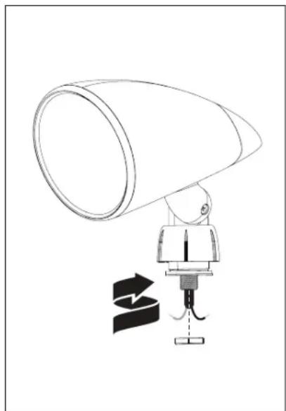
IMPORTANT!
The face of the aluminum washer with the smaller rubber gasket must be facing up.
- Thread the speaker wire through the center hole and out of the wire opening on the surface mount bracket base. Place surface mount bracket base flush against the surface you wish to install your speaker. To attach surface mount bracket base to the surface, use appropriate screws (not supplied) for your installation. For specifications on screws, see your dealer for details.
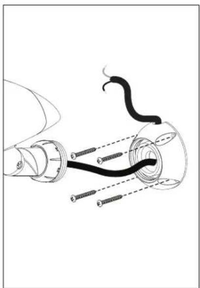
Note: For a wall mounted installation where a wire connection is contained within the surface mount bracket base, please follow these instructions. It is recommend that the speaker wire be cut short and the wire sleeve should be removed to expose the red (+) and black (-) wires. Follow steps 6 a-b, but do not attach the assembled speaker with surface mount bracket base until your wire connections are made with silicone-filled wire connectors covering the exposed wire connections. The wire connections with silicone-filled wire connectors must be stuffed inside the surface mount bracket base before attaching to the desired surface with appropriate screws (not supplied) for your installation. For specifications on screws, see your dealer for details.
- To attach the speaker to the surface mount bracket base; a) First hand thread the twist cap to the surface mount bracket base. b) Now firmly tighten the twist cap with the provided wrench.
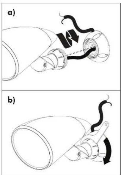
For wiring instructions see 'Speaker & Burial Cable Connections' on page 11.
WIRING & SPEAKER INSTALLATION (CONT'D)
Speaker & Burial Cable Connections
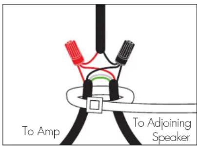
Combine and twist (clockwise) the red wires (as shown in the diagram) from the amp, speaker and to the next speaker. Secure these three wires using the provided silicone-filled wire connectors; Repeat procedure for Black wires. NOTE: You may have to cut some of the speaker cable emanating from the speaker to a more manageable size.
SPEAKER DIRECTION & SETTINGS
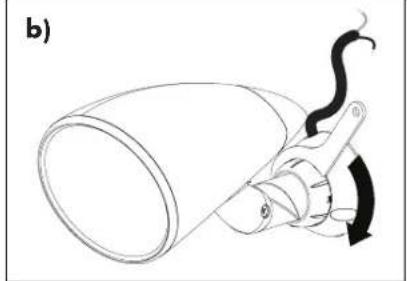
- Aim the speaker by loosening the screw in the speaker arm and retightening once the desired aim is achieved.
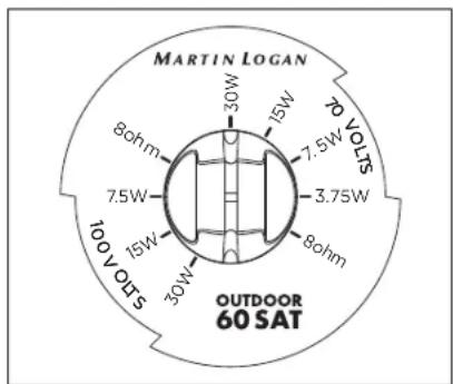
- Set the dial on every satellite speaker in your sytem. To access the dial, remove the rear cap from your satellite speaker by turning a quarter turn in a counter clockwise direction. Now pull the cap away from the satellite enclosure. Set the dial to correspond with the number of satellite speakers and subwoofers in the installation (see 'Audio Settings Chart' on page 1.5).
OPTIONAL INGROUND CONDUIT BOX
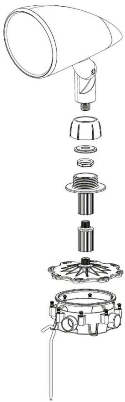
Following the same instructions outlined for the Ground Stake or Surface Mount Bracket accessory. The Outdoor Living Series Inground Conduit Box can be substituted. Knock out holes in the Inground Conduit Box as needed. Conduit is sold separately.
Included:
• (1) Inground Conduit Box
• (1) Two Piece Mounting Post
• (8) Stainless Steel Screws
• [4] Ground Stakes
Recommended Tools:
- Drill
- PVC Glue – for PVC conduit or fittings
- Silicone Caulk
- Shovel
- Hammer
• #2 Phillips Screwdriver
• Wrench
Installation Instructions

IMPORTANT! Test your system before gluing or caulking any part of the Inground Conduit Box or any conduit piping connec-
tions. Use silicone caulk to seal any openings used for cable. Allow caulk and glue to dry completely before burying the Inground Conduit Box.
OPTION 1: PVC Conduit Installation – Knock out the conduit openings to be used. Glue the conduit piping to the Inground Conduit Box.* Draw the cable through the conduit and pull at least 8 inches of cable into the box cavity.
Note: The Inground Conduit Box accepts nominal 3/4 inch Schedule 40 PVC Pipe. Other conduit pipe sizes may be used with adapters.
OPTIONAL INGROUND CONDUIT BOX
OPTION 2: Burial Cable Installation – Drill a hole into the center of the knock out slightly larger than the cable. Route the cable through and pull at least 8 inches of cable into the box cavity. Seal the entrance completely with silicone.* Place the Inground Conduit Boxes in their appropriate trench location, ensuring a minimum depth of 6 inches.
- Install the satellite speaker to the Inground Conduit Box lid, using the two piece post. Use silicone in the threads to enhance sealing of the Inground Conduit Box against moisture.*
-
Use the silicone-filled wire connectors included with the speaker to terminate the wiring connections. Turn the silicone-filled wire connectors clockwise by hand until they are tight.
-
The box may now be closed. A weatherproof gasket is attached to the cover, but for additional water intrusion protection, line the inside edge of the cover with silicone where it contacts the box, then assemble the box using the 8 screws.* Tighten the screws tightly by hand with a #2 screwdriver.
- Anchor Inground Conduit Box in the hole using the 4 provided stakes. Install all speakers and test the system before burying the boxes and wiring.
- Using a screw driver, adjust the speaker angle and position last.
*See 'IMPORTANT!' notice on the previous page.
TEST SYSTEM
After all satellites and subwoofer connections are completed, connect the wires to your receiver or amplifier.
IMPORTANT! Be sure not to let any stray'+' and'-' strands touch each other. Touching strands will cause a short circuit which could damage your amplifier.
Turn your receiver or amplifier 'On' and test the system with your favorite music. If the speakers are operating properly, refill the wire trench and enjoy your new speakers.
TO AVOID SPEAKER DAMAGE
Don't be fooled by your amplifier's volume control. It adjusts listening level—it does not indicate power output. If your speakers begin to sound harsh or grating, or if you hear the bass breaking up, turn the volume down immediately or you will damage your speakers! This type of damage constitutes abuse and is not covered by the warranty!
Tone controls and equalizers can demand even more power from an amplifier, lowering the point at which it produces clipping distortion. Use them sparingly, if at all, and do not use them when listening at loud levels.
LISTENING OUTDOORS
Outdoors there are no walls to contain sound. Background noise is louder and the distance listeners are from the speaker(s) is usually greater. Achieving a reasonable listening level can be more difficult. The tendency is to turn up the volume, however this may disturb neighbors and when turned up too high, can seriously damage the speakers or your amplifier.
The solution? In larger areas we recommend using multiple MartinLogan Outdoor Living Series speakers. Using more speakers ensures that sound is evenly distributed, allowing for reasonable listening levels at lower volumes. Demand on the amplifier is reduced and neighbors are not disturbed. Think of it this way: When lighting a large outdoor area, using multiple floodlights on a dimmer set to a low setting is far more effective than using a single floodlight with the dimmer set to high.
AUDIO SETTINGS CHART
INSTALLATION USING LONG WIRES (100 feet or longer)
| CHANNEL #1 ON AMP | CHANNEL #2 ON AMP | PRESETS ON CROWN AMP | PRESET NAME | POWER OUTPUT | SET DIAL ON SATELLITE SPEAKER | ||
| Wire Product to Channel #1 on the Crown Amplifier | Wire Product to Channel #2 on the Crown Amplifier | Select the Preset number on the Crown Amplifier specified below | Signal level provided to subwoofer / speakers | Remove the cap from the rear of the satellite speaker and position the dial to the appropriate wattage setting below | |||
| DYNAMO OUTDOOR SUB100 or DYNAMO OUTDOOR SUB120 plus OUTDOOR SAT 40 or OUTDOOR SAT 60 satellite speakers | SUB 100 SAT 40 | Preset 2 for SUB 100 and SAT 40 | 40SAT100 | 8 ohm / 70V hybrid | Number of Speakers: 1-12 | 30W (or less) | |
| SUB 100 SAT 60 | Preset 3 for SUB 100 and SAT 60 | 60SAT100 | 8 ohm / 70V hybrid | Number of Speakers: 13-24 | 1.5W (or less) | ||
| SUB 120 SAT 40 | Preset 4 for SUB 120 and SAT 40 | 40SAT120 | 8 ohm / 70V hybrid | Number of Speakers: 25-50 | 7.5W (or less) | ||
| SUB 120 SAT 60 | Preset 5 for SUB 120 and SAT 60 | 60SAT120 | 8 ohm / 70V hybrid | Number of Speakers: 50-100 | 3.8W (or less) | ||
| NO subwoofer and OUTDOOR SAT 40 or OUTDOOR SAT 60 satellite speakers | SAT 40 SAT 40 | Preset 10 for SAT 40 in Mono | 40SAT_MO NA | / 70V | Number of Speakers: 1-12 | 30W (or less) | |
| SAT 60 SAT 60 | Preset 11 for SAT 60 in Mono | 60SAT_MO NA | / 70V | Number of Speakers: 13-24 | 1.5W (or less) | ||
| SAT 40 SAT 40 | Preset 12 for SAT 40 in Stereo | 40SAT_ST NA | / 70V | Number of Speakers: 25-50 | 7.5W (or less) | ||
| SAT 60 SAT 60 | Preset 13 for SAT 60 in Stereo | 60SAT_ST NA | / 70V | Number of Speakers: 50-100 | 3.8W (or less) | ||
INSTALLATION USING SHORT WIRES (less than 100 feet) FOR 4 OR FEWER SPEAKERS
| CHANNEL #1 ON AMP | CHANNEL #2 ON AMP | PRESETS ON CROWN AMP | PRESET NAME | POWER OUTPUT | SET DIAL ON SATELLITE SPEAKER | |
| Wire Product to Channel #1 on the Crown Amplifier | Wire Product to Channel #2 on the Crown Amplifier | Select the Preset number on the Crown Amplifier specified below | Signal level provided to subwoofer / speakers | Remove the cap from the rear of the satellite speaker and position the dial to the appropriate wattage setting below | ||
| DYNAMO OUTDOOR SUB100 or DYNAMO OUTDOOR SUB120 plus 4 or less OUTDOOR SAT 40 or OUTDOOR SAT 60 satellite speakers | SUB 100 SAT 40 | Preset 6 for SUB 100 and SAT 40 | 840ST100 8 ohm / 8ohm | Bohms | ||
| SUB 100 SAT 60 | Preset 7 for SUB 100 and SAT 60 | 860ST100 8 ohm / 8ohm | ||||
| SUB 120 SAT 40 | Preset 8 for SUB 120 and SAT 40 | 840ST120 8 ohm / 8ohm | ||||
| SUB 120 SAT 60 | Preset 9 for SUB 120 and SAT 60 | 860ST120 8 ohm / 8ohm | ||||
| No Subwoofer and 4 or less OUTDOOR SAT 40 or OUTDOOR SAT 60 satellite speakers | SAT 40 SAT 40 | Preset 14 for SAT 40 in mono | 840STMO NA | / 8ohm | Bohms | |
| SAT 60 SAT 60 | Preset 15 for SAT 60 in mono | 860STMO NA | / 8ohm | |||
| SAT 40 SAT 40 | Preset 16 for SAT 40 in stereo | 840SATST NA | / 8ohm | |||
| SAT 60 SAT 60 | Preset 17 for SAT 60 in stereo | 860SATST NA | / 8ohm | |||
LIMITED WARRANTY
MartinLogan offers online warranty registration at www.martinlogan.com.
Your speaker is provided with an automatic Limited 90 Day Warranty coverage.
You have the option, at no additional charge, to receive a Limited 3 Year Warranty coverage. To obtain the Limited 3 Year Warranty coverage register your speakers at www.martinlogan.com. Save a copy of your dealer receipt as it may be requested if service is required.
MartinLogan may not honor warranty service claims unless we have a completed Warranty Registration on file at www.MartinLogan.com!
SERVICE
Should you be using your MartinLogan product in a country other than the one in which it was originally purchased, we ask that you note the following:
- The appointed MartinLogan distributor for any given country is responsible for warranty servicing only on units distributed by or through it in that country in accordance with its applicable warranty.
- Should a MartinLogan product require servicing in a country other than the one in which it was originally purchased, the end user may seek to have repairs performed by the nearest MartinLogan distributor, subject to that distributor's local servicing policies, but all cost of repairs (parts, labor, transportation) must be borne by the owner of the MartinLogan product.
- If, after owning your speakers for six months, you relocate to a country other than the one in which you purchased your speakers, your warranty may be transferable. Contact MartinLogan for details.

MARTIN LOGAN®
Lawrence, Kansas, USA tel 785.749.0133 fax 785.749.5320 www.martinlogan.com
©2023 MartinLogan Ltd. All rights reserved.
OUTDOOR | OUTDOOR 40 SAT | 60 SAT
SÉRIE OUTDOOR LIVING
par MARTIN LOGAN®
- Amplificateur Crown.
SUB 100 OU SUB120 (8 Ohm)
INSTALLATION DES CÂBLES ET DES ENCEINTES (SUITE)
INSTALLATION DES CÂBLES ET DES ENCEINTES (SUITE)
BOÎTE DE RACCORDEMENT SOUTERRAINE FACULTATIVE (SUITE)
MartinLogan offers online warranty registration at www.martinlogan.com.
- OUTDOOR LIVING SERIES
- TABLE OF CONTENTS
- OVERVIEW .... 3
- PLANNING THE INSTALL 4
- WIRING RECOMMENDATIONS .... 5
- INSTALLATION CONSIDERATIONS .... 5
- WIRING & SPEAKER INSTALLATION ..... 6
- OPTIONAL INGROUND CONDUIT BOX. 12
- TEST SYSTEM 13
- TO AVOID SPEAKER DAMAGE ..... 14
- LISTENING OUTDOORS 14
- AUDIO SETTINGS CHART .... 15
- WARRANTY 16
- SERVICE....16
- OVERVIEW
- MARTINLOGAN OUTDOOR LIVING SERIES SATELLITE SPEAKERS
- REQUIRED TOOLS
- POWER
- PLANNING THE INSTALL
- CABLE RECOMMENDATIONS
- INSTALLATION CONSIDERATIONS
- WIRING & SPEAKER INSTALLATION
- MONO SETUP USING 4 CONDUCTOR BURIAL CABLE & CROWN AMPLIFIER
- PREPARING THE 4 CONDUCTOR BURIAL CABLE
- WIRING & SPEAKER INSTALLATION (CONT'D)
- INSTALLING GROUND STAKE ACCESSORY & ATTACHING SPEAKER
- IMPORTANT
- INSTALLING SURFACE MOUNT BRACKET ACCESSORY & ATTACHING SPEAKER
- SPEAKER & BURIAL CABLE CONNECTIONS
- SPEAKER DIRECTION & SETTINGS
- OPTIONAL INGROUND CONDUIT BOX
- INCLUDED
- RECOMMENDED TOOLS
- INSTALLATION INSTRUCTIONS
- TEST SYSTEM
- TO AVOID SPEAKER DAMAGE
- LISTENING OUTDOORS
- AUDIO SETTINGS CHART
- LIMITED WARRANTY
- MARTINLOGAN OFFERS ONLINE WARRANTY REGISTRATION AT WWW.MARTINLOGAN.COM
- SERVICE
- MARTIN LOGAN®
- OUTDOOR | OUTDOOR 40 SAT | 60 SAT
- SÉRIE OUTDOOR LIVING
- INSTALLATION DES CÂBLES ET DES ENCEINTES (SUITE)
- BOÎTE DE RACCORDEMENT SOUTERRAINE FACULTATIVE (SUITE)
Brand : Martin Logan
Model : Outdoor 40 Sat
Category : Speaker