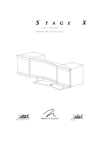
Stage X - Speaker Martin Logan - Free user manual and instructions
Find the device manual for free Stage X Martin Logan in PDF.


User questions about Stage X Martin Logan
0 question about this device. Answer the ones you know or ask your own.
Ask a new question about this device
Download the instructions for your Speaker in PDF format for free! Find your manual Stage X - Martin Logan and take your electronic device back in hand. On this page are published all the documents necessary for the use of your device. Stage X by Martin Logan.
USER MANUAL Stage X Martin Logan
natural_image
Technical line drawing of a mechanical bracket assembly (no text or symbols)
text_image
Warning symbol with exclamation mark inside triangle, commonly used to indicate a hazard or alert.1 Read these instructions.
2 Keep these instructions.
3 Heed all warnings.
4 Follow all instructions.
5 Do not use this apparatus near water.
6 Clean only with dry cloth.
7 Do not block any ventilation openings. Install in accordance with the manufacturer's instructions.
8 Do not install near any heat sources such as radiators, heat registers, stoves, or other apparatus (including amplifiers) that produce heat.
9 Do not defeat the safety purpose of the polarized or grounding-type plug. A polarized plug has two blades with one wider than the other. A grounding type plug has two blades and a third grounding prong. The wide blade or the third prong are provided for your safety. If the provided plug does not fit into your outlet, consult an electrician for replacement of the obsolete outlet.
10 Protect the power cord from being walked on or pinched particularly at plugs, convenience receptacles, and the point where they exit the apparatus.
11 Only use attachments/accessories specified by the manufacturer.
12 Use only with the stand, tripod, bracket, or table specified by the manufacturer, or sold with the apparatus.
13 Unplug this apparatus during lightning storms or when unused for long periods of time.

14 Refer all servicing to qualified service personnel. Servicing is required when the apparatus has been damaged in any way, such as power-cord or plug is damaged, liquid has been spilled or objects have fallen into the apparatus, the apparatus has been exposed to rain or moisture, does not operate normally, or has been dropped.
15 The mains plug of the power supply cord shall remain readily operable.
16 To completely disconnect this equipment from the mains, disconnect the power supply cord plug from the receptacle.
17 WARNING! To reduce the risk of fire or electric shock, this apparatus should not be exposed to rain or moisture and objects filed with liquids, such as vases, should not be placed on this apparatus.

WARNING
SHOCK HAZARD DO NOT OPEN
AVIS: RISQUE DE CHOC ELECTRIQUE NE PAS OUVRIR
CAUTION!
- To reduce risk of electric shock, do no remove cover (or back).
• No user serviceable parts inside.
• Refer servicing to qualified service personnel.
Service Information
For service this product should be returned to your authorized distributor. In the US, please visit www.martinlogan.com for contact information. Outside the US, please use the distributor locator at www.martinlogan.com.
NOTE: This equipment has been tested and found to comply with the limits for a Class B digital device, pursuant to part 15 of the FCC Rules. These limits are designed to provide reasonable protection against harmful interference in a residential installation. This equipment generates uses and can radiate radio frequency energy and, if not installed and used in accordance with the instructions, may cause harmful interference to radio communications. However, there is no guarantee that interference will not occur in a particular installation. If this equipment does cause harmful interference to radio or television reception, which can be determined by turning the equipment off and on, the user is encouraged to try to correct the interference by one or more of the following measures:
— Reorient or relocate the receiving antenna.
— Increase the separation between the equipment and receiver.
— Connect the equipment into an outlet on a circuit different from that to which the receiver is connected.
— Consult the dealer or an experienced radio/TV technician for help.
Thank you—to you the MartinLogan owner, for loving what we do, and for making it possible for us to do what we love.
natural_image
Technical line drawing of a mechanical component with a coiled cable and a 1/8-inch base (no text or symbols on the diagram itself)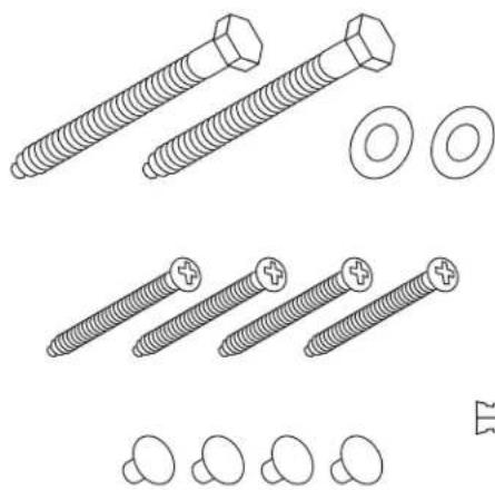
natural_image
Technical line drawings of various screw and nut components (no text or labels)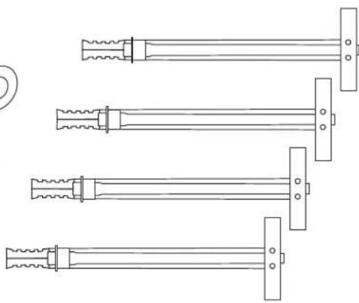
natural_image
Technical line drawing of four mechanical components with threaded ends and mounting brackets (no text or symbols)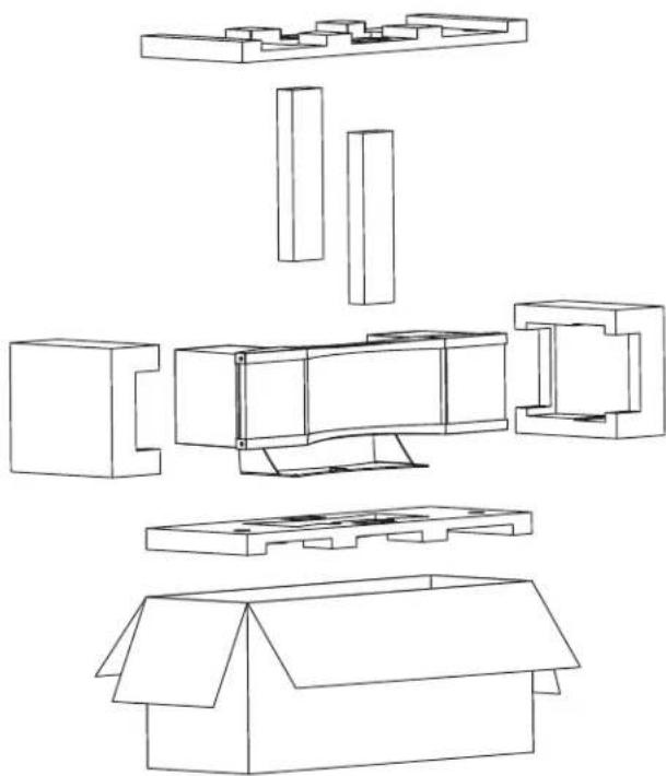
natural_image
Exploded view diagram of a mechanical assembly showing internal components and housing (no text or labels)Serial Numbers:
Record your serial number here for easy reference. You will need this information when filling out your warranty registration. Stage X's serial number is located near the bottom of the backplate and on the shipping container. Each individual unit has a unique serial number.
Numéros de série :
text_image
Warning symbol with exclamation mark inside triangle, commonly used to indicate a hazard or alert.
In accordance with the European Union WEEE (Waste Electrical and Electronic Equipment) directive effective August 13, 2005, we would like to notify you that this product may contain regulated materials which upon disposal, according to the WEEE directive, require special reuse and recycling processing.
For this reason MartinLogan has arranged with our distributors in European Union member nations to collect and recycle this product at no cost to you. To find your local distributor please contact the dealer from whom you purchased this product, email info@martinlogan.com or visit the distributor locator at www.martinlogan.com.
Please note, only this product itself falls under the WEEE directive. When disposing of packaging and other related shipping materials we encourage you to recycle these items through the normal channels.

The exclamation point within an equilateral triangle is intended to alert the user to the presence of important operating and maintenance (servicing) instructions in the literature accompanying the appliance.

The lightning bolt flash with arrowhead symbol, within an equilateral triangle, is intended to alert the user to the presence of uninsulated "dangerous voltage" within the product's enclosure that may be of sufficient magnitude to constitute a risk of electric shock.

WARNING! Do not use your Stage X loudspeakers outside of the country of original sale—voltage requirements vary by country. Improper voltage can cause damage that will be potentially expensive to repair. The Stage X is shipped to authorized MartinLogan distributors with the correct power supply for use in the country of intended sale. A list of authorized distributors can be accessed at www.martinlogan.com or by emailing info@martinlogan.com.

Tested to Comply with FCC Standards FOR HOME OR OFFICE USE

Stage X
This device complies with part 15 of the FCC Rules. Operation is subject to the following two conditions: (1) This device may not cause harmful interference, and (2) this device must accept any interference received, including interference that may cause undesired operation.
Safety Warnings and Installation in Brief (English)

WARNING/CAUTION!
- Hazardous voltages exist inside—do not remove cover.
• Refer servicing to a qualified technician. - To prevent fire or shock hazard, do not expose this module to moisture.
- Turn amplifier off and unplug speaker should any abnormal conditions occur.
- Turn amplifier off before making or breaking any signal connections!
- Do not operate if there is any visual damage to the electrostatic panel element.
- Do not drive speaker beyond its rated power.
- The power cord should not be installed, removed, or left detached from the speaker while the other end is connected to an AC power source.
- No candles or other sources of open flame should be placed on the speaker.
- No liquids either in glasses or vases should be placed on speaker.
- Speaker should not be exposed to dripping or splashing liquids.
- The terminals marked with the lightning bolt symbol should be connected by an instructed person or by way of ready made terminals.
- The power cord should remain readily operable should any abnormal conditions occur.
We know you are eager to hear your new MartinLogan loudspeakers, so this section is provided to allow fast and easy set up. Once you have them operational, please take the time to read, in depth, the rest of the information in the enclosed manual. It will give you perspective on how to attain the greatest possible performance from this most exacting transducer.
If you should experience any difficulties in the setup or operation of your MartinLogan speakers, please refer to the Room Acoustics, Placement or Operation sections of the enclosed owner's manual. Should you encounter a persistent problem that cannot be resolved, please contact your authorized MartinLogan dealer. They will provide you with the appropriate technical analysis to alleviate the situation.
Step 1: Unpacking
Remove your new MartinLogan speakers from their packing.
Step 2: Placement
Place speakers at least two feet from any wall and angle them slightly toward your listening area. This is a good place to start. Please see the Placement section of the enclosed manual for more details.
Step 3: Power Connection (AC) (see warning)
MartinLogan speakers require AC power to energize their electrostatic cells. Using the AC power cords provided, plug them in first to the AC power receptacle on the rear panel of the speaker, making sure that you have made a firm connection, and then to the wall outlet. Please see the Operations section of the enclosed manual for more details.
Step 4: Signal Connection
Use the best speaker cables you can. Higher quality cable, available from your specialty dealer, is recommended and will give you superior performance. Spade connectors are suggested for optimum contact and ease of installation.
Attach your speaker cables to the Signal Input section on the rear panel. Be consistent when connecting speaker leads to the terminals on the back of the speaker: take great care to assign the same color to the (+) terminal on both the left and right channels. If bass is nonexistent and you cannot discern a tight, coherent image, you may need to reverse the (+) and (−) leads on one side to bring the system into proper polarity.
If your speaker is equipped for Bi-wiring/Passive Bi-amping, turn to the Operations section of the enclosed manual for proper setup of your MartinLogan speakers.
Step 5: Listen and Enjoy
natural_image
Warning symbol with exclamation mark inside triangle (no text or numbers)
text_image
Warning symbol with exclamation mark inside triangle, commonly used to indicate a hazard or cautionStep 3: Power Connection (AC) (see warning)
text_image
Warning symbol with exclamation mark inside triangle, commonly used to indicate a hazard or cautionnatural_image
Warning symbol with exclamation mark inside triangle (no text or numbers)ΟΤΟΥ

text_image
Warning symbol with exclamation mark inside triangle, commonly used to indicate a hazard or alert.natural_image
Warning symbol with exclamation mark inside triangle (no text or numbers)
text_image
Warning symbol with exclamation mark inside triangle, commonly used to indicate a hazard or alert.natural_image
Warning symbol with exclamation mark inside triangle (no text or numbers)
text_image
Warning symbol with exclamation mark inside triangle, commonly used to indicate a hazard or alert.text_image
1/8-inch (1/8 po) CE
natural_image
Technical line drawing of a mechanical component with no visible text or symbols69Hz-22kHz ± 3dB
39 lbs. (17.7kg)
4 Ohms
90dB @ 2.83 V/M
text_image
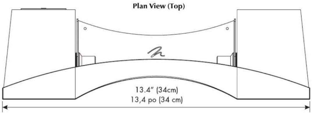
13.4" (34cm) 13,4 po (34 cm)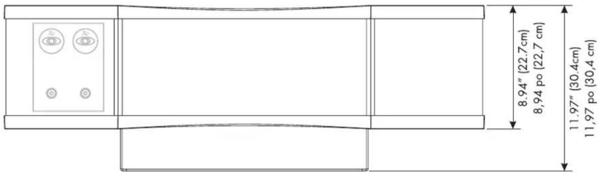
text_image
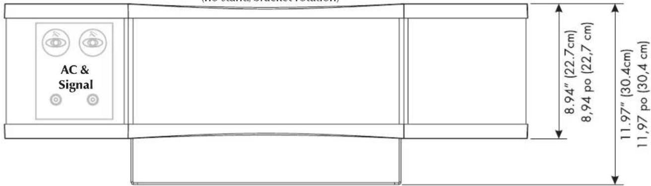
8.94" (22.7 cm) 8,94 po (22,7 cm) 11.97" (30.4 cm) 11,97 po (30,4 cm)
text_image
10.26" (26.1cm) 10,26 po (26,1 cm)
text_image
13.4" (34cm) 13,4 po (34 cm) 14.6" (37.1cm) 14,6 po (37,1 cm)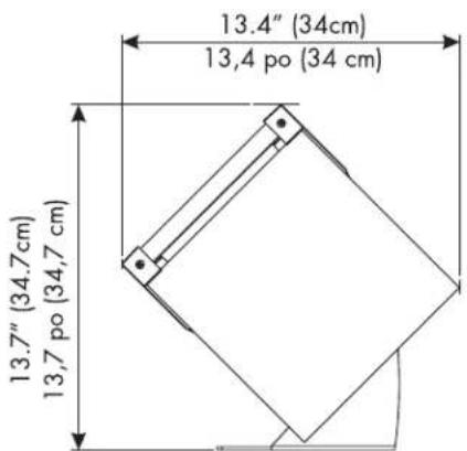
text_image
13.4" (34cm) 13,4 po (34 cm) 13.7" (34.7cm) 13,7 po (34,7 cm)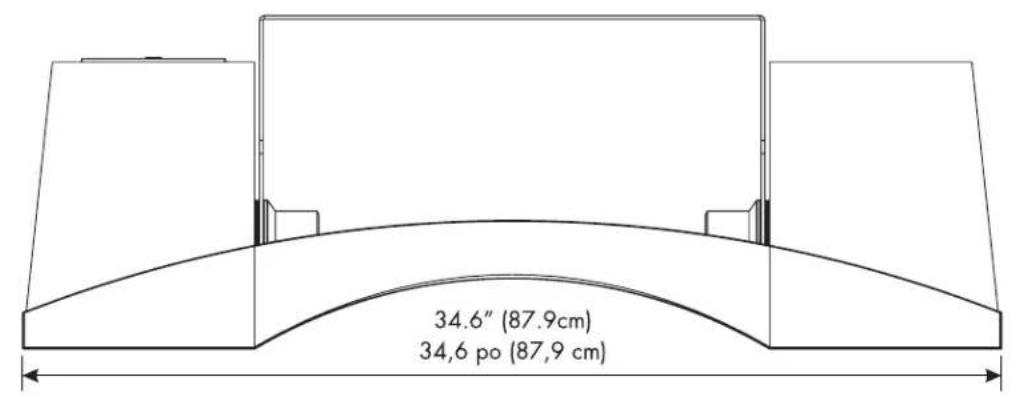
text_image
34.6" (87.9cm) 34,6 po (87,9 cm)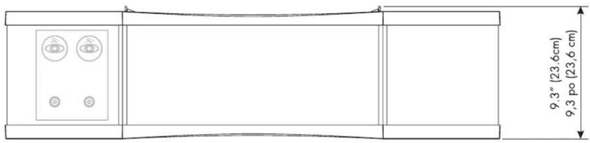
text_image
9.3" (23.6cm) 9,3 po (23,6 cm)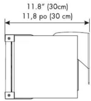
text_image
11.8" (30cm) 11,8 po (30 cm)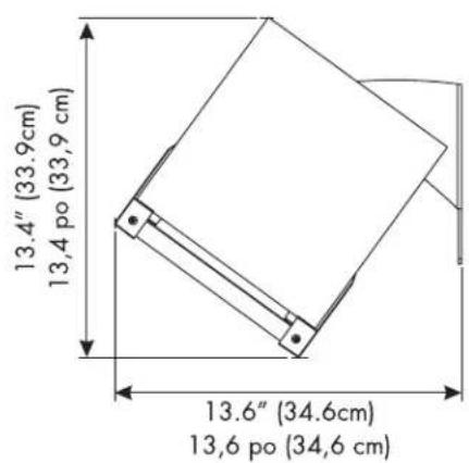
text_image
13.4" (33.9cm) 13,4 po (33,9 cm) 13.6" (34.6cm) 13,6 po (34,6 cm)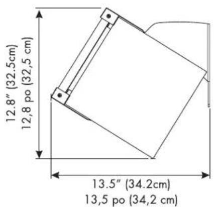
text_image
12.8" (32.5cm) 12,8 po (32,5 cm) 13.5" (34.2cm) 13,5 po (34,2 cm)
natural_image
Technical line drawing of a mechanical housing or bracket (no text or symbols)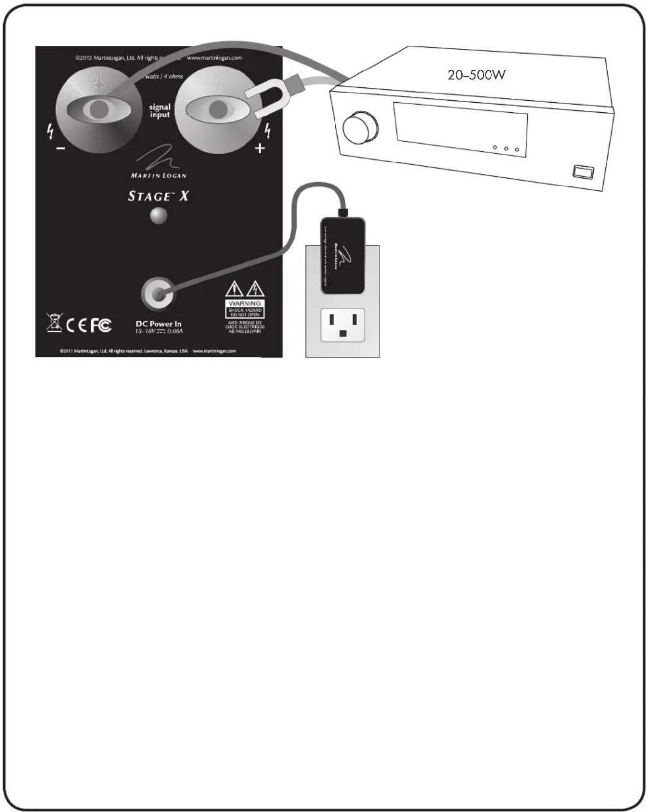
text_image
©2012 MartinLogan, Ltd. All rights reserved. www.martinlogan.com watts / 4 ohms signal input MARTIN LOGAN STAGE™ X CE FC DC Power In 15-18V === 0.08A WARNING EQUATORIO DO NOT OPEN AVE: RISQUE DE CHIC ELECTRONIC NE PAS QUARTER ©2017 MartinLogan, Ltd. All rights reserved. Lawrence, Kansas, USA www.martinlogan.com 20-500WContents Introduction
Contents 19
Introduction....19
Connections 20
AC Power Connection....20
Signal Connection 20
Break-In....20
Installation 21
Using the Adjustable Mount 21
Installation Options 21
Rubber Bumper Feet 21
Mounting the Stage X on a Wall 22
Home Theater....25
Electrostatic Advantages 26
MartinLogan Exclusives....27
XStat™ Transducer....27
CLS ^™ (Curvilinear Line Source)....27
Generation 2 Diaphragm. 27
MicroPerf Stator....27
Vacuum Bonding....27
Folded Motion™ Tweeter 27
Electrostatic History.... 28
Frequently Asked Questions and Troubleshooting ..... 30
Frequently Asked Questions 30
Troubleshooting....31
General Information 32
Specifications.... 32
Warranty and Registration.... 32
Serial Number 32
Service 32
Dimensional Drawings ...... 33
On Stand 33
Wall Mounting....34
Glossary of Audio Terms 35
Congratulations! You have invested in one of the world's premier loudspeaker systems.
The Stage X represents an advanced combination of sonic technologies establishing an unprecedented direction for audiophile design. The result of years of research, the new Stage X hybrid electrostatic loudspeaker features XStat ^™ technology establishing new standards for efficiency, dynamics and precision in a loudspeaker.
Stage X's CLS XStat™ transducer builds upon the legacy of MartinLogan's electrostatic heritage with the incorporation of advanced vacuum bonding and MicroPerf stat panels, providing even greater efficiency and precision.
Through rigorous testing, the curvilinear electrostatic panel has proven itself to be one of the most durable and reliable transducers available today. Fabricated from a custom tool punched high-grade steel, the patented panel is then coated with a special polymer that is applied via a proprietary electrostatic bonding process. This panel assembly houses a membrane just 0.0005 of an inch thick. Ruggedly constructed and insulated, the panel is rated to easily handle up to 250 watts of continuous power with no deleterious effects.
Featuring an advanced crossover topology derived from the Summit loudspeaker, MartinLogan engineered the Stage X crossover using precision audiophile-grade polypropylene capacitors and high-purity air-core coils. This advanced crossover topology flawlessly preserves sonic subtleties while effortlessly handling the broadest range of dynamics.
The materials in your new Stage X speaker are of the highest quality and will provide years of enduring enjoyment and deepening respect. The cabinetry is constructed from dense composite material for acoustical integrity and features hand rubbed wood veneers.
The other sections of your User's Manual explain in detail the operation of your Stage X speaker and the philosophy applied to their design. A clear understanding of your speaker will insure that you obtain maximum performance and pleasure from this most exacting transducer. It has been designed and constructed to give you years of trouble-free listening enjoyment.
AC Power Connection
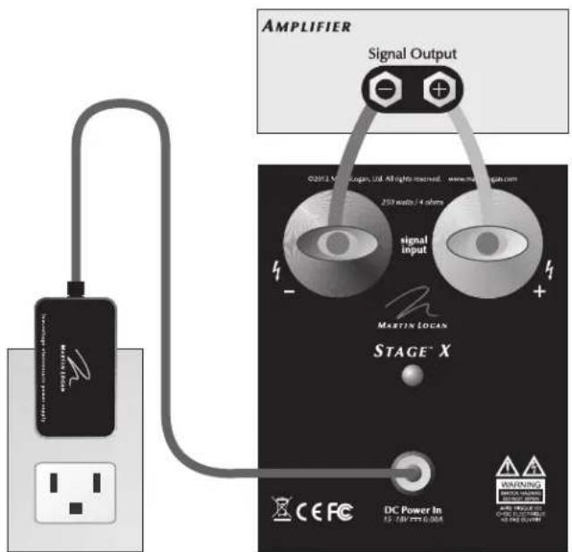
Your Stage X uses an external low-voltage power supply to energize its electrostatic panel. For this reason the proper low-voltage power supply is provided. The power supply should be firmly inserted into the 'Power In' receptacle on the rear connection panel of the speaker, then to any convenient AC wall outlet (see figure 1). Your Stage X integrates a signal sensing circuit which will switch the Stage X off after a few minutes of no music signal, and requires less than two seconds to recharge the panel when a music signal is present.
Your Stage X speaker is provided with a power supply for the power service supplied in the country of original consumer sale. The AC power rating applicable to a particular unit is specified both on the packing carton and on the power supply.
If you remove your Stage X speakers from the country of original sale, be certain that the AC power supplied in any subsequent location is suitable before connecting the low-voltage power supply. Substantially impaired performance or severe damage may occur to a Stage X speaker if operation is attempted from an incorrect AC power source.

WARNING! The power supply should not be installed, removed, or left detached from the speaker while connected to an AC power source.
text_image
AMPLIFIER Signal Output O2613 Nanogene, Ltd. All rights reserved. www.nangene.com signal input 250 amps / 4 ohms MARTIN-LOGAN STAGE™ X CE FC DC Power In WINNING MINING WARNING MINING INSURANCE MINING INSURANCE MINING INSURANCE MINING INSURANCEFigure 1. Power and signal connection.
Signal Connection
Use the best speaker cables you can. The length and type of speaker cable used in your system will have an audible effect. Under no circumstance should a wire of gauge higher (thinner) than #16 be used. In general, the longer the length used, the greater the necessity of a lower gauge, and the lower the gauge, the better the sound, with diminishing returns setting in around #8 to #12.
A variety of speaker cables are now available whose manufacturers claim better performance than standard heavy gauge wire. We have verified this in many cases, and the improvements available are often more noticeable than the differences between wires of different gauge. The effects of cables may be masked if the equipment is not of the highest quality.
Connections are made at the signal input section on the rear electronics panel of the Stage X (see figure 1). Use spade connectors for optimum contact. Make certain that all of your connections are tight. Be consistent when connecting speaker leads to the terminals on the back of the Stage X. Take great care to assign the same color to the (+) terminal on both the speaker and the amplifier.

WARNING! Turn your amplifier off before making or breaking any signal connections!
Break-In
When you first begin to play your Stage X speaker, it will sound a bit bass shy. This is due to the high-quality, long-life components used in our woofer. Our custom made, butyl surround woofer requires at least 80 hours of break-in at 90 dB (moderate listening levels) before any critical listening. The break-in requirements of the crossover components (and, to a lesser degree, the electrostatic transducer) are equal.
Using the Adjustable Mount
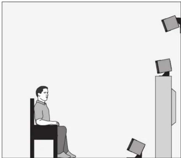
For optimum performance the Stage X must be tilted on its stand towards the main listening position and directed towards the audience's ears (see figure 3). After you have placed your Stage X in its final location, loosen the 2 knobs located on the stand arm, pivot the Stage X towards the main listening position, and then re-tighten the knobs.

The stand shipped with the Stage X loudspeaker is designed for use only with the Stage X. Use with other appliances may result in instability causing possible injury.
Installation Options
On the Television
If your television provides a wide, level and stable platform, the shielded Stage X can be placed directly on top of the television (see figure 3). For this option we recommend installation of the rubber bumper feet.
On the Wall
The adjustable mount (stand) allows you to mount the Stage X on the wall (see figures 2 and "Mounting the Stage X On A Wall,"). If hanging the Stage X on the wall is the best placement for your system, the adjustable mount (stand) will allow you to tilt the Stage X towards the listening position.
natural_image
Illustration of a person sitting in a chair facing a TV with multiple monitors, no text or symbols presentFigure 2. Stage X installation on the floor, on a television and on a wall.
On the Floor
Placing the Stage X on the floor might position it too low to blend with the front speakers. (see figure 3). If placing the Stage X on the floor is the best placement for your system, the adjustable mount (stand) will allow you to tilt the Stage X towards the listening position. For this option we recommend installation of the rubber bumper feet.

WARNING! Installation other than that described in the body of this document requires specific documentation from MartinLogan.
Rubber Bumper Feet
If you are using the Stage X on top of your television, or setting it on any type of surface, we recommend installing the 4 rubber bumper feet included with the Stage X. The Stage X ships with these 4 rubber bumper feet installed. The following instructions describe how to install the feet if they have been previously removed for another installation.
Rubber Bumper Feet Installation Instructions:
-
Prepare a surface to work on by laying down a towel or large soft cloth on top of a large flat surface.
-
Securely tighten the 2 knobs on the Stage X stand, making sure the Stage X cabinet is level with the stand.
-
Turn the Stage X upside down so that the bottom of the stand is pointing up.
-
Insert the 4 rubber bumper feet in the 4 holes on the bottom of the stand.
Mounting the Stage X On A Wall
NOTE: These instructions describe how to remove the stand from the Stage X and mount it to the wall. MartinLogan recommends using 4 wall anchors and machine screws to secure the Stage X bracket to the wall. When drilling pilot holes for the wall bracket, if any screw location hits a stud, it is recommended to directly screw a lag screw into the stud.
Required hardware (included):
(4) TOGGLER ^® SNAPTOGGLE ^® Toggle Bolts (Wall Anchors)
(4) 10-24 x 1.25" machine screws
(1) 1/8" Allen Tool
(2) 1/4" x 2.5" Lag Screws (7/16" head)
(2) Flat Washers for Lag Screws
Required tools (not supplied):
2 ft. level or a 2 ft. board and a small level
Electric drill
1/8" drill bit
1/2" drill bit
7/16" socket drive
Phillips screwdriver
Pencil
NOTE: These instructions assume the mounting surface is of wood frame and standard sheetrock construction. If you wish to mount the Stage X to another type of material or construction, you should Stage X a bonded contractor.

WARNING! This operation requires 2 people. Do not attempt to install your Stage X by yourself
WARNING! For safety reasons, the Stage X is shipped with four small rubber feet installed on the bottom of the metal stand. If the stand is being mounted on a wall, these small rubber feet must be removed.

natural_image
Technical line drawing of a mechanical assembly with directional arrows indicating motion (no text or symbols)Figure 3. Remove the stand from the speaker.
1 Prepare a flat surface with padding and sheets to protect the speaker as you work on it. Disconnect any wires and carefully place the Stage X on the work surface. Loosen the two large knobs securing the stand. Rotate the stand back and up allowing the speaker itself to sit directly on the surface.
2 Make sure that the 4 small rubber feet on the bottom of the Stage X's metal bracket/stand are removed. If they are not, do so at this time by gently pulling and rocking them out of the holes.
3 Remove the stand/wall-bracket by completely unscrewing the two large knobs (figure 3).

IMPORTANT! Make sure that the four press fit washers remain in place, two attached to the bracket and two attached to the speaker cabinet.
natural_image
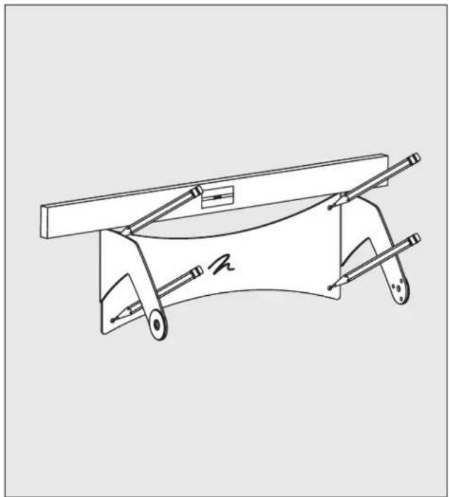
Technical line drawing of a mechanical clamp or bracket assembly (no text or symbols)Figure 4. Level the stand at the mounting location and mark the holes.
4 Place the bracket against the wall at the desired location. It is important that the entire area behind the bracket, and 8.5 inches to the left and right of the bracket be free from obstructions and completely flat.

IMPORTANT! To allow the Stage X to fully rotate up or down, the following area must be free of obstructions:
— 4 inches above of the bracket
— 6 inches below of the bracket
— 8.5 inches left and right of the bracket
5 Using a level, square the bracket and mark the 4 hole locations.
natural_image
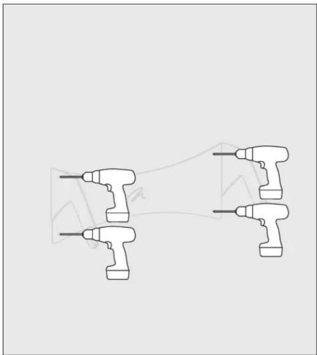
Four identical electric drill motors arranged in a row, no text or symbols visibleFigure 5. Drill pilot holes at the marked locations. Widen any non-stud holes.
6 Using a 1/8" bit, drill four pilot holes.

IMPORTANT! If you drill into a stud during this step, DO NOT widen the hole and DO NOT install a toggle bolt wall anchor at this location—you will eventually be installing a lag screw directly into the stud.
7 Use a 1/2" drill bit, widen the pilot holes so toggle bolt wall anchors can be installed.
text_image
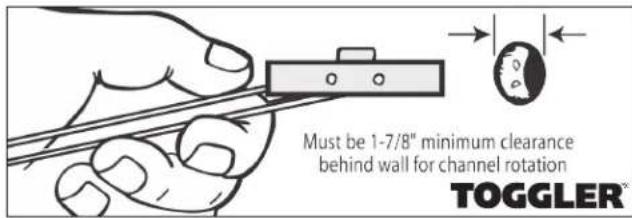
Must be 1-7/8" minimum clearance behind wall for channel rotation TOGGLER®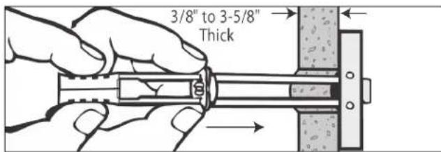
text_image
3/8" to 3-5/8" Thick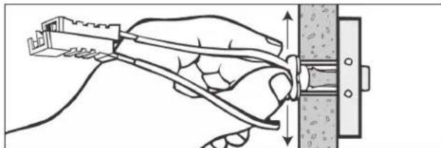
natural_image
Illustration of a hand using a tool to tighten a bolted joint with a mechanical bracket (no text or symbols)Figure 6. Installing a toggle bolt wall anchor.
8 Install TOGGLER ^ SNAPTOGGLE ^ toggle bolts at all locations with a 1/2-inch hole. To do this:
A) Hold the toggle bolt metal channel flat alongside the plastic straps. Slide the metal channel through the 1/2-inch hole.
B) Hold the ends of the straps between thumb and forefinger and even them out. Pull the entire toggle bolt toward you until the channel rests flush behind the wall. Slide the plastic cap along the straps with the other hand until the flange of the cap is flush with the wall.
C) Place a thumb between the straps at the wall. Push the thumb side to side, snapping off the straps level with the flange.
U.S. Patent No. 6,161,999 and foreign counterparts thereof and of U.S. Patent No. 4,650,368. TOCGLER and its type-face and SNAPTOGGLE are worldwide registered trademarks of Mechanical Plastics Corp. For further technical information on these anchors, visit www.toggler.com/products_hwh.html.
natural_image
Pure mechanical part diagram without any text, numbers, or symbols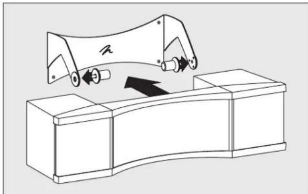
natural_image
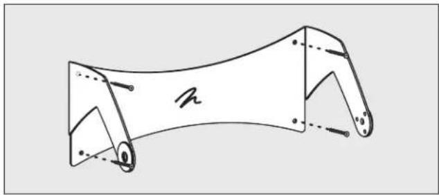
Technical line drawing of a mechanical assembly with no visible text or symbolsFigure 7-8. Attach the stand to the wall using 4 screws. Install the Stage X.
9 Hold the bracket at the mounting location.
Install the 10-24 x 1.25-inch machine screws in any locations where toggle bolt wall anchors were placed.
Install a lag screw and washer at any location where a stud was found.
10 With the help of an assistant, line up the Stage X speaker with the mounted bracket and attach it using the two large knobs.

IMPORTANT! There should be four press fit washers—two attached to the bracket and two attached to the speaker cabinet. When correctly installed these washers should be flush next to each other between the bracket and speaker cabinet.
It had long been the practice of stereo buffs to connect their television to a stereo system. The advantage was the use of the larger speakers and more powerful amplifier of the stereo system. Even though the sound was greatly improved, it was still mono and limited by the broadcast signal.
In the late 1970's and early 1980's two new home movie formats became widely available to the public: VCR and laser disc.
By 1985, both formats had developed into very high quality audio/video sources. In fact, the sonic performance of some video formats exceeded audio-only formats. Now, with theater-quality sound available at home, the only element missing was the “surround sound” presentation found in movie houses.
Fortunately, Dolby and DTS encoded movies (including almost all films) have the same surround sound information encoded on home releases as the theatrical release. All that is required to retrieve this information is a decoder and additional speakers and amps to reproduce it.
Home theater is a complex purchase and we recommend that you consult your local MartinLogan dealer, as they are well versed in this subject.
natural_image
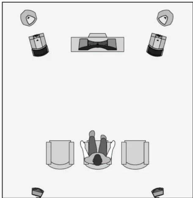
Top-down diagram of a person reclining in a chair with multiple camera and monitor cases arranged around (no text or symbols)Figure 9. Stage X as the center channel speaker.
Each piece of a surround system can be purchased separately. Take your time and buy quality. No one has ever complained that the movie was too real. The following list and descriptions will give you only a brief outline of the responsibilities and demands placed on each speaker.
Front Left and Front Right
If these speakers will be the same two used for your stereo play-back, they should be of very high quality and able to play loudly (over 102 dB) and reproduce bass below 80 Hz.
Center Channel
This is the most important speaker in a home theater system, as almost all of the dialogue and a large portion of the front speaker information is reproduced by the center channel. It is important that the center speaker be extremely accurate and mate well the front speakers, and that it is recommended for use as a center speaker. This is not the place to cut corners.
Surround Speakers
We recommend (along with the film industry) that the surround speakers play down to at least 80 Hz. Surround speakers contain the information that makes it appear that planes are flying over your head. Some may suggest that this is the place to save money and purchase a small, inexpensive speaker. If you choose to do so, be prepared to upgrade in the future as discrete multi-channel digital encoding is proliferating rapidly and the demands on surround speakers have increased.
Subwoofer
With any good surround system you will need one or more high-quality subwoofers (the .1 in a 5.1 channel surround system). Most movie soundtracks contain large amounts of bass information as part of the special effects. Good subwoofers will provide a foundation for the rest of the system.
How can sound be reproduced by something that you are able to see through? Electrostatic energy makes this possible.
Where the world of traditional loudspeaker technology deals with cones, domes, diaphragms and ribbons that are moved with magnetism, the world of electrostatic loudspeakers deals with charged electrons attracting and repelling each other.
To fully understand the electrostatic concept, some background information will be helpful. Remember when you learned in a science or physics class that like charges repel each other and opposite charges attract each other? Well, this principle is the foundation of the electrostatic concept.
An electrostatic transducer consists of three pieces: stators, the diaphragm and spacers (see figure 10). The diaphragm is what actually moves to excite the air and create music. The stator's job is to remain stationary, hence the word stator, and to provide a reference point for the moving diaphragm. The spacers provide the diaphragm with a fixed distance in which to move between the stators.
As your amplifier sends music signals to an electrostatic speaker, these signals are changed into two high-voltage signals that are equal in strength but opposite in polarity. These high voltage signals are then applied to the stators. The resulting electrostatic field, created by the opposing high voltage on the stators, works simultaneously with and against the diaphragm, consequently moving it back and forth, producing music. This technique is known as

text_image
MicroPerf Stator ClearSpar Spacers Plasma Bonded DiaphragmFigure 10. Cut away view of an XStat ^™ electrostatic transducer. Notice the simplicity due to minimal parts usage.
push-pull operation and is a major contributor to the sonic purity of the electrostatic concept due to its exceptional linearity and low distortion.
Since the diaphragm of an electrostatic speaker is uniformly driven over its entire area, it can be extremely light and flexible. This allows it to be very responsive to transients, thus perfectly tracing the music signal. As a result, great delicacy, nuance and clarity is possible. When you look at the problems of traditional electromagnetic drivers, you can easily see why this is so beneficial. The cones and domes which are used in traditional electromagnetic drivers cannot be driven uniformly because of their design. Cones are driven only at the apex. Domes are driven at their perimeter. As a result, the rest of the cone or dome is just “along for the ride”. The very concept of these drivers requires that the cone or dome be perfectly rigid, damped and massless. Unfortunately, these conditions are not available in our world today.
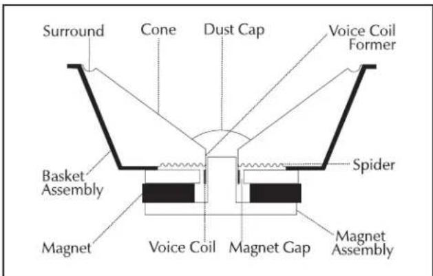
To make these cones and domes move, all electromagnetic drivers must use voice coils wound on formers, spider assemblies, and surrounds to keep the cone or dome in position (see figure 11). These pieces, when combined with the high mass of the cone or dome materials used, make it an extremely complex unit with many weaknesses and potential for failure. These faults contribute to the high distortion products found in these drivers and is a tremendous disadvantage when you are trying to change motion as quickly and as accurately as a loudspeaker must (40,000 times per second!).
text_image
Surround Cone Dust Cap Voice Coil Former Basket Assembly Spider Magnet Voice Coil Magnet Gap Magnet AssemblyFigure 11. Cut away view of a typical moving coil driver. Notice the complexity due to the high number of parts.
XStat™ Transducer
XStat ^™ transducers incorporate a myriad of technology and design innovations including CLS ^™ , MicroPerf, Generation 2 Diaphragms, ClearSpars ^™ , and Vacuum Bonding.
CLS™ (Curvilinear Line Source)
Since the beginning of audio, achieving smooth dispersion has been a problem for all designers. Large panel transducers present unique challenge because the larger the panel, the more directional the dispersion pattern becomes.
Wide range electrostats have long been one of the most problematic transducers because they attain their full range capabilities via a large surface area. It looked as if they were in direct conflict to smooth dispersion and almost every attempt to correct this resulted in either poor dispersion or a serious compromise in sound quality.
After extensive research, MartinLogan engineers discovered an elegantly simple solution to achieve a smooth pattern of dispersion without degrading sound quality. By curving the horizontal plane of the electrostatic transducer, a controlled horizontal dispersion pattern could be achieved, yet the purity of the almost massless electrostatic diaphragm remained uncompromised. After creating this technology, MartinLogan developed the production capability to bring it out of the laboratory and into the market place. You will find this proprietary MartinLogan technology used in all of our electrostatic products. It is one of the many reasons behind our reputation for high quality sound with practical usability. This is also why you see the unique “see through” cylindrical shape of MartinLogan products.
Generation 2 Diaphragm
Stage X's diaphragm employs an extremely sophisticated conductive coating applied to the polymer surface at an atomic level using a plasma bonding process. A proprietary compound is driven into the surface of the polymer film in an oxygen free argon chamber. This process allows extremely uniform surface resistivity characteristics, an optically transparent surface, and a nearly massless diaphragm. This uniform surface resistivity controls the electrostatic charge on the diaphragm surface and regulates its migration. As a result, no discharging or "arcing" can occur.
MicroPerf Stator
Sleek. Compact. MicroPerf stator technology, featured in all XStat™ transducers, reveals more open playable area in each panel, offering increased performance from even more compact stat panels. It is significant to note that the XStat™ transducer in the radical new Stage X loudspeaker supports the bandwidth and dynamics associated with traditional electrostatic panels nearly twice its size.
Vacuum Bonding
To achieve the power, precision, and strength of the XStat ^™ transducer, two insulated high-purity carbon steel stators along with a proprietary plasma bonded diaphragm and ClearSpar ^™ spacers are fused into a curved geometry with an aerospace adhesive whose strength exceeds that of welding. Our proprietary Vacuum Bonding process guarantees uniform diaphragm tensioning and extremely precise construction tolerances, resulting in unequivocal precision, linearity and efficiency.
Folded Motion™ Tweeter
The Folded Motion Tweeter works by moving air (which creates sound) perpendicular to the folded ridges of the diaphragm, similar to how an accordion works. This extremely low mass diaphragm "squeezes" air and requires almost 90% less excursion than the typical 1" dome tweeter, which drastically minimizes distortion while providing a lightning fast response time. The increased surface area also provides a wide, yet controlled sound dispersion to create a realistic and carefully etched sound stage.
In the late 1800's, any loudspeaker was considered exotic. Today, most of us take the wonders of sound reproduction for granted.
It was 1880 before Thomas Edison had invented the first phonograph. This was a horn-loaded diaphragm that was excited by a playback stylus. In 1898, Sir Oliver Lodge invented a cone loudspeaker, which he referred to as a "bellowing telephone", that was very similar to the conventional cone loudspeaker drivers that we know today. However, Lodge had no intention for his device to reproduce music because in 1898 there was no way to amplify an electrical signal! As a result, his speaker had nothing to offer over the acoustical gramophones of the period. It was not until 1906 that Dr. Lee DeForrest invented the triode vacuum tube. Before this, an electrical signal could not be amplified. The loudspeaker, as we know it today, should have ensued then, but it did not.
Amazingly, it was almost twenty years before this would occur.
In 1921, the electrically cut phonograph record became a reality. This method of recording was far superior to the mechanically cut record and possessed almost 30dB of dynamic range. The acoustical gramophone couldn't begin to reproduce all of the information on this new dis developments in loudspeakers were needed amazing new recording medium.
By 1923, the decision was made to develop a complete musical playback system consisting of an electronic phonograph and a loudspeaker to take advantage of the new recording medium. The project to two young engineers, C. W. Rice and E. W. Kellogg.
Rice and Kellogg had a well equipped laboratory at their disposal. This lab possessed a vacuum tube amplifier with an unheard of 200 watts, a large selection of the new electrically cut phonograph records and a variety of loudspeaker prototypes that had been collecting over the past decade. Among these were Lodge's cone, a speaker that used compressed air, a corona discharge (plasma) speaker, and an electrostatic speaker.
After a short time, Rice and Kellogg had narrowed the field of “contestants” down to the cone and the electrostat. The outcome would dictate the way that future generations would refer to loudspeakers as being either “conventional” or “exotic”.
Their electrostat was something to behold. This enormous bipolar speaker was as big as a door. The diaphragm, which was
beginning to rot, was made of a pig intestine that was covered with fine gold leaf to conduct the audio signal.
When Rice and Kellogg began playing the new electrically cut records through the electrostat, they were stunned and impressed. The electrostat performed splendidly. They had never heard instrumental timbres reproduced with such realism. This system sounded like real music rather than the honking, squawking rendition of the acoustic gramophone. Immediately, they knew they were on to something big. The acoustic gramophone was destined to become obsolete.
Due to Rice and Kellogg's enthusiasm, they devoted a considerable amount of time researching the electrostatic design. However, they soon encountered the same difficulties that even present designers face; planar speakers require a very large
Rice and Kellogg had narrowed the field of "contestants down" to the cone and the electrostat.
surface area to reproduce the lower frequencies of the audio spectrum. Because the management considered large speakers unacceptable, Rice and Kellogg's work on electrostatics would never be put to use for a commercial product. Reluctantly, they advised management to go with the cone. For the next 30 years, the electrostatic design lay dormant.
During the Great Depression of the 1930's, consumer audio almost died. The new electrically amplified loudspeaker never gained acceptance, as most people continued to use their old Victrola-style acoustic gramophones. Prior to the end of World War II, consumer audio saw little, if any, progress. However, during the late 1940's, audio experienced a great rebirth. Suddenly there was tremendous interest in audio products, and with that, a great demand for improved audio components. No sooner had the cone become established than it was challenged by products developed during this new rebirth.
In 1947, Arthur Janszen, a young Naval engineer, took part in a research project for the Navy. The Navy was interested in developing a better instrument for testing microphone arrays. The test instrument needed an extremely accurate speaker, but Janszen found that the cone speakers of the period were too nonlinear in phase and amplitude response to meet his criteria. Janszen believed that electrostats were inherently more linear than cones, so he built a model using a thin plastic diaphragm treated with a conductive coating. This model confirmed Janszen's beliefs, for it exhibited remarkable phase and amplitude linearity.
Janszen was so excited with the results that he continued research on the electrostatic speaker on his own time. He soon
thought of insulating the stators to prevent the destructive effects of arcing. By 1952, he had an electrostatic tweeter element ready for commercial production. This new tweeter soon created a sensation among American audio hobbyists. Since Janszen's tweeter element was limited to high frequency reproduction, it often found itself used in conjunction with woofers—most notably, those from Acoustic Research. These systems were highly regarded by all audio enthusiasts.
As good as these systems were, they would soon be surpassed by another electrostatic speaker.
In 1955, Peter Walker published three articles regarding electrostatic loudspeaker design in Wireless World, a British magazine. In these articles, Walker demonstrated the benefits of the electrostatic loudspeaker. He explained that electrostatics permit the use of diaphragms that are low in mass, large in area and uniformly driven over their surfaces by electrostatic forces. Due to these characteristics, electrostats have the inherent ability to produce a wide bandwidth, flat frequency response with distortion products being no greater than the electronics driving them.
By 1956, Walker backed up his articles by introducing a consumer product, the now famous Quad ESL. This speaker immediately set a standard of performance for the audio industry due to its incredible accuracy. However, in actual use, the Quad had a few problems. It could not be played very loud, it had poor bass performance, it presented a difficult load that some amplifiers did not like, its dispersion was very directional and its power handling was limited to around 70 watts. As a result, many people continued to use box speakers with cones.
In the early 1960's Arthur Janszen joined forces with the KLH loudspeaker company, and together they introduced the KLH 9. Due to the large size of the KLH 9, it did not have as many sonic limitations as the Quad. The KLH 9 could play markedly louder and lower in frequency than the Quad ESL. Thus a rivalry was born.
Janszen continued to develop electrostatic designs. He was instrumental in the design of the Koss Model One, the Acoustech and the Dennesen speakers. Roger West, the chief designer of the Janszen Corporation, became the president of Sound Lab. When Janszen Corporation was sold, the RTR loudspeaker company bought half of the production tooling. This tooling was used to make the electrostatic panels for the Servostatic, a hybrid electrostatic system that was Infinity's first speaker product. Other companies soon followed; each with their own unique applications of the technology. These include Acoustat, Audiostatic, Beverage, Dayton Wright, Sound Lab and Stax, to name a few.
Electrostatic speakers have progressed and prospered because they actually do what Peter Walker claimed they would. The limitations and problems experienced in the past were not inherent to the electrostatic concept. They were related to the applications of these concepts.
Today, these limitations have been resolved. Advancements in materials due to the U.S. space program give designers the ability to harness the superiority of the electrostatic principle. Today's electrostats use advanced insulation techniques or
These developments allow the consumer to own the highest performance loud-speaker products ever built.
provide protection circuitry. The poor dispersion properties of early models have been addressed by using delay lines, acoustical lenses, multiple panel arrays or, as in our own products, by curving the diaphragm. Power handling and sensitivity have also been increased.
These developments allow the consumer the opportunity to own the highest performance loudspeaker products ever built. It's too bad Rice and Kellogg were never able to see just how far the technology would be taken.
Frequently Asked Questions
How do I clean my speaker?
Use a dust free cloth or a soft brush to remove the dust from your speaker. We also recommend a specialty cloth (available at the Xstatic shop at www.martinlogan.com) that cleans your speaker better than anything else we have tried. For the wood surfaces it is acceptable to slightly dampen the cloth. Do not spray any kind of cleaning agent on or in close proximity to the electrostatic element. Avoid the use of ammonia based products or silicone oil on the wood parts.
What is the advantage of ESL?
Since the diaphragm is uniformly driven over its entire surface—unlike a tweeter that is only driven at its edges—it is the only technology that can be made large enough to play bass, yet is still light enough for high frequencies. This unique property allows for the elimination of high frequency cross-over points and their associated distortions.
What size amplifier should I use?
We recommend an amplifier with 100 to 250 watts per channel for most applications. Probably less would be adequate for our smaller hybrids or when used in home theater where a subwoofer is employed. Our hybrid designs will perform well with either a tube or transistorized amplifier, and will reveal the sonic character of either type. However, it is important that the amplifier be stable operating into varying impedance loads: an ideally stable amplifier will typically be able to deliver nearly twice its rated wattage into 4 Ohms and should again increase into 2 Ohms.
Could you suggest a list of suitable electronics and cables that would be ideal for MartinLogan speakers?
The area of electronics and cable choice is probably the most common type of question that we receive. It is also the most subjective. We have repeatedly found that brands that work well in one setup will drive someone else nuts in another. We use many brands with great success. Again, we have no favorites; we use electronics and cables quite interchangeably. We would suggest listening to a number of brands—and above all else—trust your ears. Dealers are always the best source for information when purchasing additional audio equipment.
Is there likely to be any interaction between my speaker and the television in my Audio/Video system?
Actually, there is less interaction between a television and an electrostatic speaker than between a television and a conventional system. However, we do recommend that you
keep your speaker at least one foot away from the television because of the dynamic woofer they employ. In the case of our center channel speakers, however, they are fully shielded and can go anywhere.
Will my electric bill go 'sky high' by leaving my speaker plugged in all the time?
No. A pair of MartinLogan speakers will draw about 8 watts maximum (idle). There is circuitry to turn off the static charge when not in use; however, actual consumption will remain close to the same. The primary purpose of the sensing circuitry is to prevent dust collection on the electrostatic element.
If the diaphragm is punctured with a pencil or similar item, how extensive would the damage to the speaker be?
Our research department has literally punctured hundreds of holes in a diaphragm, neither affecting the quality of the sound nor causing the diaphragm to rip. However, you will be able to see the actual puncture and it can be a physical nuisance. If this is the case, replacing the electrostatic transducer will be the only solution.
Will exposure to sunlight affect the life or performance of my speaker?
We recommend that you not place any loudspeaker in direct sunlight. The ultraviolet (UV) rays from the sun can cause deterioration of grill cloth, speaker cones, etc. Small exposures to UV will not cause a problem. In general, the filtering of UV rays through glass will greatly reduce the negative effects on the electrostatic membrane itself.
Will excessive smoke or dust cause any problems with my electrostatic speakers?
Exposure to excessive contaminants such as smoke or dust may potentially affect the performance of the electrostatic membrane, and may cause discoloration of the diaphragm membrane. When not in use for extended periods, you should unplug the speakers and cover them with the plastic bags in which the speakers were originally packed. It is a good idea to vacuum the electrostatic portion of each speaker three or four times a year. See the vacuuming FAQ.
A problem has recently developed with my MartinLogan speakers. The right speaker seems to be hissing even when the amplifier and such are not connected. I was wondering if this sounds like any problem you have encountered previously and have a simple solution for or might it be something which will need to be looked into more carefully.
Your speakers are dusty. See the vacuuming FAQ. The electrostatic charge on the element has attracted airborne dust or pollen. Since 1993, all of our speakers have been built with a charging circuit board that only charges the electrostatic element when music plays. At other times they are not charged and cannot collect dust. You can get the same benefit by simply unplugging them whenever they are not in use. A power strip is an easy way to do that.
Could my children, pets, or myself be shocked by the high-voltage present in the electrostatic panel?
No. High voltage with low current is not dangerous. As a matter of fact, the voltage in our speakers is 10 times less than the static electricity that builds up on the surface of your television screen.
How do MartinLogan speakers hold up over a long term in the humidity of tropical climates?
We should tell you that MartinLogan indeed has a very substantial number of customers in tropical regions of the world. Our speakers have been serving them nicely for many years. This concern may have come from our earlier design of speakers, which were charged continuously. Since 1993, all of our speakers have been designed so that they only charge the panel while music is being played. This improvement has made a tremendous difference in the consistent performance of our product. There may be a little more maintenance involved in humid regions when not in an air conditioned environment. Simply enough, the concern is to keep the electrostatic panels dust free. Humidity will combine with any dust on the panel to make it slightly conductive. This will result in a slight pathway for the charge to leave the membrane of the speakers. The solution is simple. They only require occasional vacuuming with a strong vacuum hose.
How do I vacuum my MartinLogan speakers?
Vacuuming will be most effective if the speakers have been unplugged for six hours to twelve hours (or overnight). You need not worry about the vacuum pressure damaging the "delicate" membrane. It is extraordinarily durable. Dirt and dust may be vacuumed off with a brush attachment connected to your vacuum cleaner, or you may blow them off with compressed air. When vacuuming or blowing off your panels do so to both sides, but focus the majority of your attention on the front of the panels.
Should I unplug my speakers during a thunderstorm?
Yes, or before. It's a good idea to disconnect all of your audio/video components during stormy weather.
Troubleshooting
No Output
- Check that all your system components are turned on.
- Check your speaker wires and connections.
- Check all interconnecting cables.
- Try hooking up a different speaker. The lack of output could point to a problem with other equipment in your system (amp, pre-amp, processor, etc.)
Weak or no Output from Electrostatic Panel, Loss of Highs
- Check the power cord. Is it properly connected to the speaker and to the wall?
- Is the power cord connected to a switched outlet?
- Dirt and dust may need to be vacuumed off. Please see the FAQ regarding vacuuming.
- Check the binding posts. Are the dirty? If so clean them with rubbing alcohol.
- Check the binding posts. Are the loose? Make sure they are firmly hand-tightened.
- Has a substance (such as household cleaning chemical or soap) been applied to the panel? If so the speaker will require servicing.
Popping and Ticking Sounds, Funny Noises
- These occasional noises are harmless and will not hurt your audio system or your speaker. All electrostatic speakers are guilty of making odd noises at one time or another. It is the result of airborne contaminants (most notably dust). Vacuuming is recommended.
• These noises may be caused by dirt and dust particles collecting on the speaker, by high humidity. - Dirt and dust may need to be vacuumed off. Please see the FAQ regarding vacuuming.
Muddy Bass
- Possibly means low electrostatic panel output. See 'Weak Output from Electrostatic Panel, Loss of Highs'.
Lack of Bass, No Bass
- Check your speaker wires. Is the polarity correct?
- Check the binding posts. Are the dirty? If so clean them with rubbing alcohol.
- Check the binding posts. Are the loose? Make sure they are firmly hand-tightened.
Poor Imaging
- Check the polarity of the speaker wires. Are they connected properly?
- Are your speakers set up in an L-shaped room? If so, you may experience off-center imaging. Talk to your dealer about acoustical room treatment options.
Specifications\* Warranty and Registration
System Frequency Response
69–20,000 Hz ± 3db
Dispersion
Horizontal: 30 Degrees
Sensitivity: 90 dB/2.83 volts/meter
Impedance
4 ohms. Compatible with 4, 6, and 8 Ohm rated amplifiers.
Crossover Frequency: 450Hz, 2700Hz
Components
Custom-wound toroidal audio transformer, air core coils, polypropylene capacitors
Tweeter Type
1" x 1.4" (2.6cm x 3.6cm) Folded Motion Transducer with 5.25" x 1.75" (13.3cm x 4.4cm) diaphragm.
Midrange Type: CLS ^TM Electrostatic
Woofer Type
Two 6.5" (16.5 cm) cast basket, aluminum cone with extended throw driver assembly, non-resonant asymmetrical chamber format
Power Handling: 250 watts
Recommended Amplifier Power
20–500 watts per channel
Signal Inputs: Custom binding posts
Weight
39 lbs. each (17.7 kg)
Size (with mounting bracket / stand beneath speaker)
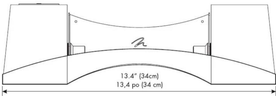
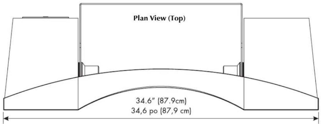
12" h × 34.6" w × 10.3" d (30.4 h × 87.9 w × 26.1 d cm)
Size (with mounting bracket / stand behind speaker)
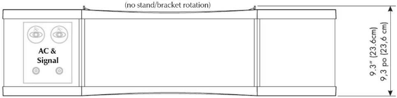
9.3" h × 34.6" w × 11.8" d (23.6 h × 87.9 w × 30 d cm)
Size (without mounting bracket)
9^ × 34.6^ × 10.3^ (22.7 h × 87.9 w × 26.1 d cm)
Your speaker is provided with an automatic Limited 90 Day Warranty coverage. You have the option, at no additional charge, to receive a Limited 5 Year Warranty coverage. To obtain the Limited 5 Year Warranty coverage you need to complete and return the Certificate of Registration, included with your speaker, and provide a copy of your dealer receipt, to MartinLogan within 30 days of purchase. For your convenience MartinLogan also offers online warranty registration at www.martinlogan.com.
MartinLogan may not honor warranty service claims unless we have a completed Warranty Registration card on file! If you did not receive a Certificate of Registration with your new speaker you cannot be assured of having received new units. If this is the case, please contact your authorized MartinLogan dealer.
Serial Number
Stage X's serial number is located near the binding posts.
Service
Should you be using your MartinLogan product in a country other than the one in which it was originally purchased, we ask that you note the following:
1 The appointed MartinLogan distributor for any given country is responsible for warranty servicing only on units distributed by or through it in that country in accordance with its applicable warranty.
2 Should a MartinLogan product require servicing in a country other than the one in which it was originally purchased, the end user may seek to have repairs performed by the nearest MartinLogan distributor, subject to that distributor's local servicing policies, but all cost of repairs (parts, labor, transportation) must be borne by the owner of the MartinLogan product.
3 If, after owning your speaker for six months, you relocate to a country other than the one in which you purchased your speaker, your warranty may be transferable. Contact MartinLogan for details.
*Specifications are subject to change without notice.
natural_image
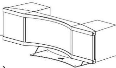
Technical line drawing of a mechanical bracket or support structure (no text or symbols)Dimensions: On Stand (stand/bracket beneath speaker)
text_image
Plan View (Top) 13.4" (34cm) 13,4 po (34 cm)Front Elevation
(no stand/bracket rotation)
text_image
AC & Signal (AC & Signal, Power, Current) 8.94" (22.7 cm) 8.94 po (22.7 cm) 11.97" (30.4 cm) 11.97 po (30.4 cm)Side Elevation
Dimensions: No Rotation Max. Dimensions: Rotated Down Max. Dimensions: Rotated Up
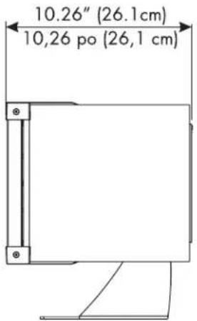
text_image
10.26" (26.1cm) 10,26 po (26,1 cm)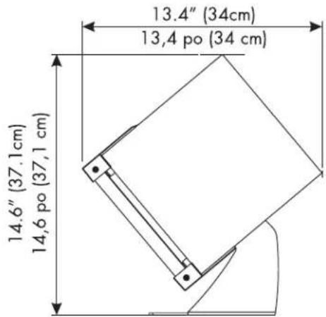
text_image
13.4" (34cm) 13,4 po (34 cm) 14.6" (37.1cm) 14,6 po (37,1 cm)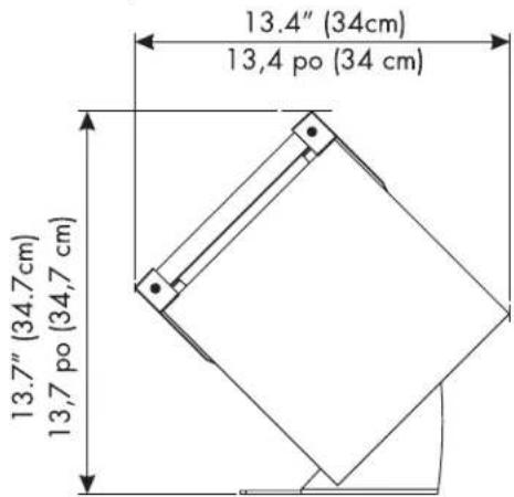
text_image
13.4" (34cm) 13,4 po (34 cm) 13.7" (34.7cm) 13,7 po (34,7 cm)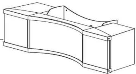
natural_image
Technical line drawing of a mechanical component with curved and rectangular sections (no text or symbols)Dimensions: Wall Mounting (stand/bracket behind speaker)
text_image
Plan View (Top) 34.6" (87.9cm) 34,6 po (87,9 cm)Front Elevation
text_image
(no stand/bracket rotation) AC & Signal 9.3" (23,6cm) 9,3 po (23,6 cm)Side Elevation
Dimensions: No Rotation Max. Dimensions: Rotated Down Max. Dimensions: Rotated Up
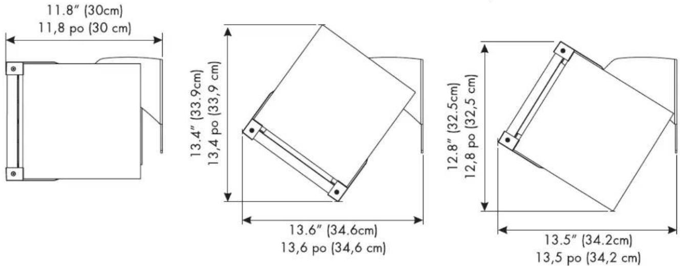
11.8" (30cm)
11,8 po (30 cm)
AC. Abbreviation for alternating current.
Active crossover. Uses active devices (transistors, IC's, tubes) and some form of power supply to operate.
Amplitude. The extreme range of a signal. Usually measured from the average to the extreme.
Arc. The visible sparks generated by an electrical discharge.
Bass. The lowest frequencies of sound.
Bi-Amplification. Uses an electronic crossover, or line-level passive crossover, and separate power amplifiers for the high and low frequency loudspeaker drivers.
Capacitance. That property of a capacitor which determines how much charge can be stored in it for a given potential difference between its terminals, measured in farads, by the ratio of the charge stored to the potential difference.
Capacitor. A device consisting of two or more conducting plates separated from one another by an insulating material and used for storing an electrical charge. Sometimes called a condenser.
Clipping. Distortion of a signal by its being chopped off. An overload problem caused by pushing an amplifier beyond its capabilities. The flat-topped signal has high levels of harmonic distortion which creates heat in a loudspeaker and is the major cause of loudspeaker component failure.
CLS. The abbreviation for curvilinear linesource.
Crossover. An electrical circuit that divides a full bandwidth signal into the desired frequency bands for the loudspeaker components.
dB (decibel). A numerical expression of the relative loudness of a sound. The difference in decibels between two sounds is ten times the Base 10 logarithm of the ratio of their power levels.
DC. Abbreviation for direct current.
Diffraction. The breaking up of a sound wave caused by some type of mechanical interference such as a cabinet edge, grill frame or other similar object.
Diaphragm. A thin flexible membrane or cone that vibrates in response to electrical signals to produce sound waves.
Distortion. Usually referred to in terms of total harmonic distortion (THD) which is the percentage of unwanted harmonics of the drive signal present with the wanted signal. Generally used to mean any unwanted change introduced by the device under question.
Driver. See transducer.
Dynamic Range. The range between the quietest and the loudest sounds a device can handle (often quoted in dB).
Efficiency. The acoustic power delivered for a given electrical input. Often expressed as decibels/watt/meter (dB/w/m).
ESL. The abbreviation for electrostatic loudspeaker.
Headroom. The difference, in decibels, between the peak and RMS levels in program material.
Hybrid. A product created by the marriage of two different technologies. Meant here as the combination of a dynamic woofer with an electrostatic transducer.
Hz (Hertz). Unit of frequency equivalent to the number of cycles per second.
Imaging. To make a representation or imitation of the original sonic event.
Impedance. The total opposition offered by an electric circuit to the flow of an alternating current of a single frequency. It is a combination of resistance and reactance and is measured in ohms. Remember that a speaker's impedance changes with frequency, it is not a constant value.
Inductor. A device designed primarily to introduce inductance into an electrical circuit. Sometimes called a choke or coil.
Linearity. The extent to which any signal handling process is accomplished without amplitude distortion.
Midrange. The middle frequencies where the ear is the most sensitive.
Passive crossover. Uses no active components (transistors, IC's, tubes) and needs no power supply (AC, DC, battery) to operate. The crossover in a typical loudspeaker is of the passive variety. Passive crossovers consist of capacitors, inductors and resistors.
Phase. The amount by which one sine wave leads or lags a sec-
ond wave of the same frequency. The difference is described by the term phase angle. Sine waves in phase reinforce each other; those out of phase cancel.
Pink noise. A random noise used in measurements, as it has the same amount of energy in each octave.
Polarity. The condition of being positive or negative with respect to some reference point or object.
RMS. Abbreviation for root mean square. The effective value of a given waveform is its RMS value. Acoustic power is proportional to the square of the RMS sound pressure.
Resistance. That property of a conductor by which it opposes the flow of electric current, resulting in the generation of heat in the conducting material, usually expressed in ohms.
Resistor. A device used in a circuit to provide resistance.
Resonance. The effect produced when the natural vibration frequency of a body is greatly amplified by reinforcing vibrations at the same or nearly the same frequency from another body.
Sensitivity. The volume of sound delivered for a given electrical input.
Stator. The fixed part forming the reference for the moving diaphragm in a planar speaker.
THD. The abbreviation for total harmonic distortion. (See Distortion)
TIM. The abbreviation for transient intermodulation distortion.
Transducer. Any of various devices that transmit energy from one system to another, sometimes one that converts the energy in form. Loudspeaker transducers convert electrical energy into mechanical motion.
Transient. Applies to that which lasts or stays but a short time. A change from one steady-state condition to another.
Tweeter. A small drive unit designed to reproduce only high frequencies.
Wavelength. The distance measured in the direction of progression of a wave, from any given point characterized by the same phase.
White noise. A random noise used in measurements, as it has the
same amount of energy at each frequency.
Woofer. A drive unit operating in the bass frequencies only. Drive units in two-way systems are not true woofers but are more accurately described as being mid/bass drivers.
TABLE DES MATIÈRES ET INTRODUCTION
Table des matières Introduction
natural_image
Illustration of a person sitting on a chair facing a TV with multiple monitors, no text or symbols presentnatural_image
Technical line drawing of a mechanical assembly with directional arrows indicating motion (no text or symbols)natural_image
Technical line drawing of a mechanical clamp or bracket assembly (no text or symbols)natural_image
Four identical electric drill motors arranged in a row, no text or symbols visiblenatural_image
Illustration of a hand using a tool to lift a pipe into a rectangular pipe (no text or symbols)natural_image
Pure geometric diagram of a curved structural component with no text, numbers, or symbols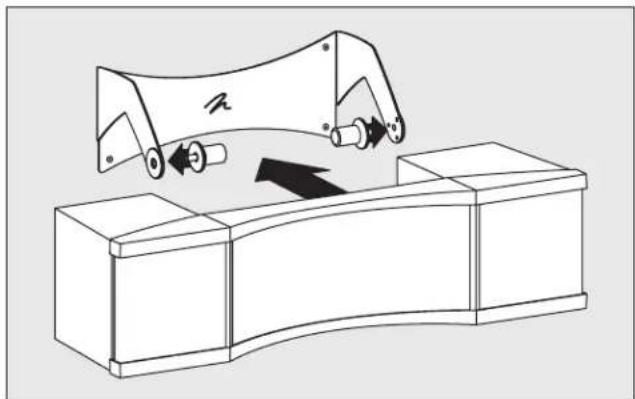
natural_image
Technical line drawing of a mechanical assembly with no visible text or symbolsnatural_image
Top-down view of a person reclining in a recliner seat with multiple speakers and equipment (no text or symbols visible)text_image
Surround Cone Dust Cap Voice Coil Former Basket Assembly Spider Magnet Voice Coil Magnet Gap Magnet Assemblynatural_image
Technical line drawing of a mechanical bracket or support structure (no text or symbols)natural_image
Technical line drawing of a mechanical component with curved and rectangular sections (no text or symbols)WARNING! Do not use your Stage X loudspeakers outside of the country of original sale—voltage requirements vary by country. Improper voltage can cause damage that will be potentially expensive to repair. The Stage X is shipped to authorized MartinLogan distributors with the correct power supply for use in the country of intended sale. A list of authorized distributors can be accessed at www.martinlogan.com or by emailing info@martinlogan.com.