
KTE101 - Capacitive sensor IFM - Free user manual and instructions
Find the device manual for free KTE101 IFM in PDF.


User questions about KTE101 IFM
0 question about this device. Answer the ones you know or ask your own.
Ask a new question about this device
Download the instructions for your Capacitive sensor in PDF format for free! Find your manual KTE101 - IFM and take your electronic device back in hand. On this page are published all the documents necessary for the use of your device. KTE101 by IFM.
USER MANUAL KTE101 IFM
Operating instructions
Touch sensor
Lamp
KTExxx
KTVxxx
Contents
1 Preliminary note 3
1.1 Symbols used 3
2 Safety instructions.... 4
3 Intended use.... 5
3.1 Application area 5
4 Function 6
4.1 Measuring principle (not applicable to KTV) 6
4.2 Operating modes 6
4.2.1 IO-Link 6
4.2.2 SIO mode 7
4.3 Switch-on and switch-off delay 7
4.3.1 Switch-on delay dS 7
4.3.2 Switch-off delay dr. 7
4.4 Operating modes (not applicable to KTV) 7
4.4.1 Dynamic mode (300 ms pulse) 7
4.4.2 Static mode.... 8
4.4.3 Bistable mode 8
4.4.4 Combined mode 8
4.5 Digital inputs 8
4.6 LED triggering.... 8
4.7 LED behaviour 9
4.8 LED mode.... 10
4.8.1 Button (not applicable to KTV) 10
4.8.2 Button/Input 10
4.8.3 PDOut / PLC-controlled.... 11
4.9 Internal temperature 11
4.10 Switching cycles counter (not applicable to KTV) 11
4.11 Operating hours counter 11
5 Installation.... 12
6 Electrical connection.... 14
7 Set-up 16
8 Parameter setting 17
8.1 Adjustable parameters 17
8.1.1 Sensor parameters 17
8.1.2 Configuration of the switching outputs.... 18
8.1.3 Indication parameters 18
8.1.4 Other parameters 20
8.2 Commands 21
8.3 Active events and device status 21
9 Troubleshooting 22
10 Maintenance, repair and disposal 23
1 Preliminary note
You will find instructions, technical data, approvals, accessories and further information using the QR code on the device / packaging or at documentation.ifm.com.
1.1 Symbols used
√ Requirement
Instructions
Reaction, result
[...] Designation of keys, buttons or indications
→ Cross-reference

Important note
Non-compliance may result in malfunction or interference.

Information
Supplementary note
2 Safety instructions
- The unit described is a subcomponent for integration into a system.
- The system architect is responsible for the safety of the system.
-
The system architect undertakes to perform a risk assessment and to create documentation in accordance with legal and normative requirements to be provided to the operator and user of the system. This documentation must contain all necessary information and safety instructions for the operator, the user and, if applicable, for any service personnel authorised by the architect of the system.
-
Read this document before setting up the product and keep it during the entire service life.
- The product must be suitable for the corresponding applications and environmental conditions without any restrictions.
- Only use the product for its intended purpose (→ Intended use).
- If the operating instructions or the technical data are not adhered to, personal injury and/or damage to property may occur.
- The manufacturer assumes no liability or warranty for any consequences caused by tampering with the product or incorrect use by the operator.
- Installation, electrical connection, set-up, operation and maintenance of the product must be carried out by qualified personnel authorised by the machine operator.
- Protect units and cables against damage.
- The device complies with the standard EN 61000-6-4 and is a class B product. The device may cause radio interference in domestic areas. If interference occurs, the user must take appropriate actions.
- At ambient temperatures above 55 °C or in direct sunlight, higher surface temperatures may occur, 76 °C for plastic devices and 58 °C for metal devices (DIN EN ISO 13732-1:2008-12).
3 Intended use
3.1 Application area
While in use the products are exposed to influences which may have an effect on function, life, quality and reliability of the product.
It is the customer's responsibility to ensure that the products are suitable for the intended application. This applies in particular to applications in hazardous areas and with adverse environmental influence such as pressure, chemicals, temperature fluctuations, moisture and radiation as well as mechanical stress, especially if the products are not installed properly.
Using the products in applications where the safety of people depends on the function of the product is not permitted. If these instructions are not adhered to, death or severe injury may occur.

Incorrect installation may lead to incorrect switching.
▶ Observe chapter Set-up.
▶ Check proper function by an application test.

Only when installed with the E12840 FDA seal (available as accessory), the device is compliant with FDA.

The device is not suitable for use on IO-Link masters with port class B.
4 Function
KTE type devices
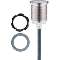
KTE type devices are capacitive touch sensors that respond to actuation with the tap of a finger, for example Measuring principle (not applicable to KTV) ( → ☐ 6).
KTV type devices
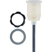
KTV type devices only function as lamps and feature the same design as the KTE type devices. They are designed to visualise application or plant states. The lack of a capacitive electrode system and associated evaluation in the KTVs is the main difference between the two products.
4.1 Measuring principle (not applicable to KTV)
An electric field is generated in front of the active electrode of the device. This field can be influenced by liquid and solid, conductive and non-conductive materials.
The change in capacitance is detected and converted into a switching signal. This is normally done by an approaching hand or finger.
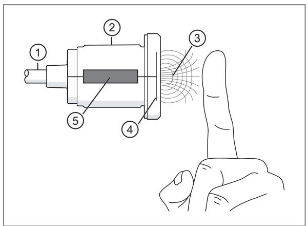
1: Connection
2: Housing
3: Alternating electric field
4: Electrode system
5: Evaluation electronics
The device operates by detecting changes in capacitance.
▶ Keep the detection range of the device clear when switching it on.
4.2 Operating modes
4.2.1 IO-Link
IO-Link is a communication system for connecting intelligent sensors and actuators to automation systems. IO-Link is standardised in the IEC 61131-9 standard.
General information on IO-Link at io-link.ifm
Input Output Device Description (IODD) with all parameters, process data and detailed descriptions of the device at documentation.ifm.com
IO-Link offers the following advantages:
• Interference-free transmission of all data and process values
• Parameter setting in the running process or presetting outside the application
- Parameters for identifying the connected devices in the system
• Additional parameters and diagnostic functions
• Automatic backup and restore of parameter sets in case of device replacement (data storage)
- Logging of parameter sets, process values and events
• Device description file (IODD - Input Output Device Description) for easy project planning
• Standardised electrical connection - Remote maintenance
4.2.2 SIO mode
The SIO mode is always active when the device is not connected to an IO-Link master.
In SIO mode, the device operates as a digital switch, using the digital switching output and the two digital inputs.

The configuration of the digital switching output (normally closed / normally open, PNP / NPN) can be changed via IO-Link. The device can then be operated without IO-Link.
4.3 Switch-on and switch-off delay
Depending on the operating mode, switch-on and switch-off delays are not available.
4.3.1 Switch-on delay dS
The switch-on delay for the switching output can be set between 0 and 2 s in steps of 100 ms. For this purpose, the device must be touched for at least the set time.
This function provides additional protection against unintentional activation of the output and can also be used as a button lock.
4.3.2 Switch-off delay dr
The switch-off delay for the switching output can be set between 0 and 3600 s in steps of 100 ms. The switching status of the device remains unchanged until the set time has elapsed.
A renewed actuation of the device has no effect on the switching output during the output delay [dr].
4.4 Operating modes (not applicable to KTV)
The following operating modes are available:
- Dynamic mode
- Static mode
- Bistable mode
- Combined mode

The device can only be configured via IO-Link.
4.4.1 Dynamic mode (300 ms pulse)
In the [Dynamic mode] setting, any detected actuation (activation) is signalled by a 300 ms output pulse. The output pulse can be delayed using the [dS] setting (switch-on delay). If the switch-on delay time is longer than the duration of the activation, no output pulse is produced. The [dr] (switch-off delay) setting is not available.
4.4.2 Static mode
In the [Static mode] setting, any detected actuation (activation) is signalled as long as the activation is present. The output pulse can be delayed using the [dS] setting (switch-on delay). If the switch-on delay time is longer than the duration of the activation, no output pulse is produced. The output pulse can be extended using the [dr] setting (switch-off delay).
4.4.3 Bistable mode
In the [Bistable mode] setting, any detected actuation (activation) changes the switching status. The switching status change can be delayed using the [dS] setting (switch-on delay). If the switch-on delay time is longer than the duration of the activation, no switching status change is produced. The [dr] (switch-off delay) setting is not available.
4.4.4 Combined mode
If the switching outputs are configured as normally open [High active], the following applies:
Switching status OFF:
- Tap: on for 300 ms (minimum switch-on time).
• Continuous activation: on for the duration of the activation.
• Double tap: on (continuously ON).
Switching status ON:
- Tap: off, switch-on lock for 300 ms (because of the double tap).
• Continuous activation: off. - Double tap: off.
The dS (switch-on delay) and dr (switch-off delay) settings are not available.
When configured as normally closed [Low active], the switching statuses are inverted.

A double tap is defined as two short, consecutive actuations within the 300 ms time window defined for this purpose.
4.5 Digital inputs
The digital inputs are designed to IEC/EN 61131-2, type 3 with ratiometric thresholds. For UB 8...32 V this means:
- The switching status OFF is reliably detected at an input voltage <= 20 % * UB .
- The switching status ON is reliably detected at an input voltage >= 80 % * UB .

Device actuation has priority over digital input signals.
4.6 LED triggering
The following table shows which colour is displayed for each combination of device status and [LED mode].
| Status | Device not actuated | Device actuated *) | ||||
| Input | IN1 | [3CDS] |  |  |  |   |
| IN2 |  |  | [HW04] | [46D0] |   | |
| [LED mode] | [Button/Input] | [LED colour. Button not pressed] | [LED colour. Button pressed] | |||
| [Inputs] | [LED colour. Button not pressed] | [LED colour. IN1 only] | [LED colour. IN2 only] | [LED colour. IN1 and IN2] | ||
| [PDOut / PLC-controlled] | [PDOut / PLC-controlled] | |||||
Tab. 1: Overview of device status and LED mode
*) not applicable to KTV.

In [LED mode] [PDOut / PLC-controlled], colour selection is exclusively via the IO-Link master. Device actuations are transmitted to the IO-Link master via the SSC bit * .
▶ For a colour change on actuation, the logic must be implemented in the higher-level controller (polling of the SSC bit, colour selection depending on the state of the SSC bit).

The LED colours are defined via the parameter [LED colour] Indication parameters ( → 18).
| LED colour | Preset for |
| Off (0) | Device not actuated. |
| Blue (1) | IN1 and IN2 active. |
| Green (2) | Device actuated (not applicable to KTV). |
| Cyan (3) | - |
| Red (4) | IN1 active and IN2 inactive. |
| Purple (5) | - |
| Yellow (6) | IN2 active and IN1 inactive. |
| White (7) | - |
| Amber (8) | - |
| Custom colour 1 (9) | Red: 252, Green: 0, Blue: 197 (magenta colour) |
| Custom colour 2 (10) | Red: 254, Green: 40, Blue: 0 (orange colour) |
Tab. 2: Available LED colours
4.7 LED behaviour
The LED behaviour can be set via the parameter [LED behaviour].
The following parameters are available:
- Continuous lighting
- Slow flashing
• Medium-fast flashing - Fast flashing
- Slow pulsing
• Medium-fast pulsing - Fast pulsing
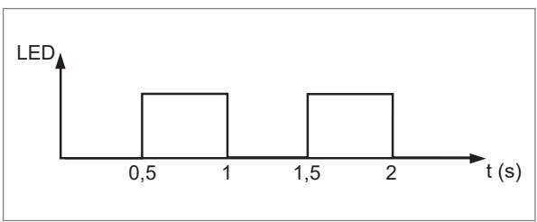
Fig. 1: LED behaviour when flashing medium fast

Fig. 2: LED behaviour when pulsing medium fast
4.8 LED mode
4.8.1 Button (not applicable to KTV)
In this mode, the LED of the connected device cannot be changed via PDOut (IO-Link) or the inputs.
This function can be used to integrate signals from other sensors or mechanical contacts into the IO-Link network.
If the device is integrated into the IO-Link network, the signals at IN1 (pin2) and IN2 (pin5) can be used to evaluate the switching outputs.
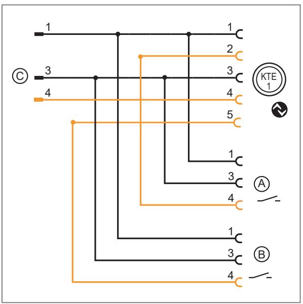
Fig. 3: LED mode button connection example
Possible connection accessories - EVC847 and EVC848.
A: Sensor A
B: Sensor B
C: IO-Link master
4.8.2 Button/Input
In this mode, the LED of the connected device can be changed via the inputs.
This function can be used to display plant states via the device.
The LED behaves as specified in LED triggering ( → LED triggering ☐ 8).

Fig. 4: LED mode button/input connection example
Possible connection accessories - EVC847 and EVC848.
A: Sensor A
B: Sensor B
C: IO-Link master
4.8.3 PDOut / PLC-controlled
In this mode, the LED of the connected device can only be changed via PDOut (IO-Link).
4.9 Internal temperature
The internal temperature of the device can be read. Other parameters ( → ☐ 20).

Due to the internal heating of the device, the internal temperature usually does not correspond to the ambient temperature.
4.10 Switching cycles counter (not applicable to KTV)
The number of switching cycles can be read and reset Other parameters ( → ☐ 20). The switching cycles counter is cyclically stored in the memory of the device. The readings can be used for reference after restarting the device, but may show lower values due to the storage cycle of approx. 60 minutes.
4.11 Operating hours counter
The number of operating hours can be read from the memory of the device via IO-Link Other parameters ( → ☐ 20).
5 Installation
A: Stainless steel device
B: Plastic device with symbol disc
C: Plastic device with transparent symbol disc and symbol sticker
A
B

©
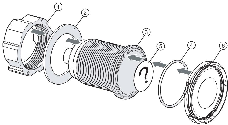
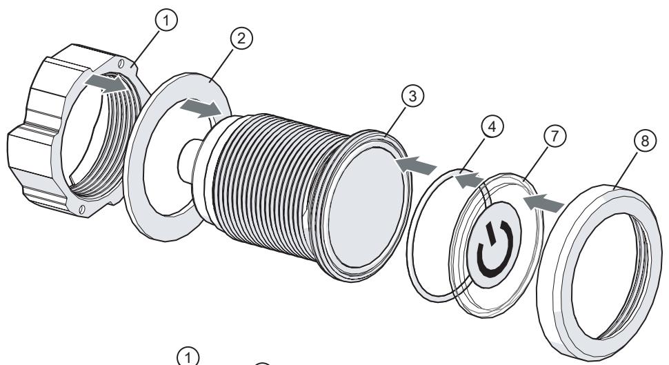
Fig. 5: Observe assembly, sequence and direction of installation
1: Easy mount nut
2: Sealing ring (outer)
3: Touch sensor
4: Sealing ring (inner)
5: Symbol sticker
6: Plastic symbol disc (with and without symbol)
7: Symbol disc for stainless steel devices
8: Stainless steel ring

When operated without a symbol disc, actuations will not be reliably detected.
▶ Always operate the device with a symbol disc.

In case of improper assembly, water, dirt or similar can penetrate between the symbol disc and the sensing face and cause malfunction.
▶ Assemble the device and symbol disc when removed.
▶ Always install the device and symbol disc with the appropriate seals.
▶ The seal must lie completely in the groove provided.
▶ Screw on the symbol disc with a tightening torque of at least 1 Nm.

Before set-up, ensure that the symbol disc is installed with a tightening torque of 1 Nm. This can be achieved by manual tightening. Over-tightening by hand is ruled out by the design.

Every device is compatible with every symbol disc. For example, a plastic symbol disc can be mounted on a metal device.
6 Electrical connection

The unit must be connected by a qualified electrician.
▶ Observe the national and international regulations for the installation of electrical equipment.
▶ Disconnect power.
▶ Connect the unit as follows:
KTE type:

Fig. 6: Cable wiring
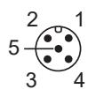
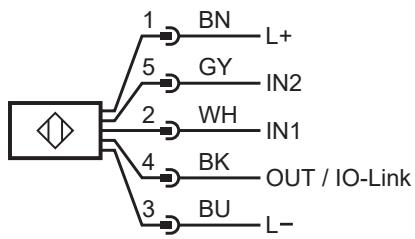
Fig. 7: Connector wiring
KTV type

Fig. 8: Cable wiring

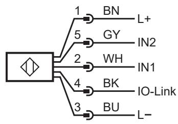
Fig. 9: Connector wiring

▶ Lay the cable as straight as possible and do not coil it.
7 Set-up
▶ Install the device completely.
▶ Check the electrical connection.
▶ Make the required settings.
▶ Check the function of the device.
8 Parameter setting
Parameters can be set before installation or during operation.

If you change parameters during operation, this will influence the function of the plant.
▶ Ensure that there will be no malfunctions in your plant.
During parameter setting the unit remains in the operating mode. It continues to monitor with the existing parameter until the parameter setting has been completed.

Depending on the parameter setting, the parameters available in the menu may change.
Requirements for parameter setting via the IO-Link interface:
√ A suitable parameter setting software, e.g. ifm moneo|configure
√ The Input Output Device Description (IODD) for the device, see documentation.ifm.com
√ One IO-Link master
▶ Connect the IO-Link master to a parameter setting software.
▶ Set the port of the master to the IO-Link operating mode.
▶ Connect the device to a free port of the IO-Link master.
▷ The unit switches to IO-Link mode.
▶ Change parameter settings in the software.
▶ Write parameter settings to the unit.

Notes on parameter setting → Manual of the parameter setting software
8.1 Adjustable parameters

The following IO-Link parameters merely provide an overview. The complete list can be found in the IODD of the device.
8.1.1 Sensor parameters
| Parameter | Value / Factory setting | Description |
| Sensitivity | Low (0)Medium (1)High (2) | Setting the device's sensitivity to touch in 3 levels. |
| Environment setting | Soiling (0)Standard (1)Splash water (2) | Setting the ambient conditions. Soiling: The device detects actuations regardless of soiling, i.e. by dirt, oil and wet solutions with limited conductivity. Signal processing is the least stringent in this setting. Standard: Compromise setting between "Soiling" and "Splash water". It offers limited protection against soiling and splash water and detects most actuations. Splash water: The device is resistant to splash water. Incorrect switching is avoided. This includes fine mist, rain, washing and wiping/cleaning with a damp cloth. A certain degree of protection against accidental switch-on is provided. Signal processing is the most stringent in this setting. |
| Sensitivity | Environment setting | Actuation possible (with): | Not triggered by: | Suppresses soiling: | |||||||||||
| Without gloves | Thin gloves (e.g. latex gloves) | Medium gloves (e.g. gardening gloves) | Thick gloves (e.g. work gloves) | Spray | Rain | Thin water jet (e.g. from cleaning bottle) | High-pressure cleaner | Moist wiping | Water jet (garden hose or more) | Soiling (e.g. oil or grease, no water) | Wet soiling, non-conductive (e.g. demineralised water) | Wet soiling, slightly conductive (e.g. tap water) | Wet soiling, highly conductive (e.g. seawater) | ||
| Low | Soiling | √ | √ | × | × | √ | √ | × | √ | × | × | √ | √ | × | × |
| Standard | √ | √ | × | × | √ | √ | √ | √ | × | √ | √ | √ | × | × | |
| Splash water | √ | √ | × | × | √ | √ | √ | √ | √ | √ | √ | √ | × | × | |
| Medium | Soiling | √ | √ | √ | √ | √ | √ | × | × | × | × | √ | √ | × | × |
| Standard | √ | √ | √ | √ | √ | √ | √ | √ | × | × | √ | √ | × | × | |
| Splash water | √ | √ | √ | √ | √ | √ | √ | √ | √ | √ | √ | √ | × | × | |
| High | Soiling | √ | √ | √ | √ | √ | √ | × | × | × | × | √ | √ | √ | × |
| Standard | √ | √ | √ | √ | √ | √ | √ | × | × | × | √ | √ | × | × | |
| Splash water | √ | √ | √ | √ | √ | √ | √ | √ | √ | × | √ | √ | × | × | |
8.1.2 Configuration of the switching outputs
| Parameter | Value / Factory setting | Description |
| P-n | PNP (0)NPN (1) | Output polarity for the switching outputs. |
| SSC Config Logic | High active (0)Low active (1) | The switch point logic of the device is set by touch. |
| SSC1 Delay. dS | 0 s ... 2 s | Switch-on delay for SSC1, adjustable in steps of 0.1 s. |
| SSC1 Delay. dr | 0 s ... 3600 s | Switch-off delay for SSC1, adjustable in steps of 0.1 s. |
| SSC1 Counter | 0 ... 2147482880 | Counts the number of switching cycles. Can only be read. Can be reset via system command 209: “Reset SSC1 Counter to 0” |
| SSC1 Totaliser | 0 ... 2147482880 | Counts the number of switching cycles. Can only be read. Reset not possible. |
8.1.3 Indication parameters
The device's LED display can be completely or partially deactivated.
| Parameter | Value / Factory setting | Description |
| LED mode | Button/Input (0)Inputs (11)*PDOut / PLC-controlled (3) | Definition of the source used for controlling the LED.*Factory setting for KTV |
| LED brightness | Normal (0)Bright (1) | Brightness of the LEDs |
| RGB custom colour 1 | Red (RGB - red component 0...255): 252 Green (RGB - green component 0...255): 0 Blue (RGB - blue component 0...255): 197 | Colour defined by the customer (1) |
| RGB custom colour 2 | Red (RGB - red component 0...255): 254 Green (RGB - green component 0...255): 40 Blue (RGB - blue component 0...255): 0 | Colour defined by the customer (2) |
| LED colour. Button not pressed | Off (0)Blue (1)Green (2)Cyan (3)Red (4)Purple (5)Yellow (6)White (7)Amber (8)Custom colour 1 (9)Custom colour 2 (10) | LED colour for the status:• Device not actuated. |
| LED behaviour. Button not pressed | Continuous lighting (0)Slow flashing (1)Medium-fast flashing (2)Fast flashing (3)Slow pulsing (4)Medium-fast pulsing (5)Fast pulsing (6) | LED behaviour for the status:• Device not actuated. |
| LED colour. IN2 only | Off (0)Blue (1)Green (2)Cyan (3)Red (4)Purple (5)Yellow (6)White (7)Amber (8)Custom colour 1 (9)Custom colour 2 (10) | LED colour for the status:• IN2 active and IN1 inactive. |
| LED behaviour. IN2 only | Continuous lighting (0)Slow flashing (1)Medium-fast flashing (2)Fast flashing (3)Slow pulsing (4)Medium-fast pulsing (5)Fast pulsing (6) | LED behaviour for the status:• IN2 active and IN1 inactive. |
| LED colour. IN1 only | Off (0)Blue (1)Green (2)Cyan (3)Red (4)Purple (5)Yellow (6)White (7)Amber (8)Custom colour 1 (9)Custom colour 2 (10) | LED colour for the status:• IN1 active and IN2 inactive. |
| LED behaviour. IN1 only | Continuous lighting (0)Slow flashing (1)Medium-fast flashing (2)Fast flashing (3)Slow pulsing (4)Medium-fast pulsing (5)Fast pulsing (6) | LED behaviour for the status:IN1 active and IN2 inactive. |
| LED colour. IN1 and IN2 | Off (0)Blue (1)Green (2)Cyan (3)Red (4)Purple (5)Yellow (6)White (7)Amber (8)Custom colour 1 (9)Custom colour 2 (10) | LED colour for the status:IN1 active and IN2 active. |
| LED behaviour. IN1 and IN2 | Continuous lighting (0)Slow flashing (1)Medium-fast flashing (2)Fast flashing (3)Slow pulsing (4)Medium-fast pulsing (5)Fast pulsing (6) | LED behaviour for the status:IN1 active and IN2 active. |
| LED colour. Button pressed | Off (0)Blue (1)Green (2)Cyan (3)Red (4)Purple (5)Yellow (6)White (7)Amber (8)Custom colour 1 (9)Custom colour 2 (10) | LED colour for the status:Device actuated. |
| LED behaviour. Button pressed | Continuous lighting (0)Slow flashing (1)Medium-fast flashing (2)Fast flashing (3)Slow pulsing (4)Medium-fast pulsing (5)Fast pulsing (6) | LED behaviour for the status:Device actuated. |
8.1.4 Other parameters
| Parameter | Value / Factory setting | Description |
| Internal temperature | -30 ... 90 °C | Internal temperature of the device. |
| Switch-on operations | 0 ... 2000000 | Number of switch-on operations. |
| Operating hours | 0 ... 2000000 h | Number of operating hours. |
8.2 Commands
| Command | Description |
| Reset to factory settings | Resets all parameters of the device to the factory settings. The switching cycles counter is not reset. |
| Reset counter to zero | Resets the switching cycles counter to 0. |
| Locator Start | The visual indicators (LEDs) of the device are switched to the localization display pattern, making it easier to spot a device in an application. |
| Locator Stop | The localization indication pattern is stopped. |

Unless deactivated earlier via a command, the flashing function [Locator] is automatically deactivated after 10 minutes.
8.3 Active events and device status
In addition to the device status, which is contained in the process data input, the device also outputs events. The events can be evaluated with an IO-Link master.
| Event | Device status | Description |
| Device OK | OK (0) | The device is working properly. |
| Parameter error | Function check (3) | A parameter written to the device has the wrong value range or the wrong length. |
| Internal temperature exceeded | Out of specification (2) | Internal temperature too high.► ▶ Reduce ambient temperature► ▶ Reduce load► ▶ Switch LED off |
| Internal temperature not reached | Out of specification (2) | Internal temperature too low.► ▶ Insulate device |

More information on the events → IODD.
9 Troubleshooting
▶ Clean the device to remove any soiling.
▶ Check the correct installation of the device.
▶ Carry out a reset.
▶ Check the seals.
▶ If necessary, adjust the sensitivity or environment setting.
▶ If necessary, set a switch-on delay.
10 Maintenance, repair and disposal
If used correctly, the unit is maintenance-free.
▶ Keep the sensing face and any clear spaces free from deposits and foreign bodies.
▶ It is not possible to repair the unit.
▶ After use, dispose of the unit in an environmentally friendly way in accordance with the applicable national regulations.
- 1 PRELIMINARY NOTE
- 1.1 SYMBOLS USED
- 2 SAFETY INSTRUCTIONS
- 3 INTENDED USE
- 3.1 APPLICATION AREA
- 4 FUNCTION
- 4.1 MEASURING PRINCIPLE (NOT APPLICABLE TO KTV)
- 4.2 OPERATING MODES
- 4.2.1 IO-LINK
- 4.2.2 SIO MODE
- 4.3 SWITCH-ON AND SWITCH-OFF DELAY
- 4.3.1 SWITCH-ON DELAY DS
- 4.3.2 SWITCH-OFF DELAY DR
- 4.4 OPERATING MODES (NOT APPLICABLE TO KTV)
- 4.4.1 DYNAMIC MODE (300 MS PULSE)
- 4.4.2 STATIC MODE
- 4.4.3 BISTABLE MODE
- 4.4.4 COMBINED MODE
- 4.5 DIGITAL INPUTS
- 4.6 LED TRIGGERING
- 4.7 LED BEHAVIOUR
- 4.8 LED MODE
- 4.8.1 BUTTON (NOT APPLICABLE TO KTV)
- 4.8.2 BUTTON/INPUT
- 4.8.3 PDOUT / PLC-CONTROLLED
- 4.9 INTERNAL TEMPERATURE
- 4.10 SWITCHING CYCLES COUNTER (NOT APPLICABLE TO KTV)
- 4.11 OPERATING HOURS COUNTER
- 5 INSTALLATION
- 6 ELECTRICAL CONNECTION
- 7 SET-UP
- 8 PARAMETER SETTING
- 8.1 ADJUSTABLE PARAMETERS
- 8.1.1 SENSOR PARAMETERS
- 8.1.2 CONFIGURATION OF THE SWITCHING OUTPUTS
- 8.1.3 INDICATION PARAMETERS
- 8.1.4 OTHER PARAMETERS
- 8.2 COMMANDS
- 8.3 ACTIVE EVENTS AND DEVICE STATUS
- 9 TROUBLESHOOTING
- 10 MAINTENANCE, REPAIR AND DISPOSAL
Brand : IFM
Model : KTE101
Category : Capacitive sensor