MWDUL-10CRN1-BCJ4 - Air Conditioning MIDEA - Free user manual and instructions
Find the device manual for free MWDUL-10CRN1-BCJ4 MIDEA in PDF.

User questions about MWDUL-10CRN1-BCJ4 MIDEA
0 question about this device. Answer the ones you know or ask your own.
Ask a new question about this device
Download the instructions for your Air Conditioning in PDF format for free! Find your manual MWDUL-10CRN1-BCJ4 - MIDEA and take your electronic device back in hand. On this page are published all the documents necessary for the use of your device. MWDUL-10CRN1-BCJ4 by MIDEA.
USER MANUAL MWDUL-10CRN1-BCJ4 MIDEA
Item No. 817036 SKU No. 21615016 Model NO. MWDUL-10CRN1-BCJ4
natural_image
Line drawing of a server rack unit with ventilation slots and control panel (no text or symbols)Free 3 months
extension of the
original limited warranty
period!* Simply text a
picture of your proof of
purchase to:
1-844-224-1614
"The certainly sclerent is for the human pacific
the component of the product's original warranty
periods. Individuals do not need to register the
practice in order to go all the rights and retective
of registered owners under the original financial
marty
Limited Warranty
1 year an
Garantie Limitée
WINDOW AIR CONDITIONER Owner's Manual
Our customer service staff is available to help you. For any problem with your purchase, or to receive further information about this product, please call our toll-free number.
SAVE THIS MANUAL
Keep this manual and the original sales invoice in a safe, dry place for future reference.
- SAFETY PRECAUTIONS......2
- OPERATING INSTRUCTIONS....5
- INSTALLATION INSTRUCTIONS....9
- CARE AND CLEANING .... 18
- TROUBLESHOOTING....19
- REMOTE CONTROL OPERATING INSTRUCTIONS....20
- WARRANTY 29
Read this Manual
You will find inside many helpful tips on how to use and maintain your air conditioner properly. Just a little preventice care on your part can save you a great deal of time and money over the life of your air conditioner. You'll find many answers to common problems in the Troubleshooting chart. Reviewing this chart first may prevent you from calling for service.

CAUTION
- Contact the authorized service technician for repair or maintenance of this unit.
- Contact the installer for installation of this unit.
- The air conditioner is not intended for use by young children or disabled persons without supervision.
- Young children should be supervised to ensure that they do not play with the air conditioner.
- If the power cord is to be replaced, replacement work shall be performed by authorized personnel only.
- Installation work must be performed in accordance with the national wiring standards by authorized personnel only.
Safety Precautions
To prevent injury to the user or other people and property damage, the following instructions must be followed. Incorrect operation due to failure to following the instructions may cause harm or damage. The severity level is classified as follows:
 WARNING WARNING | This symbol indicates a risk of death or serious injury. |
 CAUTION CAUTION | This symbol indicates a risk of injury or damage to property. |
■ Meanings of symbols used in this manual are as shown below.
 | Never do this. |
 | Always do this. |

WARNING
① Plug in the power plug properly.
- Otherwise, it may cause electric shock or fire due to excess heat generation.
Do not operate or stop the unit by inserting or pulling out the power plug.
- It may cause electric shock or fire due to heat generation.
Do not damage or use an unspecified power cord.
- It may cause electric shock or fire.
- If the power cord is damaged, it must be replaced by the manufacturer or an authorized service centre or a similarly qualified person in order to avoid a hazard.
Do not modify the power cord's length or share the outlet with other appliance.
- It may cause electric shock or fire due to heat generation.
Do not operate with wet hand or in a damp environment.
- It may cause electric shock.
Do not direct airflow at room occupants only.
- This may be harmful to your health.
① Always ensure proper grounding.
- Incorrect grounding may cause electric shock.
Do not allow water to run into electric parts.
- It may cause failure of the unit or electrical shock.
① Always install a circuit breaker and a dedicated power circuit.
- Incorrect installation may cause fire and electric shock.
① Unplug the unit in the presence of strange sounds, smell, or smoke.
- A damaged unit may cause fire and electric shock.
Do not use the socket if it is loose or damaged.
- It may cause fire and electric shock.
Do not open the unit during operation.
- It may cause electric shock.
① Keep firearms away.
- It may cause fire.
Do not place the power cord close to heating appliances.
- It may cause fire and electric shock.
Do not use the power cord near flammable gas or combustibles, such as gasoline, benzene, thinner, etc.
- It may cause an explosion or fire.
① Ventilate the room before operating the air conditioner if there is a gas leak from another appliance.
- It may cause an explosion, fire, and burns.
Do not disassemble or modify the unit.
- It may cause failure of the unit and electric shock.
Safety Precautions

CAUTION
When the air filter is to be removed, do not touch the metal parts of the unit.
- It may cause an injury.
When the unit is to be cleaned, switch it off and turn off the circuit breaker.
- Do not clean the unit when the power is ON as it may cause fire, electric shock, and even an injury.
Stop operating the unit and close the window during storms or hurricanes.
- Operation with windows opened may cause indoor wetting and soaking of household furniture.
Do not place obstacles around the air inlet or inside the air outlet.
- It may cause failure of the unit or an accident.
Do not use abrasive detergents, such as wax or thinner, but use a soft cloth.
- The appearance may deteriorate due to discoloration or surface scratches of the product.
① Use caution when unpacking and installing. Sharp edges could cause injury.
Do not clean the air conditioner with water.
- Water may enter the unit and degrade the insulation. It may cause electric shock.
Do not put a pet or house plant where it will be exposed to direct air flow.
• This could harm the pet or plant.
① Disconnect the power cord by pulling it out by the plug.
- It may cause electric shock and damage.
① Ensure that the installation bracket of the outdoor appliance is not damaged due to prolonged exposure.
- A damaged bracket may cause the unit to overturn.
Do not place heavy objects on the power cord and ensure that the cord is not compressed.
- It may cause fire or electric shock.
① Ventilate the room properly when used together with a stove, etc..
- An oxygen deficiency may occur.
Do not use for any other purpose than air cooling.
- Do not use this air conditioner to preserve precision devices, food, pets, plants, and art objects. It may cause deterioration of quality, etc.
Turn off the main power switch when not using unit for a long time.
- It may cause failure of the unit or fire.
① Always insert the filters securely. Clean the filter every two weeks.
- Operation without filters may cause failure of the unit.
Do not drink water drained from the air conditioner.
- It contains contaminants and could make you sick.
Safety Precautions
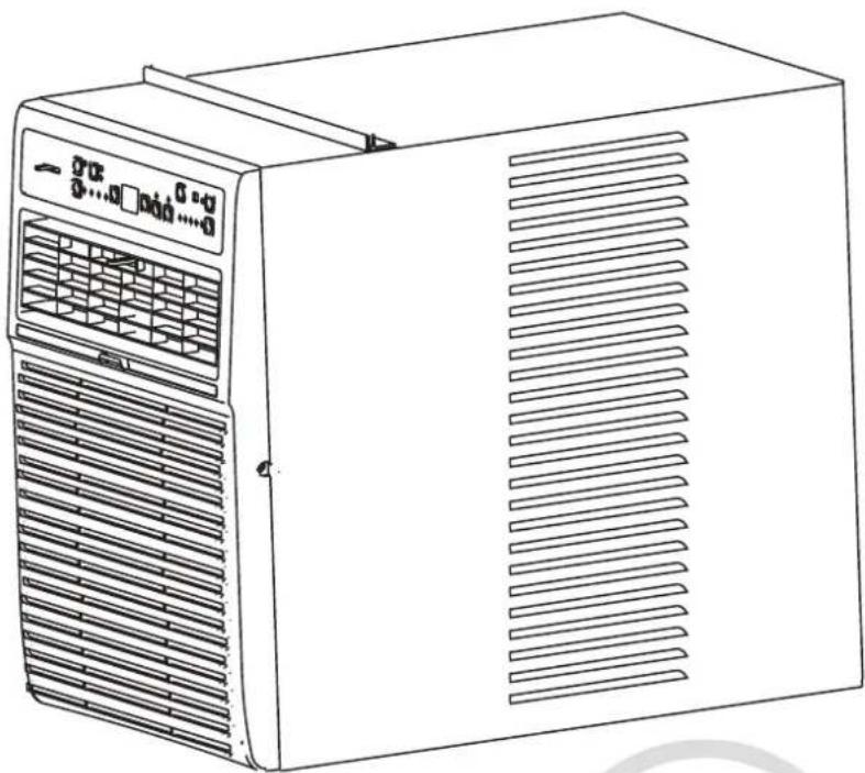
NOTE The power cord with this air conditioner contains a current detection device designed to reduce the risk of fire. Please refer to the section "Operating the Current Device" for details. In the event that the power cord is damaged, it cannot be repaired. It must be replaced with a cord from the product manufacturer.
text_image
NEVER cut, remove, or bypass the grounding prong of the plug. Power supply cord with three-prong grounding plug and current detection deviceWARNING For your Safety
- Do not store or use gasoline or other flammable vapours and liquids in the vicinity of this or any other appliance.
- Avoid fire hazard or electric shock. Do not use an extension cord or adaptor plug. Do not remove any prong from the power cord.
▲WARNING Electrical Information
- Be sure the electrical service is adequate for the model you have selected. This information can be found on the serial plate, which is located on the side of the cabinet and behind the grille.
- Be sure the air conditioner is properly grounded. To minimize shock and fire hazard, proper grounding is important. The power cord is equipped with a three-prong grounding plug for protection against shock hazard.
- Your air conditioner must be plugged into a properly grounded wall receptacle. If the wall receptacle you intend to use is not adequately grounded or protected by a time-delay fuse or circuit breaker, have a qualified electrician install the proper receptacle.
- Ensure the receptacle is accessible after installing the unit.
- Do not run the air conditioner without the side protective cover in place.
This could result in mechanical damage within the air conditioner. Do not use and extension cord or adapter plug.
Operating the of Current Device
(Applicable to the current detection device only)
The power cord contains a current device that detects damage to the power cord. To test your power supply cord, perform the following:
- Plug in the air conditioner.
- The power supply's plug has TWO buttons. By pressing the TEST button, you will hear a click as the RESET button pops out.
- Press the RESET button again to hear another click sound as the button engages.
4 The power cord is now supplying electricity to the unit.(On some models, the plug is equipped with a light indicating that the power is ON.)
NOTES:
- Do not use this device to turn the unit on or off.
- Always make sure the REST button is pushed in for proper operation.
- The power supply must be replaced if it fails reset if the TEST button is pushed or it cannot be rest. Please contact Customer Service.
- If the power cord is damaged, it cannot be repaired. It MUST be replaced with a new cord. Please contact Customer Service.
Operating Instructions
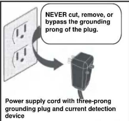
Normal Sounds
text_image
High Pitched Chatter High efficiency compressors may have a high pitched chatter during the cooling cycle. Sound of Rushing Air At the front of the unit, you may hear the sound of rushing air being moved by the fan. Gurgle/Hiss Gurgling or hissing noise may be heard due to refrigerant passing through the evaporator during normal operation. Vibration The unit may vibrate and make noise because of poor wall or window construction, or incorrect installation. Pinging or Switching Droplets of the water hitting the condenser during normal operation may cause pinging or switching sounds.NOTE: All the illustrations in this manual are for explanation purposes only. Your air conditioner may be slightly different, but its functions are the same.
NOTE: This air conditioner is designed to be operated under the following conditions:
| Cooling operation | Outdoor temp: | 18-43°C/64-109°F |
| Indoor temp: | 17-32°C/62-90°F |
NOTE: Performance may be reduced outside of these operating temperatures.
Operating Instructions
NOTE: The following instructions refer to the unit controls the same instructions can be used for the remote control.
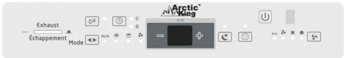
Unit Control Panel
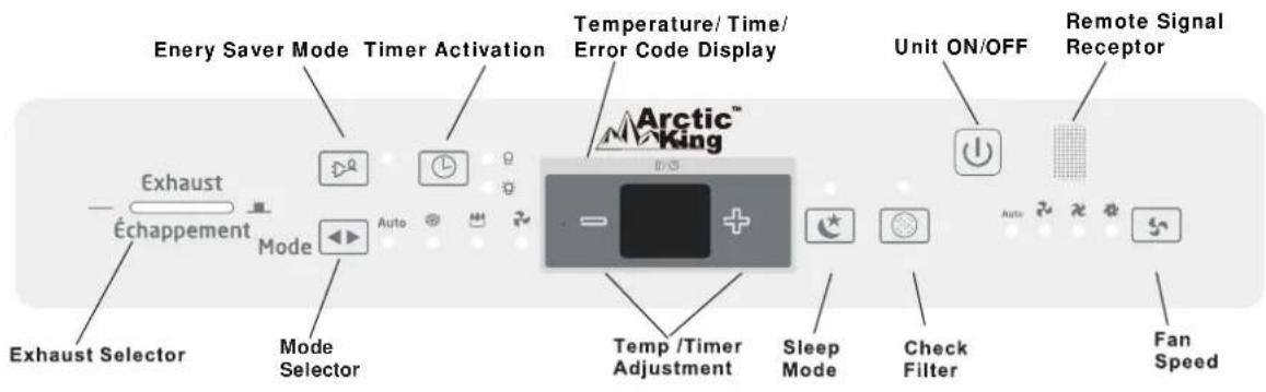
text_image
Enery Saver Mode Timer Activation Temperature/ Time/ Error Code Display Unit ON/OFF Remote Signal Receptor Exhaust Échappement Mode Arctic™ King Auto Temp /Timer Adjustment Sleep Mode Check Filter Fan Speed Exhaust Selector Mode Selector
ON/OFF Button
The unit will initiate automatically the ENERGY SAVER function under COOL ✗, DRY 🎨, and AUTO (AUTO COOL and AUTO FAN only) modes.


UP/DOWN Button
Press or hold the left (<) or right (>) button until the desired temperature is displayed. This temperature will be automatically maintained anywhere between 62°F (17°C) and 86°F (30°C). If you want the display to read the actual room temperature, refer to the "Operating the Fan Only" section.
NOTE: This appliance provides a features that will allow you to set and display temperatures in Celsius or Fahrenheit. To change the temperature display on the main unit, press the left (<) and right(>) button to simultaneously for 3 seconds to alternate between the °C & °F scale.

FAN Button
This mode selects the fan speed in four steps: AUTO, LOW, MED, or HIGH. Each button press shifts the fan speed mode. For some models, the fan speed cannot be adjusted under and HEAT mode. On DRY mode, the fan speed is automatically at LOW.

Energy Saver Button
This function is available on COOL, DRY, AUTO (only AUTO-COOLING and AUTO-FAN) modes. The fan will continue to run for 3 minutes after the compressor shuts off. The fan then cycles on for 2 minutes at 10-minute intervals until the room temperature is above the set temperature, at which time the compressor turns back on and cooling starts.

SLEEP Button
In this mode, the selected temperature will increase by 2^/1^ 30 minutes after the mode is selected. The temperature will then increase by another 2^/1^ after an additional 30 minutes. This new temperature will be maintained for 6 hours before it returns to the originally selected temperature. This ends the SLEEP mode and the unit will continue to operate as originally programmed. The SLEEP mode program can be cancelled at any time during operation by again pressing the SLEEP button again.
Operating Instructions

MODE Button
- To choose the operating mode, press the MODE button. At each button press, a mode is selected in a sequence that goes from AUTO, COOL DRY and FAN. The indicator light will illuminate and remain ON once the mode is selected.
To operate on AUTO mode:
- When you set the air conditioner in AUTO mode, it will automatically select COOL, HEAT (on some models only), or FAN ONLY operation depending on the temperature you have selected and the room temperature.
- The air conditioner will automatically control the room temperature around the temperature point set by you.
- In this mode, the fan speed cannot be adjusted, it starts automatically at a speed according to the room temperature.
To operate on FAN ONLY mode:
- Use this function only when cooling is not desired, such as for room air circulation or to exhaust stale air (on some models). Remember to open the vent during this function, but keep it closed during cooling for maximum cooling efficiency. You can choose any fan speed.
- During this function, the display will show the actual room temperature, not the set temperature as in the cooling mode.
- In FAN ONLY mode, the temperature cannot be adjusted.
To operate on DRY mode:
- In this mode, the air conditioner will operate as a dehumidifier. Since the conditioned space is a closed or sealed area, there will still be some degree of cooling.

TIMER Button
- When the unit is ON or OFF, first press the TIMER button. The TIMER ON indicator light will illuminate, indicating that the AUTO-START program has been initiated.
- When the TIMER ON time is displayed, press the TIMER button again. The TIMER OFF indicator light will illuminate, indicating that the AUTO-STOP program has been initiated.
- Press or hold the UP or DOWN button to change the AUTO time in 0.5-hour increments, up to 10 hours, then 1-hour increments up to 24 hours. The control will count down the remaining time until start.
- The selected time will register in 5 seconds and the system will automatically revert back to display the previous temperature setting or room temperature when the unit is on. When the unit is OFF, there is no display.
- Turning the unit ON or OFF at any time or adjusting the timer setting to 0.0 will cancel the AUTO/ STRAT/ STOP timed program.

CHECK FILTER Button
This feature is a reminder to clean air filter for more efficient operation. The LED light will illuminate after 250 hours of operation. To reset after cleaning the filter, press the CHECK FILTER button and the light will go OFF.
Operating Instructions
Display:
Shows the set temperature in "°C" or "°F" and the AUTO TIMER settings. While on Fan only mode, it shows the room temperature.
Error Codes:
AS-Room temperature sensor error-Unplug the unit and plug it back in. If error repeats, call for service. NOTE: The FAN ONLY mode will display LO or HI.
-Evaporator temperature sensor error-Unplug the unit and plug it back in. If error repeats, call for service.
HS -Electric heating sensor error-Unplug the unit and plug it back in.If error repeats, call for service.
Additional Features you You Should Know
Now that you have mastered the operating procedure, here are more features in your control that you should become familiar with.
- The COOL circuit has and automatic 3-minute starting time if the unit is turn OFF and ON quickly. This prevents overheating of the compressor and possible circuit breaker tripping. The fan will continue to run during this time.
- The control can display the temperature in Fahrenheit or Celsius.
To convert from one to the other, press and hold the left and right TEMP/TIMER buttons at the same time for 3 seconds.
Exhaust Control
text_image
Arctic King Exhaust Échappement Mode Auto + - AutoThis EXHAUTST CONTROL allows the air conditioner to either circulate air inside or vent air to the outside.
The closed position is used when maximum cooling is desired. It may also be used for air recirculation without cooling when the air conditioner is set in any FAN position.
The open position removes stale air from the room and vents it to the outside. Fresh air is drawn in through normal openings in the home.
4-Way Louvers
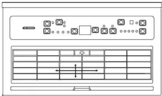
natural_image
Top-down schematic of a ventilation system with fan, vent, and control panel (no text or labels)The 4-Way air directional louvers allow you to direct air flow up or down, left or right throughout the room as needed. To adjust the air directional louvers side to side, use the center handle as you move it side to side.
Installation Instructions
NOTE: These instructions describe installation in a typical wood-framed window with a wood sliding sash or installation in a metal casement window. Modification may be necessary when installing windows made differently than those shown in these instructions.
A high window accessory kit is available for window heights up to 62" (1575mm).
Meeting Electrical Requirements

WARNING
Electrical Shock and Personal Injury Hazard
• This appliance must be grounded.
• DO NOT ground to a gas line.
- If the cold water pipe is obstructed by plastic, non-metallic gaskets, or other insulating material, DO NOT use for grounding.
- Check with a qualified electrician if you are not sure whether the appliance is properly grounded.
- DO NOT modify power cord plug. If it does not fit in the outlet, have a proper outlet installed by a qualified electrician.
- DO NOT have a fuse in the neutral or grounding circuit. A fuse in the neutral or grounding circuit could result in electrical shock.
- DO NOT use an extension cord with this appliance.
Failure to follow these instructions could result in electrical shock, serious injury, or death.
Observe all local governing codes and ordinances.
Do not, under any circumstances, remove the power cord grounding prong.
NOTE: If codes permit and a separate grounding wire is used, it is recommended that a qualified electrician determines that the grounding path is adequate and not obstructed by plastic, no-metallic gaskets, or other insulating materials.
Receptacle Wiring
Receptacle wiring rating should be at least 14. Use copper wire only. It is your responsibility to provide proper and adequate receptacle wiring, installed by a qualified electrician.
Electrical Requirements
A time-delay fuse or circuit breaker is also required. A separate circuit dedicated to this appliance MUST be provided.
Preparing for Installation
Installation Tips
For wood-frame casement windows: It may be necessary to build a frame, using at least 1-inch thick wood with a 15-1/2-inch wide opening.
For brick or cement building construction: It may be necessary to put a wood stool strip under the air conditioner or mounting purposes.
Tools Required (Not Included)
Flat head screwdriver
Phillips head screwdriver
Carpenter's level
Tape measure
Fine-tooth saw
Electric or hand drill
Installation Instructions
1. Make sure you have all the necessary parts.
Installation Kit Contents:
- Platform (1)
- Support brace (1)
- Adjustment bolt (1)
- Hex flange nut - 1/4" (1)
- Track seal (1)
- Side channel seal (1)
- Foam seal strip/sash seal
- Safety bracket (1)
9-11. Screw-2-1/2" (2), or Screw-1-3/4" (2), or Screw-1" (2) - Screw-3/4" (6)
- Screw-3/4" self-threading (7)
- Window lock bracket (1)
- Plastic window panel (1)
- Side channel (2)
- Screw-3/8"(6)
- Panel frame/seal assembly (1)
NOTE: Use the scale below to measure the length of your screws. The scale will come in handy when separating screws for installation.
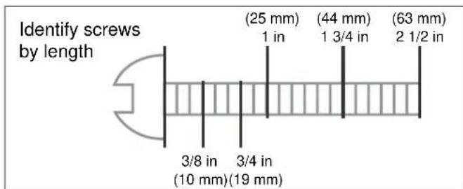
text_image
Identify screws by length (25 mm) 1 in (44 mm) 1 3/4 in (63 mm) 2 1/2 in 3/8 in 3/4 in (10 mm)(19 mm)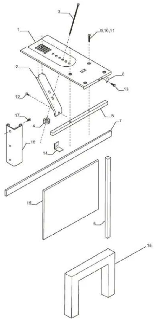
text_image
Exploded view diagram of a device with numbered parts for identification and assembly reference.2. Choose a proper sized window, as shown on the right.
• 15-1/2 in minimum width
- 16-1/4 in maximum width(for casement windows)
- 21-1/4 in minimum height (with window panel retainer)
- 20-5/16 in minimum height (window panel retainer removed)
• 39-7/16 in maximum height
NOTE: Height measurement must be for a clear opening above the mounting platform. In some cases, due to a variety of stop and track arrangements, the above dimensions may slightly vary if necessary, installation can be made by alternating window jambs (refer to "Alternate Window Jamb Installation" section).
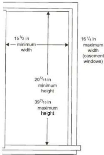
text_image
15½ in minimum width 20⁵/₁₆ in minimum height 39⁷/₁₆ in maximum height 16 ¼ in maximum width (casement windows)Installation Instructions
3. Choose the proper window location.
Choose a window that allows the cooled air to flow freely and directly into room(s) you wish to cool. Remember that it is difficult to move air around corners. Also choose a window that is within 6 feet of an electrical outlet (refer to "Meeting Electrical Requirements/Receptacle Wiring Needs" section). Do not use an extension cord.
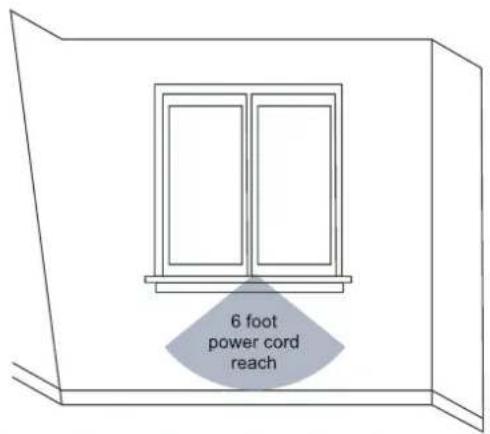
text_image
6 foot power cord reachInstalling the Unit in a Sliding Window
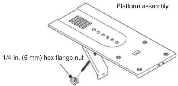
- Attach the support brace to platform as shown. Use the adjustment bolt and hex flange nut to complete the assembly. Choose slot and adjustment bolt hole locations that will create a 45-degree angle between the platform support brace. Fit the assembly in the window to determine if the platform will rest properly, and allow a allow proper slope (3/16-inch lower on the outside).
NOTE: If you are planning to use a siding protection board (refer to Step 5) on the outside of your house, hold the board in place when testing the assembly in window.
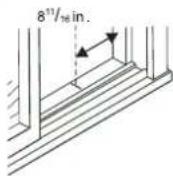
- Measure, and lightly mark a line 8-11/16" from the window jamb.
NOTE: If any sash stop protrudes more than 1" from the side window jambs, the 8-11/16" measurement must be increased accordingly. Screen and storm window frames may also require adjustments to the measurement.
- Center the platform assembly with the inside platform tab pressed against the inside edge of window track. Using the holes in the platform as a guide, mark and drill two 9/64" diameter holes. Drill holes in the track or stool.

CAUTION
Property damage hazard-Failure to comply with the following precautions could result in damage to the window or air conditioner. Be sure the wood stool or window track is securely attached to the building construction. Use longer screws in subframes if necessary.

text_image
assembly 1/4" (6 mm) hex flange nut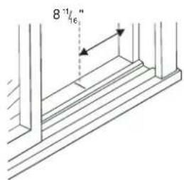
text_image
8°16"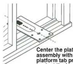
text_image
Center the plate assembly with platform tab pr against the injCenter the platform assembly with the platform tab pressed against the inside edge of the window track.
text_image
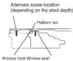
Alternate screw location (depending on the stool depth) Platform tab Window track Window seal1Installation Instructions
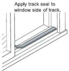
- Peel off protective backing from track seal. Apply seal to room side of window track. Center of seal strip should coincide with the line marked in Step 2. The two screw holes drilled in Step 3 should be directly above seal strip in the inner track.
- Securely attach a siding-protection board to side of house.
NOTE: Siding-protection board should be long enough to span two wall studs.
- Place the platform assembly, with platform tab against inside of window track, and attach it to window jamb. Use appropriate length screws (Items 9-11 in the "Preparing for Installation" section).
- Adjust the platform assembly so that it is tilted 3\~4° to the outside, as shown on the right. This ensures proper water drainage from the air conditioner.
- Level the platform assembly from side to side Also make sure the window track is level. Use leveling shims as necessary to ensure the unit is level from side to side.
- Measure the height of the window opening from the top of the platform assembly, as shown on the right. Subtract 20-5/8 in. Mark this measurement on the plastic window panel along the longer.side.
text_image
Apply track seal to window side of track.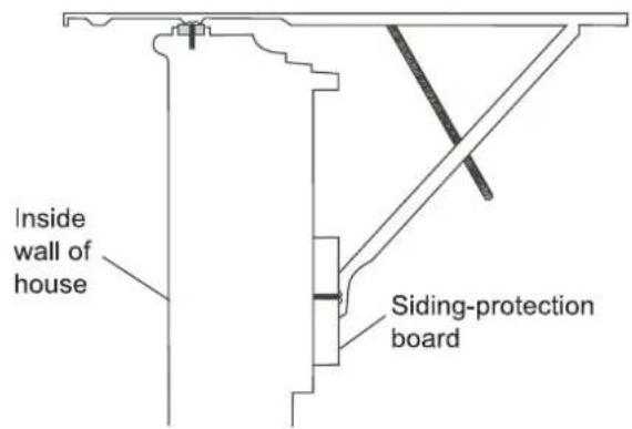
text_image
Inside wall of house Siding-protection board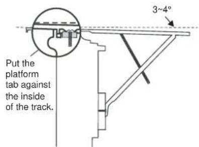
text_image
Put the platform tab against the inside of the track. 3~4°
text_image
Measure the distance and subtract 20 5/8 in.Installation Instructions
- Clamp the plastic window panel between a board and a work table, and cut along the cutting line with a fine-toothed saw. Remove any burrs with a file.
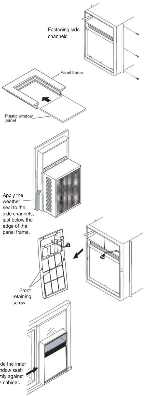
- Fasten side channels to the sides of the air conditioner using three screws (Item 17) per channel. Insert the first screw on the top of the channel. Make sure the channel hook ends face toward the back of the unit
- Slide plastic window panel into panel frame, with the smooth side towards the room. Slide the panel frame assembly into the side channels of the air conditioning cabinet. Make sure the retainer grooves of the plastic window panel are firmly enclosed on all sides.
- Cut the side channel seal into two equal lengths. Remove the protective backing and apply it to the rear side of the cabinet side channels, starting just below the panel frame assembly. Pinch off excess length so the seal is even with the bottom of the cabinet side channel.
-
To remove front:
-
Remove the two front retaining screws from the front frame.
- Gently pull the front out and lift up to release it from the case.
- Then release the coupler plugs.
NOTE: DO NOT push or pull air direction louvers.
- Place the air conditioner in the window opening, as shown on the right. It should sit on the platform assembly so that the window panel frame and cabinet side channels are against the top and side window jambs.
text_image
Fastening side channels Panel frame Plastic window panel Apply the weather seal to the side channels, just below the edge of the panel frame. Front retaining screw Side the inner window sash only against the cabinet.Installation Instructions
-
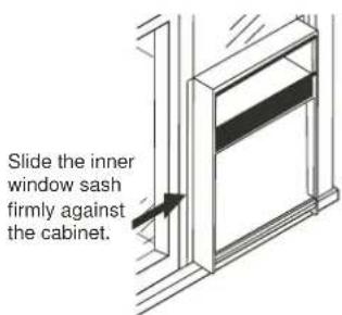
Slide the inner window sash firmly against the side of the cabinet. Make sure not to peel the seal strips from the window track and cabinet side channels. If the panel frame does not fit snugly to the inner window sash, secure the panel frame to the sash with 3/4-inch screws or 3/4-inch self-threading screws. Use the partially plugged holes in the panel frame. Drill 1/8-inch pilot holes for the screws.
-
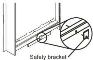
Hook the safety bracket over the base of the unit and fasten it to the front of the platform assembly. Use a 3/4-inch self-threading screw.
NOTE: The bracket prevents movement of the air conditioner (either in or out) after completing the installation.
-
Push the foam seal strip/sash seal between the vertical sash and window glass, as shown on the right
-
Use the window locking bracket to lock the inner window sash to the base of the outer window sash. Use a 3/4-inch screw or 3/4-inch self-threading screw. Drill a 1/8-inch pilot hole.
-
To replace the front:
First reconnect the coupler plugs, position the exhaust control through the front in the proper location. Then replace the retaining screws that hold the panel in place. Do not push or pull the front panel louvers.
text_image
Slide the inner window sash firmly against the cabinet.Install the safety bracket.
text_image
Safety bracket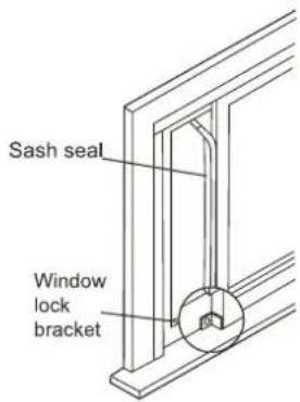
text_image
Sash seal Window lock bracketAlternate Window Jamb Applications
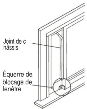
To install in windows without flanges or wood stops on the top and side jambs, the channels and panel frame must fit against a mating flange (or a 1/16-inch max. thick angle) attached to the window jambs. Figure A shows this angle installed. Figures B & C show alternate installations On the sash side of the opening, the leading corner of the inner sash becomes the flange. You can purchase the angle strip at your local hardware store.
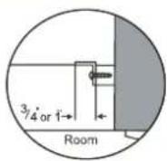
A
Add the angle t
wood stop
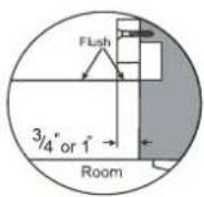
B
Add wood as shown
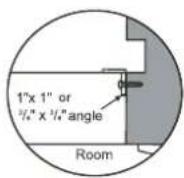
C
3/4-in. angle
Installation Instructions
Installing the Unit in a Casement Window
NOTE: Open the window fully to allow for clearance of the cabinet. The crank handle should be removed to allow the platform to be fastened to the jamb. If the window cannot open far enough (more than 15-1/2 inches) for the cabinet to clear the window, remove the window entirely by drilling out the rivets. Bolts can serve as pivots in the future.
To avoid crank handle and window clearance problems, the unit can be installed in a stationary sash section. However, the horizontal mullion and two-glass panels must be removed before installation.
- Attach the support brace to the platform as shown on the right. Use the adjustment bolt and hex flange nut to complete the assembly. Choose the slot and adjustment bolt hole locations that will create a 45-degree andle between the platform and support brace. angle assembly in the window to determine if the platform will rest properly and allow a proper slope (3/16-inch lower on the outside).
NOTE: If you are planning to use a siding-protection board (see Step 6) on the outside of your house, hold the board in place when testing the assembly in the window. - Drill a 9/64-inch diameter pilot hole in the window jamb at an equal distance from each side of the jamb, and 3/16 inches up from the window sill. If the hole aligns with the window lever slot in the jamb bottom, an additional hole will have to be drilled through the platform edge and window jamb to miss this slot.
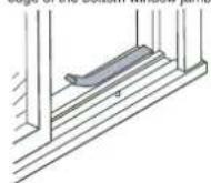
- Peel off the protective backing from the track seal and stick the seal to the window sill on the outside edge of the bottom window jamb
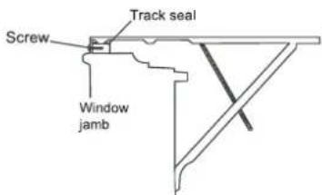
- Screw the paltform assembly to the window jamb through the pilot hole you drilled in Step 2. Use a 3/4-inch self-threading screw.
text_image
Platform assembly 1/4-in. (6 mm) hex flange nutEqual distance from both sides
Apply the track seal to the outside edge of the bottom window jamb.
text_image
Screw Track seal Window jambInstallation Instructions
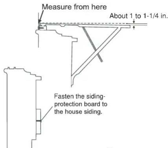
- Adjust the platform assembly so that the rear of the air conditioner is 3/16 in. lower than the front. This ensures proper water drainage from the air conditioner.
NOTE: Adjust the platform assembly so that the air conditioner is 1-1/8 in. to 1-1/2 in. lower than the front (tilted about 3-4 degrees downward to the outside). After proper installation, condensate should not drain from the overflow drain hole during normaluse. Otherwise, correct the slope. - Securely attach a siding-protection board to the side of the house where the platform assembly is in contact with the house. The siding-protection board should be long enough to span two wall studs.
- Measure the height of the window opening from the top of the platform assembly. Subtract 20-5/8 in. Mark this measurement on the plastic window panel along the longer side.
- Clamp the plastic window panel between a board and a work table, and cut along the cutting line with a fine-toothed saw. Remove any burrs with a file.
- Fasten the side channels to the sides of the unit using three screws (Item 17) per channel. Make sure channel hook ends face toward the back of the unit.
- Slide the plastic window panel into the panel frame with the smooth side towards the outside. Slide the panel frame assembly into the side channels of the air conditioner cabinet. Make sure the retainer grooves of the plastic window panel are firmly enclosed on all sides.
text_image
Measure from here About 1 to 1-1/4 in. Fasten the siding- protection board to the house siding.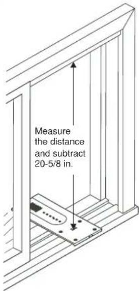
text_image
Measure the distance and subtract 20-5/8 in.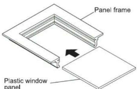
text_image
Panel frame Plastic window panelInstallation Instructions
-
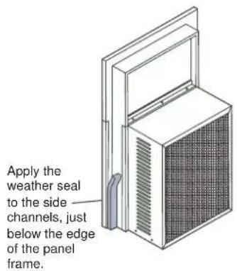
Cut the side channel seal into two equal lengths. Remove the protective backing and apply it to the rear side of the cabinet side channels, starting just below the panel frame assembly. Pinch off excess length so the seal is even with the bottom of the cabinet side channel.
-
To remove the front panel:
-
Remove the two front retaining screws from the front frame.
- Gently pull the front out and lift up to release it from the case.
- Then release the coupler plugs.
NOTE: DO NOT push or pull the air direction louvers.
-
Place the air conditioner in the window opening, as shown on the right. It should sit on the platform assembly so that the window panel frame and cabinet side channels are against the top and side window jambs. Side channels should overlap side window jambs equally.
-
Drill two 9/64-in diameter pilot holes in the top window jamb in line with the partially plugged holes in the panel frame. Secure the panel fame to the window jamb with two 3/4-inch self-threading screws. If additional holding is necessary, two screws may be used on the sides of the panel frame as well.
-
Drill two screw-clearance holes in the cabinet side channels (near bottom) and two 9/64-inch diameter pilot holes in the side window jambs. Secure the cabinet side channels to the window jambs with two 3/4-inch self-threading screws. When doing this, be careful not to twist the side channel seals with the screws.
NOTE: Inserting screws will prevent the air conditioner from being pushed into the room.
- To replace the front panel: Reconnect the coupler plugs and, position the exhaust control through the front in the proper location. Then replace the retaining screws that hold the panel in place. Do not push or pull the front panel louvers.
text_image
Apply the weather seal to the side channels, just below the edge of the panel frame.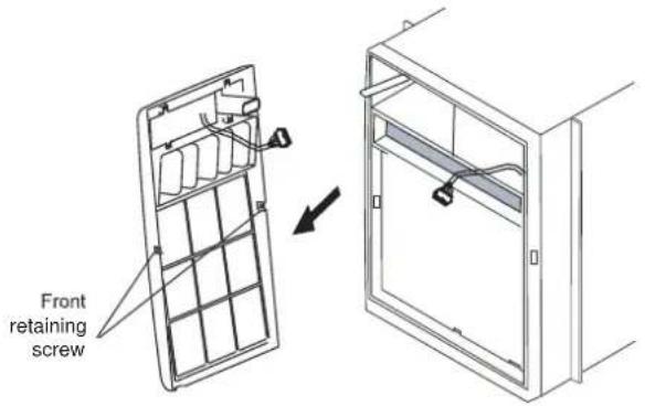
text_image
Front retaining screw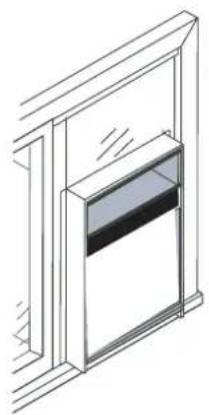
natural_image
Line drawing of a window with a recessed door and glass panel (no text or symbols)Care and Cleaning
CAUTION
Clean your air conditioner occasionally to keep it looking new. Be sure to unplug the unit before cleaning to prevent shock or fire hazards.
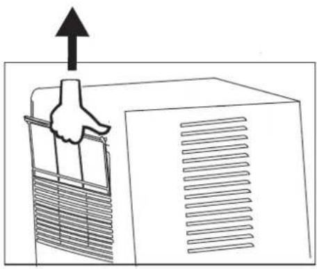
Air Filter Cleaning
natural_image
Diagram of a hand pressing down on a wall-mounted air conditioner unit with an upward arrow (no text or symbols)The air filter should be checked at least once a month to see if cleaning is necessary. Trapped particles in the filter can build up and cause an accumulation of frost on cooling coils.
- Grasp the filter by the center and pull up and out.
- Wash the filter using liquid dishwashing detergent and warm water. Rinse the filter thoroughly.
• Gently shake excess water from the filter. Be sure the filter is thoroughly dry before replacing. - You may vacuum the filter clean instead of washing it.
Note: Never use hot water over 40^ ( 104^ F) to clean the air filter. Never attempt to operate the unit without the air filter.
Cabinet Cleaning
- Be sure to unplug the air conditioner to prevent shock or fire hazards The cabinet and front may be dusted with an oil-free cloth or washed with a cloth moistened with a solution of warm water and mild liquid dishwashing detergent. Rinse thoroughly and wipe dry.
- Never use harsh cleaners, wax, or polish on the cabinet front.
- Be sure to wring excess water from the cloth before wiping around the controls. Excess water in or around the controls may cause damage to the air conditioner.
- Plug in air conditioner.
Winter Storage
- If you plan to store the air conditioner during winter, remove it carefully from the window according to the installation instructions. Cover it with plastic or store it in its original box.
NOTE: To prevent rust or electrical connections from being damaged, store the air conditioner in an upright position and in a dry place.
Troubleshooting
Before calling for service, review this list. It may save your time and money. This list includes common issues that are not the result of detective workmanship or materials in this appliance.
| Problem | Solution |
| Air conditioner does not start | Wall plug disconnected. Push the plug firmly into wall outlet. |
| House fuse blown or circuit breaker tripped. Replace the fuse with a time delay type or reset circuit breaker. | |
| Plug the tripped current device. Press the RESET button. | |
| Control is OFF. Turn on the control and set to the desired setting. | |
| Unit turned OFF and then ON too quickly. Turn the unit off and wait 3 minutes before restarting. | |
| Air from unit does not feel cold enough. | Room temperature below 17°C (62 °F). Cooling may not occur until the room temperature raises about 17°C (62 °F). |
| Temperature sensing element touching the cold coil located behind air filter. Straighten the tube away from the coil. | |
| Reset to a lower temperature. | |
| Compressor shut-off by changing modes. Wait approximately 3 minutes and listen for the compressor to restart when set in the COOL mode. | |
| Air conditioner cooling, but room is too warm. Ice forming on cooling coil behind decorative front. | Outdoor temperature below 18°C(64°F). To defrost the coil, set to FAN ONLY mode. |
| The air filter may be dirty. Clean the filter. Refer to the "Care and Cleaning" section. To defrost, set to FAN ONLY mode. | |
| Thermostat set too cold for nighttime cooling. To defrost the coil, set to FAN ONLY mode. Then set temperature to a higher setting. | |
| Air conditioner cooling, but room is too warm. NO ice forming on cooling coil behind decorative front. | Dirty air filter- air restricted. Clean air filter. Refer to the "Care and Cleaning section". |
| Temperature set too high. Set the temperature to a lower setting. | |
| Air directional louvers positioned improperly. Position louvers for better air distribution. | |
| Front of units blocked by drapes, blinds, furniture, etc. restricting air distribution. Clear blockage in front of the unit. | |
| Doors, windows, registers, etc. open. Cold air escape. Close doors, windows, registers. | |
| Unit recently turned ON in hot room. Allow additional time to let "stored heat" release room walls, ceilings, floor, and furniture. | |
| Air conditioner turns ON and OFF rapidly. | Dirty air filter. Air restricted. Clean the air filter. |
| Outside temperature extremely hot. Set the FAN speed to a higher setting to bring air past cooling coils more frequently. | |
| Noise when unit is cooling. | Air movement sound. This is normal. If too loud, set to a lower FAN setting. |
| Window vibration. Poor installation. Refer to the "Installation Instructions" section or check with the installer. | |
| Water dripping INSIDE when unit is cooling. | Improper installation. Tilt the air conditioner slightly to the outside to allow water drainage. Refer to the "Installation Instructions" section or check with the installer. |
| Water dripping OUTSIDE when unit is cooling. | Unit removing large quantity of moisture from humid room. This is normal during excessively humid days. |
| Remote sensing deactivating prematurely (some models). | Remote control not located within range. Place the remote control within 16.4 feet & 180-degree radius in front of the unit. |
| Remote control signal obstructed. Remove the obstruction. | |
| Room too cold. | Set temperature too low. Increase the set temperature. |
Remote Control Operating Instructions
Handling the Remote Controll
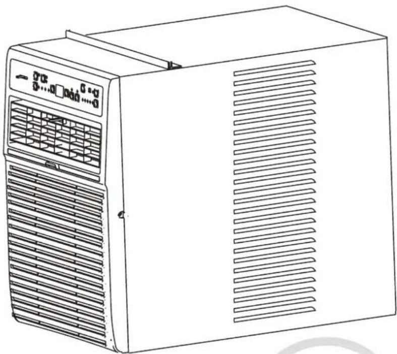
natural_image
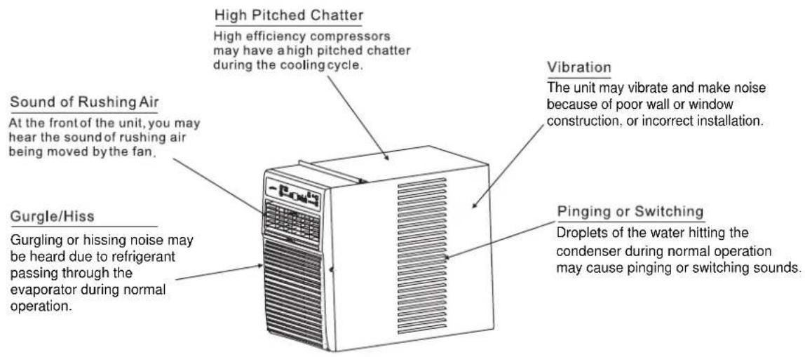
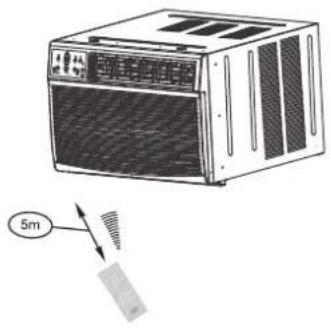
Illustration of a white industrial air conditioner unit with ventilation grilles and a 5m scale indicator (no text or symbols on the device itself)Location of the Remote controll.
- Use the remote controll within a distance of 16 feet (5 m) from the appliance, pointing it towards the receiver. The reception is confirmed by a beep.
CAUTIONS
- The air conditioner will not operate if curtains, doors, or other materials block the signals from the remote controller to the indoor unit.
- Prevent any liquid from falling into the remote controll. Do not expose the remote controll to direct sunlight or heat.
- If the infrared signal receiver on the indoor unit is exposed to direct sunlight, the air conditioner may not function properly. Use curtains to prevent the sunlight from shining on the receiver.
- If other electrical appliances react to the remote controller, either move these appliances or consult your local dealer.
Battery Installation Instructions
NOTE: First remove the insulation piece (if available) and then install the battery according to the following steps.
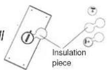
Step 1: Insert a coin vertically in the groove on the battery cover, clockwise rotation of 45 degrees, make sure that the groove is aligned with the "unlock" sign as shown below and remove the battery cover.
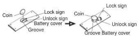
text_image
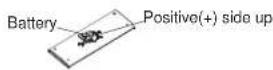
Coin Lock sign Unlock sign Battery cover Groove → Coin Lock sign Unlock sign Groove Battery coverStep 2: Install battery inside the remote controller, the positive (+) side up.
Step 3: Install the battery cover, make sure the battery cover groove is aligned with the "unlock" sign. Insert a coin vertically in the groove and press it gently, then counter clockwise rotation of 45 degrees, make sure the groove is aligned with the "lock" sign as shown below.
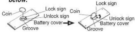
text_image
below Coin Lock sign Unlock sign Battery cover Groove Coin Lock sign Unlock sign Battery cover GrooveRemote Control Operating Instructions
WARNING
- The battery must be disposed of properly. Do not short circuit or dispose of in fire.
- Keep batteries out of the reach of children.
- Batteries must not be ingested.
- Non-rechargeable batteries are not to be recharged.
- Exhausted batteries are to be removed from the product.
Remote Controller Specifications
| Model | RG15A(B)/E |
| Rated Voltage | 3.0 V ( lithium battery CR2025 ) |
| Lowest Voltage of CPU Emitting Signal | 2.4 V |
| Signal Receiving Range | 16 ft (5 m) |
| Environment | -5 °C~60 °C (23 F~140 F) |
NOTE:
-Design of buttons is based on the typical model and might be slightly different from the actual one you purchased. In such case, the shape shall prevail.
-All the functions described in these instructions apply to the different available air conditioner models. If your model doesn't have a specific function, pressing the corresponding button will have no effect.
-If a function description between the "Remote Control Operating Instructions" and USERS MANUAL is significantly different, the USER MANUAL description shall prevail.

WARNING: Chemical Burn Hazard. Keep batteries away from children."
"This product contains a lithium button/coin cell battery. If a new or used lithium button/coin cell battery is swallowed or enters the body, it can cause severe internal burns and can lead to death in as little as 2 hours. Always completely secure the battery compartment. If the battery compartment does not close securely, stop using the product, remove the batteries, and keep it away from children. If you think batteries might have been swallowed or placed inside any part of the body, seek immediate medical attention."
The cells shall be disposed of properly, including keeping them away from children. Even used cells may cause injury.
Remote Control Operating Instructions
NOTE:
Function buttons
ON/OFF Button
Operation starts when this button is pressed and stops when the button is pressed again. NOTE: If the unit has THE ENERGY SAVER function, it will initiate automatically the under COOL, DRY, and AUTO (AUTO COOL and AUTO FAN) modes.
TEMP DOWN Button
Push this button to decrease the indoor temperature setting in 1^ C/ 1^ F increments up to 17^ C/ 62^ F.
TIMER Button
Push this button to activate the "AUTO-START" or "AUTO STOP" program.
ONE TOUCH Button
Push this button and the system will automatically shift to COOL operation with the auto fan speed. The set temperature is 26^ C/ 80^ F and the timer setting program will be cancelled.
MODE Button
Press this button to select the desired operation mode from AUTO, COOL, DRY, HEAT (cooling & heating models only), and FAN.
NOTE: Do not select the HEAT mode if the machine you purchased is the cooling only type. The heat mode is not supported by the cooling only appliance.
TEMP UP Button
Push this button to increase the temperature setting in 1^ C/ 1^ F increments up to 30^ C/ 86^ F.
FAN Button
Push this button to select the fan speed in four steps: AUTO, LOW, MED and HIGH.
SLEEP button
Press this button to activate the SLEEP mode. This function is available under the COOL, HEAT, or AUTO mode only and maintains the most comfortable temperature for you.
ENERGY SAVER Button
Press this button to activate the energy-saving mode. Press it again to stop the function (on some models).
Remote Control Operating Instructions
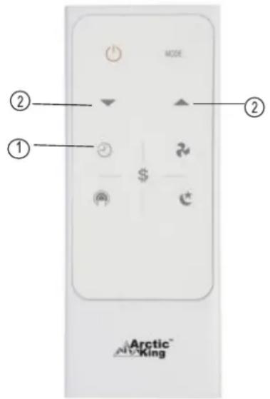
text_image
① ② ③ Arctic AirXingHow to Use the Buttons
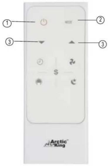
AUTO Operation
Ensure the unit is plugged in and power is available.
- Press the ON/OFF button to start the air conditioner.
- Press the MODE button to select AUTO.
- Press the TEMP UP/DOWN button to set the desired temperature. The temperature can be set within a range of 17^ C/62°F\~ 30^ C/86°F in 1^ C/1°F increments.
NOTE
- In AUTO mode, the air conditioner can automatically choose between the COOL, FAN, and HEAT mode by sensing the difference between the actual room temperature and the set temperature on the remote control.
- In AUTO mode, you cannot switch the fan speed. It has already been automatically controlled.
- If the AUTO mode is not comfortable for you, the desired mode can be selected manually.
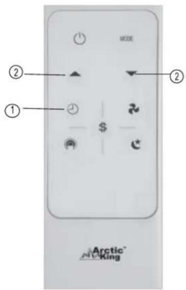
text_image
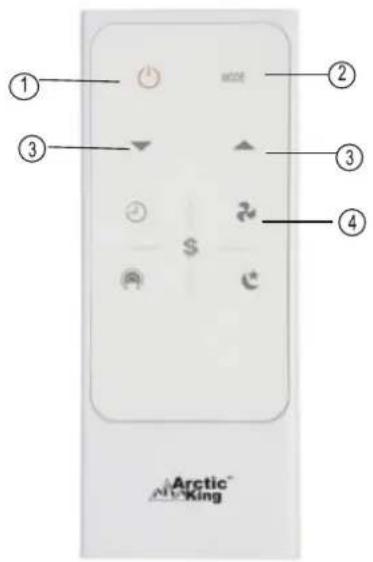
① ② ③ ④ Arctic KingCOOL/HEAT/FAN Operation
Ensure the unit is plugged in and power is available.
- Press the ON/OFF button to start the air conditioner.
- Press the MODE button to select the COOL or Fan mode.
- Press the TEMP UP/DOWN button to set the desired temperature. The temperature can be set within a range of 17^ C/62°F\~ 30^ C/86°F in 1^ C/1°F increments.
- Press the FAN button to select the fan speed in four steps: AUTO, LOW, MED or HIGH.
NOTE
In the Fan mode, the setting temperature is not displayed in the remote controller and you are not able to control the room temperature either. In this case, only step 1, 2 and 4 may be performed.
In FAN mode, the set temperature is not displayed in the remote control, the room temperature cannot be controlled. In this case only Steps 1, 2, and 4 may be performed.
Remote Control Operating Instructions
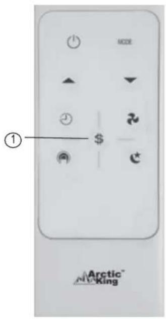
text_image
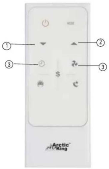
① ② ③ $ AirKingDRY Operation
Ensure the unit is plugged in and power is available.
- Press the ON/OFF button to start the air conditioner.
- Press the MODE button to select DRY.
- Press the TEMP UP/DOWN button to set the desired temperature. The temperature can be set within a range of 17^ C/62°F\~ 30^ C/86°F in 1^ C/1°F increments.
NOTE
In the DRY mode, you cannot switch the fan speed. It has already been automatically controlled.
text_image
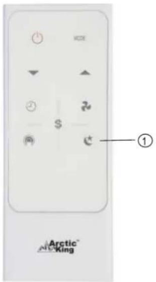
ACCE $ 2 ① Arctic® NC KingSleep Operation
- Press this button to active the SLEEP mode. This function is available under the most comfortable temperature for you.
- In this mode, the selected temperature will increase by 1 °C/ 2 °F 30 minutes after the mode is selected. The temperature will then increase by 1 °C/ 2 °F another after an additional 30 minutes. This new temperature will be maintained for 6 hours before it returns to the originally selected temperature. This ends the SLEEP mode and the unit will continue to operate as originally programmed.
- The SLEEP mode program can be cancelled when pressing the MODE, ON/OFF, FAN SPEED, or SLEEP button during operation.
Remote Control Operating Instructions
text_image
MODE ② ① Arctic AirKingTIMER Operation
Press the TIMER button to initiate the AUTO-START and AUTO-STOP setting program of the unit. The time can be set in a range of 0\~24 hours.
To set the AUTO-START/AUTO-STOP Time.
- Press the TIMER button. When TIMER ON indicator is displayed on the LED window of the air conditioner, it indicates that the AUTO-START setting program is initiated. When the TIMER OFF indicator is displayed on the LED window of the air conditioner, if indicates that the AUTO-STOP setting program is initiated.
- Press or hold the UP (▲) or DOWN(▼) to change the AUTO time in 0.5-hour increments, up to 10 hours, then in 1-hour increments up to 24 hours. The control will count down the remaining time until start/stop.
- The selected time will register in 5 seconds and the air conditioner will automatically revert back to display the previous temperature setting.
- Tuning the unit ON or OFF at any time will cancel the AUTO-START/AUTO-STOP function.
NOTE: To cancel the TIMER setting, press the TIMER button and press or hold the UP (▲) or DOWN (▼) until 0 hour is displayed on the air conditioner LED window.
Remote Control Operating Instructions
text_image
SCDE ② ① $ Arctic® NC KingCombined Timer
(setting both ON and OFF timers simultaneously)
AUTO-STOP → AUTO-START
(On → Stop → Start operation)
This feature is useful when you want to stop the air conditioner after going to bed and start it again when waking up in the morning or returning home.
Example:
To stop the air conditioner 2 hours after setting and start it again 10 hours after setting:
- Press the TIMER button until the TIMER OFF indicator is displayed on the air conditioner LED display.
- Use the UP/DOWN button to display "2.0" on the air conditioner LED display.
- Press the TIMER button again to display the TIMER OFF on the air conditioner LED display.
- Use the UP/DOWN button to display "10" on the air conditioner LED display.
- Wait for 5 seconds until the previous display reverts before to the LED
→ AUTO-STARTAUTO-STOP
(Off → Start → Stop operation)
This feature is useful when you want to start the air conditioner before waking up and stop it after leaving the house.
Example:
To start the air conditioner 5 hours after setting and stop it 8 hours after setting:
- Press the TIMER button until the TIMER ON indicator is displayed on the air conditioner LED display.
- Use the UP/DOWN button to display "5.0" on the air conditioner LED display.
- Press the TIMER button again to display the TIMER OFF on the air conditioner LED display.
- Use the UP/DOWN button to display "8.0" on the LED display of the unit.
- Wait for 5 seconds until the previous display reverts before the LED
Remote Control Operating Instructions
text_image
MODE ① $- Arctic™ KingENERGY SAVER Operation
In this mode, the fan will continue to run for 3 minutes after the compressor shuts off. The fan then cycles on for 2 minutes at 10-minute intervals until the room temperature is above the set temperature, at which time the compressor turns back on and cooling starts.
Remote Control Operating Instructions
NOTE:
-The design of is based on the typical model and might be slightly different from the actual one you purchased. In such case, the actual shape shall prevail.
-All functions described in these instructions apply to the available different models. If your model doesn't have a specific function, pressing the corresponding button will have no effect.
-If a function description between the "Remote Control Operating Instructions" and USER MANUAL is significantly different, the USER MANUAL description shall prevail.
-The device could comply with the local national regulations. In Canada, it should comply with CAN ICES-3(B)/NMB-3(B). In the USA, this device complies with Part 15 of the FCC Rules. Operation is subject to the following two conditions: (1) This device may not cause harmful interference and (2) this device must accept any interference received, including interference that may cause undesired operation.
-This equipment has been tested and found to comply with the limits for a Class B digital device, pursuant to Part 15 of the FCC Rules. These limits are designed to provide reasonable protection against harmful interference in a residential installation. This equipment generates, uses, and can radiate radio frequency energy and, if not installed and used in accordance with the instructions, may cause harmful interference to radio communications. However, there is no guarantee that interference will not occur in a particular installation. If this equipment does cause harmful interference to radio or television reception, which can be determined by turning the equipment off and on, the user is encouraged to try to correct the interference by one or more of the following measures:
•Reorient or relocate the receiving antenna.
- Increase the separation between the equipment and receiver.
- Connect the equipment into an outlet on a circuit different from that to which the receiver is connected.
- Consult the dealer or an experienced radio/TV technician for help. Changes or modifications not approved by the party responsible for compliance could void the suer's authority to operate the equipment.
These products have been made to quality standards and are guaranteed for domestic use against manufacturing faults.
One (1) year full warranty from original purchase date and limited 2nd through 5th year sealed system warranty if used for normal domestic purposes.
This warranty does not affect your statutory rights. In case of any malfunction of your product (failure, missing part, etc.), please contact one of our service technicians at our toll-free service line at 1-866-646-4332 from 8 AM to 6 PM EST, Monday to Friday, and 8 AM to 4 PM EST, Saturday. Midea reserves the right to repair or replace the defective product, at its discretion.
Any warranty is invalid if the product has been overloaded or subject to neglect, improper use or an attempted repair other than by an authorized agent. Heavy-duty or daily professional/commercial usage are not guaranteed. Due to continuous product improvement, we reserve the right to change product specifications without prior notice.
For instructions on how to properly drain Freon, please contact our customer service at 1-866-646-4332. Thank you.
Arctic™ King
No. d'article
817036
Réf.
21615016
Modèle
NO.
MWDUL-10CRN1-BCJ4
natural_image
Line drawing of a server unit with ventilation grilles and control panel (no text or symbols)Our Customer service staff is available to help you. For any problem with your purchase, or to receive further information about this product, please call our toll-free number.
SAVE THIS MANUAL
Keep this manual and the original sales invoice in a safe, dry place for future reference.
natural_image
Technical line drawing of a front panel with internal grid layout and control buttons (no text or symbols)text_image
Technical diagram of an electronic device with numbered components for identification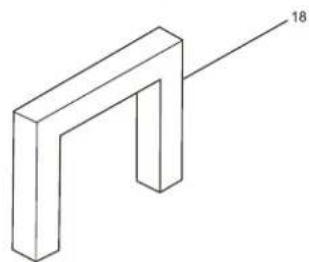
natural_image
Isometric line drawing of a 3D L-shaped structure with no text or symbols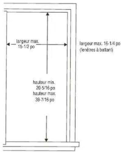
natural_image
Technical line drawing of a mechanical assembly with a pulley and circular inset view (no text or symbols)Support de sécurité