
MAP06R1BWT - Air Conditioning MIDEA - Free user manual and instructions
Find the device manual for free MAP06R1BWT MIDEA in PDF.

| Product type | Portable single-duct air conditioner |
| Model | MAP06R1BWT |
| Brand | Midea |
| Cooling capacity (SACC) | 6000 BTU/h (approx) |
| Refrigerant | R32 (flammable) |
| Power supply | 115 V ~ 60 Hz, grounded plug |
| Dimensions (approx.) | H 70 cm × W 35 cm × D 45 cm |
| Weight (approx.) | 25 kg |
| Operating modes | Cool, Fan, Dehumidify, Heat (heat pump) |
| Fan speeds | 2-3 speeds (Auto, Low, High) |
| Remote control | Yes, with LCD display |
| Connectivity | Built-in Wi-Fi (SmartHome app) |
| Timer | Programmable on/off (0-24 h) |
| Sleep function | Yes, gradual temperature adjustment |
| Ionizer function | Yes (FRESH mode) |
| Maintenance | Clean filter every 2 weeks |
| Water drainage | Manual drain in dry mode or P1 alarm |
| Exhaust hose length | 1.5 m (extendable to 3 m with extension) |
| Installation | Sliding window or wall hole (kit included) |
| Safety | Refrigerant leak protection, current detection, auto restart |
| Warranty | 1 year full, 5 years on sealed system |
Frequently Asked Questions - MAP06R1BWT MIDEA
User questions about MAP06R1BWT MIDEA
0 question about this device. Answer the ones you know or ask your own.
Ask a new question about this device
Download the instructions for your Air Conditioning in PDF format for free! Find your manual MAP06R1BWT - MIDEA and take your electronic device back in hand. On this page are published all the documents necessary for the use of your device. MAP06R1BWT by MIDEA.
USER MANUAL MAP06R1BWT MIDEA
natural_image
Technical line drawing of a rectangular device with internal grating and mounting feet (no text or symbols)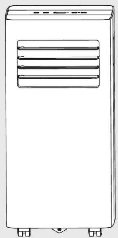
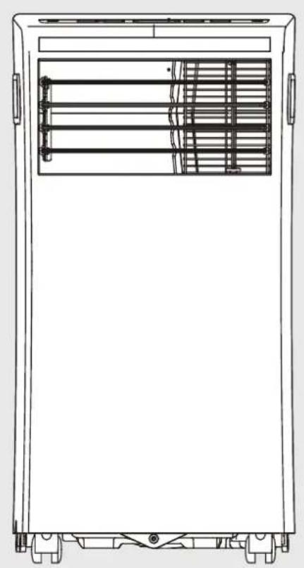
natural_image
Line drawing of a portable air conditioner unit with ventilation slots and mounting feet (no text or symbols)
PORTABLE AIR CONDITIONER


SmartHome
Download the app & activate product
OWNER'S MANUAL
Model NO. MAP06R1BWT
Model NO. MAP08R1CWT
Our customer service staff is available to help you. For any problem with your purchase, or to receive further information about this product, please call our toll-free number.
SAVE THIS MANUAL
Keep this manual and the original sales invoice in a safe, dry place for future reference.
Read Safety Precautions Before Operation and Installation
To prevent death or injury to the user or other people and property damage, the following instructions must be followed. Incorrect operation due to ignoring of instructions may cause death, harm or damage.
| WARNING | This symbol indicates the possibility of personnel injury or loss of life. |
| CAUTION | This symbol indicates the possibility of property damage or serious consequences. |

WARNING
- Installation must be performed according to the installation instructions. Improper installation can cause water leakage, electrical shock, or fire.
- Use only the included accessories and parts, and specified tools for the installation. Using nonstandard parts can cause water leakage, electrical shock, fire, and injury or property damage.
- Make sure that the outlet you are using is grounded and has the appropriate voltage.
The power cord is equipped with a three-prong grounding plug to protect against shock.
Voltage information can be found on the nameplate of the unit. - Your unit must be used in a properly grounded wall receptacle. If the wall receptacle you intend to use is not adequately grounded or protected by a time delay fuse or circuit breaker (the fuse or circuit breaker needed is determined by the maximum current of the unit. The maximum current is indicated on the nameplate located on unit), have a qualified electrician install the proper receptacle.
• Install the unit on a flat, sturdy surface. Failure to do so could result in damage or excessive noise and vibration. - The unit must be kept free from obstruction to ensure proper function and to mitigate safety hazards.
- Do not modify the length of the power cord or use an extension cord to power the unit.
- Do not share a single outlet with other electrical appliances. Improper power supply can cause fire or electrical shock.
- Do not install your air conditioner in a wet room such as a bathroom or laundry room. Too much exposure to water can cause electrical components to short circuit.
- Do not install the unit in a location that may be exposed to combustible gas, as this could cause fire.
- The unit has wheels to facilitate moving. Make sure not to use the wheels on thick carpet or to roll over objects, as these could cause tipping.
- Do not operate a unit that it has been dropped or damaged.
- The appliance with electric heater shall have at least 1 meter space to the combustible materials.
- Do not touch the unit with wet or damp hands or when barefoot.
- If the air conditioner is knocked over during use, turn off the unit and unplug it from the main power supply immediately. Visually inspect the unit to ensure there is no damage. If you suspect the unit has been damaged, contact a technician or customer service for assistance.

WARNING
- In a thunderstorm, the power must be cut off to avoid damage to the machine due to lightning.
- Your air conditioner should be used in such a way that it is protected from moisture. e.g. condensation, splashed water, etc. Do not place or store your air conditioner where it can fall or be pulled into water or any other liquid. Unplug immediately if it occurs.
- All wiring must be performed strictly in accordance with the wiring diagram located inside of the unit.
- The unit's circuit board(PCB) is designed with a fuse to provide overcurrent protection. The specifications of the fuse are printed on the circuit board, such as: T 3.15A/250V, etc.
- When the water drainage function is not in use, keep the upper and the lower drain plug firmly to the unit to get rid of choking. When the drain plug is not in use, keep it carefully to prevent children from choking.

CAUTION
- This appliance is not intended for use by persons (including childern) with reduced physical, sensory or mental capabilities or lack of experience and knowledge, unless they have been given supervision or instruction concerning use of the appliance by a person responsible for their safety. Children should be supervised to ensure that they do not play with the appliance. Children must be supervised around the unit at all times.(be applicable for other countries except the European Countries)
- If the supply cord is damaged, it must be replaced by the manufacturer, its service agent or similarly qualified persons in order to avoid a hazard.
- Prior to cleaning or other maintenance, the appliance must be disconnected from the supply mains.
- Do not remove any fixed covers. Never use this appliance if it is not working properly, or if it has been dropped or damaged.
- Do not run cord under carpeting. Do not cover cord with throw rugs, runners, or similar coverings. Do not route cord under furniture or appliances. Arrange cord away from traffic area and where it will not be tripped over.
- Do not operate unit with a damaged cord, plug, power fuse or circuit breaker. Discard unit or return to an authorized service facility for examination and/or repair.
- To reduce the risk of fire or electric shock, do not use this fan with any solid-state speed control device.
- The appliance shall be installed in accordance with national wiring regulations.
- Contact the authorised service technician for repair or maintenance of this unit.
- Contact the authorised installer for installation of this unit.
- Do not cover or obstruct the inlet or outlet grilles.
- Do not use this product for functions other than those described in this instruction manual.
- Before cleaning, turn off the power and unplug the unit.
- Disconnect the power if strange sounds, smell, or smoke comes from it.
- Do not press the buttons on the control panel with anything other than your fingers.
- Do not remove any fixed covers. Never use this appliance if it is not working properly, or if it has been dropped or damaged.
- Do not operate or stop the unit by inserting or pulling out the power cord plug.

CAUTION
- Do not use hazardous chemicals to clean or come into contact with the unit. Do not use the unit in the presence of inflammable substances or vapour such as alcohol, insecticides, petrol, etc.
- Always transport your air conditioner in a vertical position and stand on a stable, level surface during use.
- Always contact a qualified person to carry out repairs. If the damaged power supply cord must be replaced with a new power supply cord obtained from the product manufacturer and not repaired.
- Hold the plug by the head of the power plug when taking it out.
- Turn off the product when not in use.
Electronic Work

WARNING:
BEFORE PERFORMING ANY ELECTRICAL OR WIRING WORK, TURN OFF THE MAIN POWER TO THE SYSTEM.
flowchart
graph TD
    A["DISPLAY"] --> B["MAIN CONTROL"]
    B --> C["POWER SUPPLY CORD"]
NOTE: The cographs are for explanation purpose only. Your machine may be slightly different. The actual shape shall prevail.

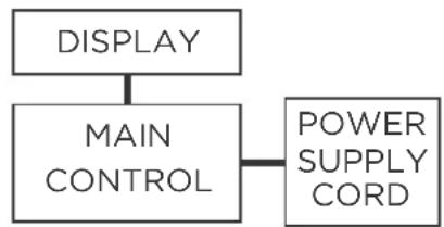
WARNING for Using R32 Refrigerant
- Do not use means to accelerate the defrosting process or to clean, other than those recommended by the manufacturer.
- The appliance shall be stored in a room without continuously operating ignition sources (for example: open flames, an operating gas appliance or an operating electric heater).
- Do not pierce or burn.
- Be aware that the refrigerants may not contain an odour.
- Appliance should be installed, operated and stored in a room with a floor area according to the amount of refrigerant to be charged. For specific information on the type of gas and the amount, please refer to the relevant label on the unit itself. When there are differences between the lable and the manual on the Min. room area description, the description on label shall prevail.
- Appliance shall be installed, operated and stored in a room with a floor area larger than 4m^2 . Appliance shall not be installed in an unvertilated space, if that space is smaller than 4m^2 .
- No any open fire or device like switch which may generate spark/arcing shall be around appliance to avoid causing ignition of the flammable refrigerant used. Please follow the instructions carefully when storing or maintaining the appliance to prevent mechanical damage from occurring.
CAUTION:
Risk of fire
flammable materials
Explanation of symbols displayed on the unit
 | CAUTION | This symbol shows that the operation manual should be read carefully. |
 | CAUTION | This symbol shows that a service personnel should be handling this equipment with reference to the installation manual. |
 | CAUTION | This symbol shows that information is available such as the operating manual or installation manual. |

WARNING
- Servicing shall only be performed as recommended by the equipment manufacturer. Maintenance and repair requiring the assistance of other skilled personnel shall be carried out under the supervision of the person competent in the use of flammable refrigerants.
- DO NOT modify the length of the power cord or use an extension cord to power the unit.
- DO NOT share a single outlet with other electrical appliances. Improper power supply can cause fire or electrical shock.
- Please follow the instruction carefully to handle, install, clear, service the appliance to avoid any damage or hazard.
- When maintaining or disposing the appliance, the refrigerant shall be recovered properly, shall not discharge to air directly.
- Compliance with national gas regulations shall be observed.
- Keep ventilation openings clear of obstruction.
- The appliance shall be stored so as to prevent mechanical damage from occurring.
- A warning that the appliance shall be stored in a well-ventilated area where the room size corresponds to the room area as specified for operation.
- Any person who is involved with working on or breaking into a refrigerant circuit should hold a current valid certificate from an industry-accredited assessment authority, which authorises their competence to handle refrigerants safely in accordance with an industry recognised assessment specification. All training shall follow the ANNEX HH requirements of UL 60335-2-40.
Examples for such working procedures are:
- breaking into the refrigerating circuit;
- opening of sealed components;
- opening of ventilated enclosures.
1. Transport of equipment containing flammable refrigerants
See transport regulations.
2. Marking of equipment using signs
See local regulations.
3. Disposal of equipment using flammable refrigerants
See national regulations.
4. Storage of equipment/appliances
The storage of equipment should be in accordance with the manufacturer's instructions.
5.Storage of packed (unsold) equipment
Storage package protection should be constructed such that mechanical damage to the equipment inside the package will not cause a leak of the refrigerant charge. The maximum number of pieces of equipment permitted to be stored together will be determined by local regulations.
6. Information on servicing
1) Checks to the area
Prior to beginning work on systems containing flammable refrigerants, safety checks are necessary to ensure that the risk of ignition is minimised. For repair to the refrigerating system, the following precautions shall be complied with prior to conducting work on the system.
2) Work procedure
Work shall be undertaken under a controlled procedure so as to minimise the risk of a flammable gas or vapour being present while the work is being performed.
3) General work area
All maintenance staff and others working in the local area shall be instructed on the nature of work being carried out. Work in confined spaces shall be avoided. The area around the workspace shall be sectioned off. Ensure that the conditions within the area have been made safe by control of flammable material.
4) Checking for presence of refrigerant
The area shall be checked with an appropriate refrigerating detector prior to and during work, to ensure the technician is aware of potentially flammable atmospheres. Ensure that the leak detection equipment being used is suitable for use with flammable refrigerants, i.e. non-sparking, adequately sealed or intrinsically safe.
5) Presence of fire extinguisher
If any hot work is to be conducted on the refrigeration equipment or any associated parts, appropriate fire extinguishing equipment shall be available to hand. Have a dry powder or CO2 fire extinguisher adjacent to the charging area.
6) No ignition sources
No person carrying out work in relation to a refrigerating system which involves exposing any pipe work that contains or has contained flammable refrigerant shall use any sources of ignition in such a manner that it may lead to the risk of fire or explosion. All possible ignition sources, including cigarette smoking, should be kept sufficiently far away from the site of installation, repairing, removing and disposal, during which flammable refrigerant can possibly be released to the surrounding space. Prior to work taking place, the area around the equipment is to be surveyed to make sure that there are no flammable hazards or ignition risks. No Smoking signs shall be displayed.
7) ventilated area
Ensure that the area is in the open or that it is adequately ventilated before breaking into the system or conducting any hot work. A degree of ventilation shall continue during the period that the work is carried out. The ventilation should safely disperse any released refrigerant and preferably expel it externally into the atmosphere.
8) Checks to the refrigerating equipment
Where electrical components are being changed, they shall be fit for the purpose and to the correct specifications. At all times the manufacturer's maintenance and service guidelines shall be followed. If in doubt consult the manufacturer's technical department for assistance. The following checks shall be applied to installations using flammable refrigerants: the actual refrigerant charge is in accordance with the room size within which the refrigerant containing parts are installed; the ventilation machinery and outlets are operating adequately and are not obstructed; if an indirect refrigerating circuit is being used, the secondary circuit shall be checked for the presence of refrigerant; marking to the equipment continues to be visible and legible.
Markings and signs that are illegible shall be corrected; and refrigerating pipe or components are installed in a position where they are unlikely to be exposed to any substance which may corrode refrigerant containing components, unless the components are constructed of materials which are inherently resistant to being corroded or are suitably protected against being so corroded.
9) Checks to electrical devices
Repair and maintenance to electrical components shall include initial safety checks and component inspection procedures. If a fault exists that could compromise safety, then no electrical supply shall be connected to the circuit until it is satisfactorily dealt with. If the fault cannot be corrected immediately but it is necessary to continue operation, an adequate temporary solution shall be used. This shall be reported to the owner of the equipment so all parties are advised. Initial safety checks shall include: That capacitors are discharged: this shall be done in a safe manner to avoid possibility of sparking; that there no live electrical components and wiring are exposed while charging, recovering or purging the system; that there is continuity of earth bonding.
7.Sealed electrical components shall be replaced.
1) During repairs to sealed components, all electrical supplies shall be disconnected from the equipment being worked upon prior to any removal of sealed covers, etc. If it is absolutely necessary to have an electrical supply to equipment during servicing, then a permanently operating form of leak detection shall be located at the most critical point to warn of a potentially hazardous situation.
2) Particular attention shall be paid to the following to ensure that by working on electrical components, the casing is not altered in such a way that the level of protection is affected. Check for damage to cables, excessive number of connections, terminals not made to original specification, damage to seals, incorrect fitting of glands, etc. Ensure that apparatus is mounted securely. Ensure that seals or sealing materials have not degraded such that they no longer serve the purpose of preventing the ingress of flammable atmospheres. Replacement parts shall be in accordance with the manufacturer's specifications.
NOTE: The use of silicon sealant may inhibit the effectiveness of some types of leak detection equipment. Intrinsically safe components do not have to be isolated prior to working on them.
8. Intrinsically safe components must be replaced.
Do not apply any permanent inductive or capacitance loads to the circuit without ensuring that this will not exceed the permissible voltage and current permitted for the equipment in use. Intrinsically safe components are the only types that can be worked on while live in the presence of a flammable atmosphere. The test apparatus shall be at the correct rating. Replace components only with parts specified by the manufacturer. Other parts may result in the ignition of refrigerant in the atmosphere from a leak.
9. Cabling
Check that cabling will not be subject to wear, corrosion, excessive pressure, vibration, sharp edges or any other adverse environmental effects. The check shall also take into account the effects of aging or continual vibration from sources such as compressors or fans.
10. Detection of flammable refrigerants
Under no circumstances shall potential sources of ignition be used in the searching for or detection of refrigerant leaks. A halide torch (or any other detector using a naked flame) shall not be used.
The following leak detection methods are deemed acceptable for systems containing flammable refrigerants. Electronic leak detectors shall be used to detect flammable refrigerants, but the sensitivity may not be adequate, or may need re-calibration. (Detection equipment shall be calibrated in a refrigerant-free area.) Ensure that the detector is not a potential source of ignition and is suitable for the refrigerant used. Leak detection equipment shall be set at a percentage of the LFL of the refrigerant and shall be calibrated to the refrigerant employed and the appropriate percentage of gas (25 % maximum) is confirmed. Leak detection fluids are suitable for use with most refrigerants but the use of detergents containing chlorine shall be avoided as the chlorine may react with the refrigerant and corrode the copper pipe-work. If a leak is suspected, all naked flames shall be removed/ extinguished. If a leakage of refrigerant is found which requires brazing, all of the refrigerant shall be recovered from the system, or isolated (by means of shut off valves) in a part of the system remote from the leak.
Removal of refrigerant shall be according to Removal and evacuation.
11. Removal and evacuation
When breaking into the refrigerant circuit to make repairs—or for any other purpose
- conventional procedures shall be used. However, for flammable refrigerants it is important that best practice be followed, since flammability is a consideration.
The following procedure shall be adhered to:
-Safely remove refrigerant following local and national regulations;
-Evacuate;
-Purge the circuit with inert gas (optional for A2L);
-Evacuate (optional for A2L);
-continuously flush or purge with inert gas when using flame to open circuit; and -open the circuit.
The refrigerant charge shall be recovered into the correct recovery cylinders if venting is not allowed by local and national codes. For appliances containing flammable refrigerants, the system shall be purged with oxygen-free n flammable refrigerants. This process might compressed air or oxygen shall not be used for purging refrigerant systems.
For appliances containing flammable refrigerants, refrigerants purging shall be achieved by breaking the vacuum in the system with oxygen-free nitrogen and continuing to fill until the working pressure is achieved, then venting to atmosphere, and finally pulling down to a vacuum (optional for A2L). This process shall be repeated until no refrigerant is within the system (optional for A2L). When the final oxygen-free nitrogen charge is used, the system shall be vented down to atmospheric pressure to enable work to take place. The outlet for the vacuum pump shall not be close to any potential ignition sources, and ventilation shall be available.
12. Charging procedures
In addition to conventional charging procedures, the following requirements shall be followed. Ensure that contamination of different refrigerants does not occur when using charging equipment. Hoses or lines shall be as short as possible to minimise the amount of refrigerant contained in them. Cylinders shall be kept in an appropriate position according to the instructions. Ensure that the refrigeration system is earthed prior to charging the system with refrigerant. Label the system when charging is complete (if not already). Extreme care shall be taken not to overfill the refrigeration system. Prior to recharging the system it shall be pressure tested with OFN. The system shall be leak tested on completion of charging but prior to commissioning. A follow up leak test shall be carried out prior to leaving the site.
13.Decommissioning
Before carrying out this procedure, it is essential that the technician is completely familiar with the equipment and all its detail. It is recommended good practice that all refrigerants are recovered safely.
Prior to the task being carried out, an oil and refrigerant sample shall be taken in case analysis is required prior to re-use of reclaimed refrigerant. It is essential that electrical power is available before the task is commenced.
a) Become familiar with the equipment and its operation.
b) Isolate system electrically.
c) Before attempting the procedure ensure that: Mechanical handling equipment is available, if required, for handling refrigerant cylinders; all personal protective equipment is available and being used correctly; the recovery process is supervised at all times by a competent person; recovery equipment and cylinders conform to the appropriate standards.
d) Pump down refrigerant system, if possible.
e) If a vacuum is not possible, make a manifold so that refrigerant can be removed from various parts of the system.
f) Make sure that cylinder is situated on the scales before recovery takes place.
g) Start the recovery machine and operate in accordance with manufacturer's instructions.
h) Do not overfill cylinders. (No more than 80 % volume liquid charge).
i) Do not exceed the maximum working pressure of the cylinder, even temporarily.
j) When the cylinders have been filled correctly and the process completed, make sure that the cylinders and the equipment are removed from site promptly and all isolation valves on the equipment are closed off.
k) Recovered refrigerant shall not be charged into another refrigeration system unless it has been cleaned and checked.
14. Labelling
Equipment shall be labelled stating that it has been de-commissioned and emptied of refrigerant. The label shall be dated and signed. Ensure that there are labels on the equipment stating the equipment contains flammable refrigerant.
15.Recovery
When removing refrigerant from a system, either for servicing or decommissioning, it is recommended good practice that all refrigerants are removed safely. When transferring refrigerant into cylinders, ensure that only appropriate refrigerant recovery cylinders are employed. Ensure that the correct number of cylinders for holding the total system charge is available. All cylinders to be used are designated for the recovered refrigerant and labelled for that refrigerant (i.e. special cylinders for the recovery of refrigerant). Cylinders shall be complete with pressure relief valve and associated shut-off valves in good working order. Empty recovery cylinders are evacuated and, if possible, cooled before recovery occurs. The recovery equipment shall be in good working order with a set of instructions concerning the equipment that is at hand and shall be suitable for the recovery of the flammable refrigerant. If in doubt, the manufacturer should be consulted. In addition, a set of calibrated weighing scales shall be available and in good working order. Hoses shall be complete with leak-free disconnect couplings and in good condition.
The recovered refrigerant shall be processed according to local legislation in the correct recovery cylinder, and the relevant waste transfer note arranged. Do not mix refrigerants in recovery units and especially not in cylinders. If compressors or compressor oils are to be removed, ensure that they have been evacuated to an acceptable level to make certain that flammable refrigerant does not remain within the lubricant. The compressor body shall not be heated by an open flame or other ignition sources to accelerate this process. When oil is drained from a system, it shall be carried out safely.
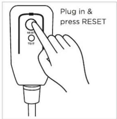
Operation of Current Device
The power supply cord contains a current measuring device that detects damage to the power cord. Test your power supply cord as follows:
- Plug in the air conditioner.
- The power supply cord will have TWO buttons on the plug head. Press the TEST button. You will notice a click as the RESET button pops out.
- Press the RESET Button. You will notice a click as the button engages.
- The power supply cord is now supplying electricity to the unit. (On some products this is also indicated by a light on the plug head.)

NOTE
The power supply cord with this air conditioner contains a current detection device designed to reduce the risk of fire.
In the event that the power supply cord is damaged, it can not be repaired. It must be replaced with a cord from the manufacturer.

NOTE
• Do not use this device to turn the unit on or off.
• Always make sure the RESET button is pushed in for correct operation.
- The power supply cord must be replaced if it fails to reset when either the TEST button is pushed, or it can not be reset. Please contact Customer Service.
Grounding type wall receptacle
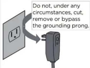
Power supply cord with 3-prong grounding plug and current detection device.
INSTALLATION INSTRUCTIONS
Preparation
NOTE:
All the illustrations in the manual are for explanation purpose only. Your machine may be slightly different.
The actual shape shall prevail. The unit can be controlled by the unit control panel alone or with the remote controller. This manual does not include Remote Controller Operations, see the <
DESIGN NOTICE
In order to ensure the optimal performance of our products, the design specifications of the unit and remote control are subject to change without prior notice.
Ambient Temperature Range For Unit Operating
| MODE Temperature Range MODE Temperature Range | |||
| Cool | 17-35°C (62-95°F) | Heat(pump heat mode) | 5-30°C (41-86°F) |
| Dry | Heat(electrical heat mode) | 13-35°C(056-988°F) | |
Exhaust Hose Installation
The exhaust hose and adaptor must be installed or removed in accordance with the usage mode. For COOL,HEAT(heat pump type) or AUTO mode must be installed exhaust hose. For FAN, DRY or HEAT(electrical heat type) mode must be removed exhaust hose.
Choosing The Right Location
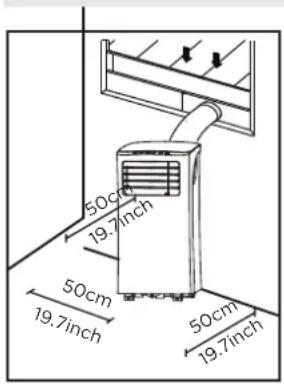
Your installation location should meet the following requirements:
- Make sure that you install your unit on an even surface to minimize noise and vibration.
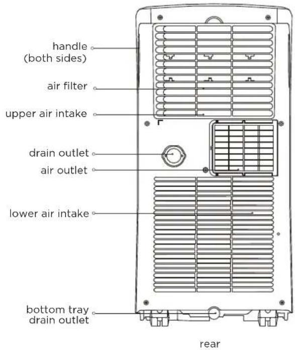
- The unit must be installed near a grounded plug, and the Collection Tray Drain (found on the back of the unit) must be accessible.
- The unit should be located at least 50cm (19.7") from the nearest wall to ensure proper air conditioning. The horizontal louver blade should be at least 50cm (19.7") away from obstacles.
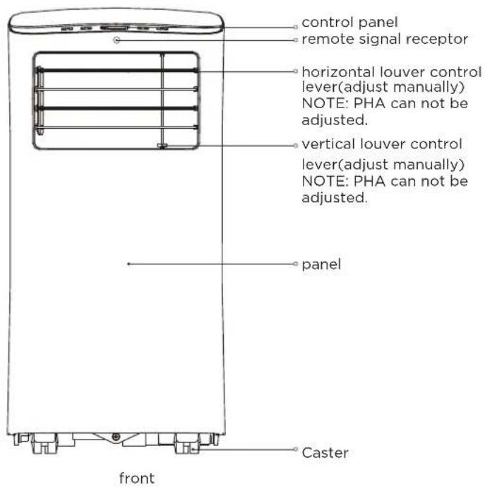
- DO NOT cover the Intakes, Outlets or Remote Signal Receptor of the unit, as this could cause damage to the unit.
Recommend Installation
Energy Rating Information
The energy rating and noise information for this unit is based on the standard installation using an un-extended exhaust duct without window slider adaptor (as shown in the Installation section of this manual). At the same time, the unit must be operate on the COOL MODE and HIGH FAN SPEED by remote controller.
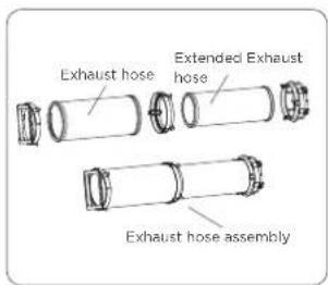
The unit with 3 meters extended exhaust duct is running by using 2 exhaust ducts(Diameter:150mm, Length:1.5m + Diameter: 130mm, Length: 1.5m). The Energy rating and noise information for unit with 3 meters extended exhaust duct is not assessed.(For some models)
NOTE:
We recommend that operating the unit at room temperature below 35^ C. Since there is a risk that the unit with 3 meters extended exhaust duct would not work at room temperature above 35^ C under some extreme conditions, such as the lower air intake be blocked for 50%.
How to Stay Cool with a New Portable Air Conditioner(For the models comply with the requirements of Department Of Energy in US)
Because of a new federal test procedure for Portable Air Conditioners, you may notice that the cooling capacity claims on portable air conditioner packaging are significantly lower than that of models produced prior to 2017.
This is due to changes in the test procedure, not to the portable air conditioners themselves.
What should I look for first when purchasing a portable air conditioner?
The right air conditioner helps you cool a room efficiently. An undersized unit won't cool adequately while one that's too large will not remove enough humidity, leaving the air feeling damp. To find the proper air conditioner, determine the square footage of the room you want to cool by multiplying the room length by its width. You also need to know the air conditioner's BTU (British Thermal Unit) rating, which indicates the amount of heat it can remove from a room. A higher number means more cooling power for a larger room. (Be sure you are comparing only newer models to each other- older models may appear to have a higher capacity, but are actually the same). Be sure to "size up" if your portable air conditioner will be placed in a very sunny room, in a kitchen, or in a room with high ceilings. After you've found the right cooling capacity or your room, you can look at other features.
Why is the cooling capacity lower on newer models than on older units?
Federal regulations require manufacturers to calculate cooling capacity based on a specific test procedure, which was changed just this year. Models manufactured before 2017 were tested under a different procedure and cooling capacity is measured differently than in prior years' models. So, while the BTUs may be lower, the actual cooling capacity of the air conditioners has not changed.
What is SACC?
SACC is the representative value of Seasonally Adjusted Cooling Capacity, in Btu/h, as determined in accordance with the DOE test procedure at title 10 Code of Federal Regulations (CFR) 430, subpart B, appendix CC and applicable sampling plans.
Tools Needed
- Medium Philips screwdriver; -Tape measure or ruler; -Knife or scissors;
- Saw (optional, to shorten window adaptor for narrow windows)
Accessories
NOTE: Items with (*) are on some models. Slight variations in design may occur.
North America
| Shape | Name of Accessories | Qty. | Shape | Name of Accessories | Qty. |
| Unit Adaptor | 1 pc | Security Bracket and 2 Screws | 1 set | ||
| Exhaust Hose | 1 pc | Drain Hose | 1 pc | ||
| Window Slider Adaptor | 1 pc(on some models) | Power Cord Buckle | 1 pc(on some models) | ||
| Window Slider A | 1 pc | Bolt | 1 pc/2 pc(*) | ||
| Window Slider B | 1 pc | Remote Controller and Battery(only for remote control models) | 1 set(*) | ||
| Window Slider C | 1 pc(*) | Drain Hose Adaptor(only for heat pump mode) | 1 pc(*) | ||
| Foam Seal A (Adhesive) | 2 pc/4 pc(*) | Exhaust Hose Adaptor | 1 pc(*)(on some models) | ||
| Foam Seal B (Adhesive) | 2 pc | Extended Exhaust Hose | 1 pc(*)(on some models) | ||
| Foam Seal C (Non-adhesive) | 1 pc/2 pc(*) | Air exhaust passage | 1 pc(*) | ||
| Window Sliders | 1 set(*) |
Other Regions
| Shape | Name of Accessories | Qty. | Shape | Name of Accessories | Qty. |
1 pc 1 set(*)Un  | Security Bracket and 2 Screws | ||||
| 1 pc 1 pcExhaust Hose Drain Hose | |||||
| Window Slider Adaptor Power CordBuck (on some models) | 1 pc(*) 1 pc  | (on some models) | |||
| 1 pc(*) Window Slider A Bolt | 1 pc(*) | ||||
 | Remote Controller and Battery(only for remote control models) | 1 set(*)1 pc(*) Window S | |||
| 2 pc(*)Foam Seal A (Adhesive) | Wall Exhaust Adaptor A(Only for wall installation models) | 1 pc(*) | |||
| 2 pc(*)Foam [SXC3] | Wall Exhaust Adaptor B(with cap)(Only for wall installation models) | 1 pc(*) | |||
| Foam Seal C (Non-adhesive) | 1 pc(*) |  | Screw and anchor(only for wall installation models) | 4 set(*) | |
| Drain Hose Adaptor(only for heat pump mode) | 1 pc(*) | Extended Exhaust Hose | 1 pc(*) (on some models) | ||
| Exhaust Hose Adaptor | 1 pc(*) (on some models) |  | 1 pc(*)Air exhaust passag | ||
| 1 set(*) Window Sliders | |||||
Window Installation Kit
Type window installation:
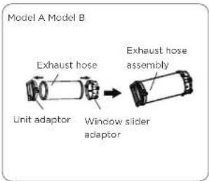
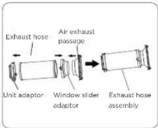
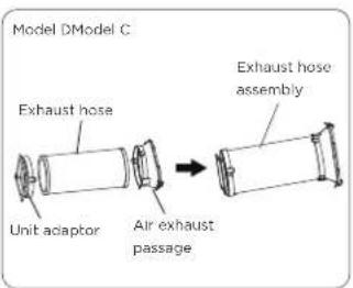
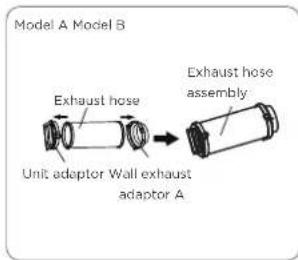
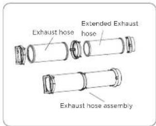
Step One: Preparing the Exhaust Hose assembly
Press the exhaust hose(or extended exhaust hose) into the window slider adaptor(or wall exhaust adaptor) and unit adaptor, clamp automatically by elastic buckles of the adaptors.
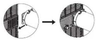
Type wall installation:
natural_image
Diagram showing a mechanical joint before and after assembly, with no visible text or symbols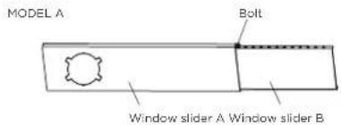
flowchart
graph TD
    A["Window Sliders"] --> B["Before assembly"]
    B --> C["Output"]
Step Two: Install the Exhaust hose assembly to the unit
Push the Exhaust hose into the airoutlet opening of the unit along the arrow direction.
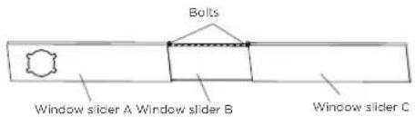
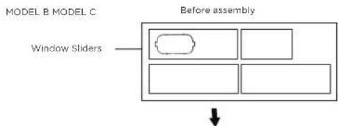
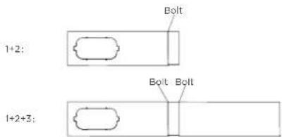
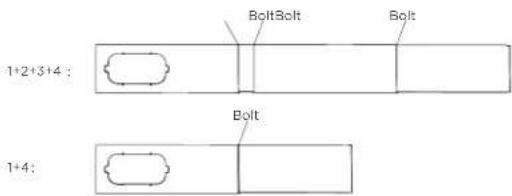
Step Three: Preparing the Adjustable Window Slider
- Choose the window sliders according the size of your window. Sometimes, it needs to be cut short to meet the window size, please take extra care to cut it properly.
- Use bolts to fasten the window sliders once they are adjusted to the Proper length.
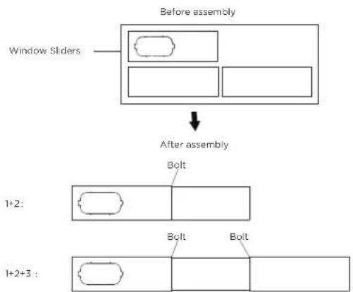
flowchart
graph TD
    A["Window Sliders"] --> B["Before assembly"]
    B --> C["After assembly"]
    C --> D["1+2:"]
    D --> E["Bolt"]
    D --> F["Bolt"]
    D --> G["Bolt"]
    H["1+2+3:"] --> I["Bolt"]
    I --> J["Bolt"]
Installation
NOTE: Once the Exhaust Hose assembly and Adjustable Window Slider are prepared, choose from one of the following two installation methods.
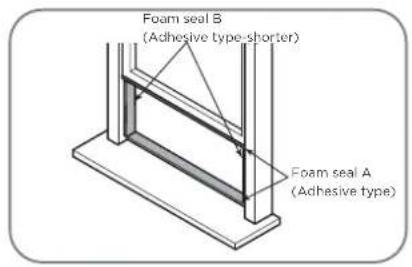
Type 1: Hung Window or Sliding Window Installation(For some models)
Or
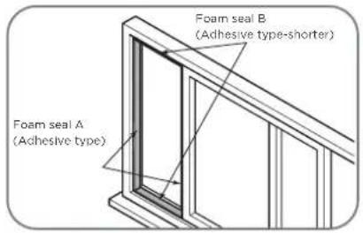
- Cut the adhesive foam seal A and B strips to the proper lengths, and attach them to the window sash and frame as shown.
Or
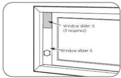
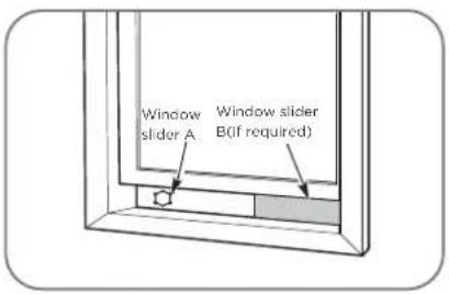
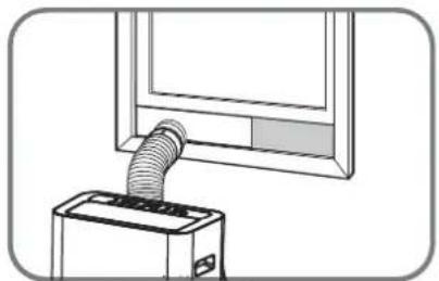
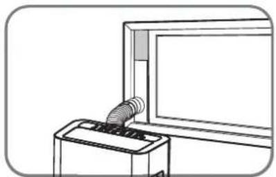
- Insert the window slider assembly into the window opening.
Or
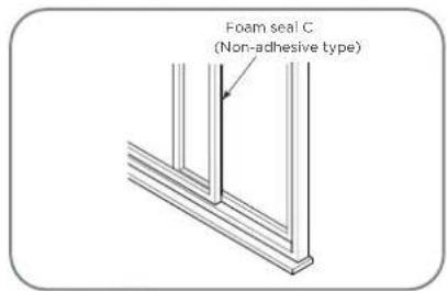
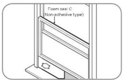
- Cut the non-adhesive foam seal C strip to match the width(or height) of the window. Insert the seal between the glass and the window frame to prevent air and insects from getting into the room.
Or
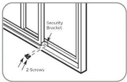
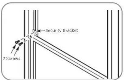
- If desired, install the security bracket with 2 screws as shown.
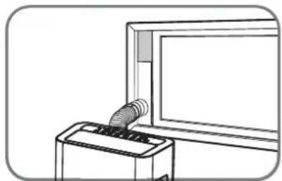
natural_image
Line drawing of a vacuum cleaner emitting a hose, mounted on a device (no text or symbols)Or
natural_image
Line drawing of a printer emitting a coiled cable into a screen (no text or symbols)- Insert the window slider adaptor into the hole of the window slider.
Type 2: Wall Installation(For some models)
- Cut a 125mm (4.9inch) hole into the wall for the Wall Exhaust Adaptor B.
- Secure the Wall Exhaust Adaptor B to the wall using the four Anchors and Screws provided in the kit.
- Connect the Exhaust Hose Assembly(with Wall Exhaust Adaptor A) to the Wall Exhaust Adaptor B.
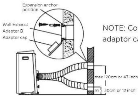
NOTE: Cover the hole using the adaptor cap when not in use.
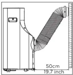
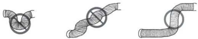
NOTE: To ensure proper function, DO NOT overextend or bend the hose. Make sure that there is no obstacle around the air outlet of the exhaust hose (in the range of 500mm) in order to the exhaust system works properly. All the illustrations in this manual are for explanation purpose only. Your air conditioner may be slightly different. The actual shape shall prevail.
natural_image
Three hand-drawn diagrams showing pipe knot configurations (no text or symbols)OPERATING INSTRUCTIONS
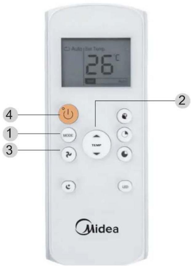
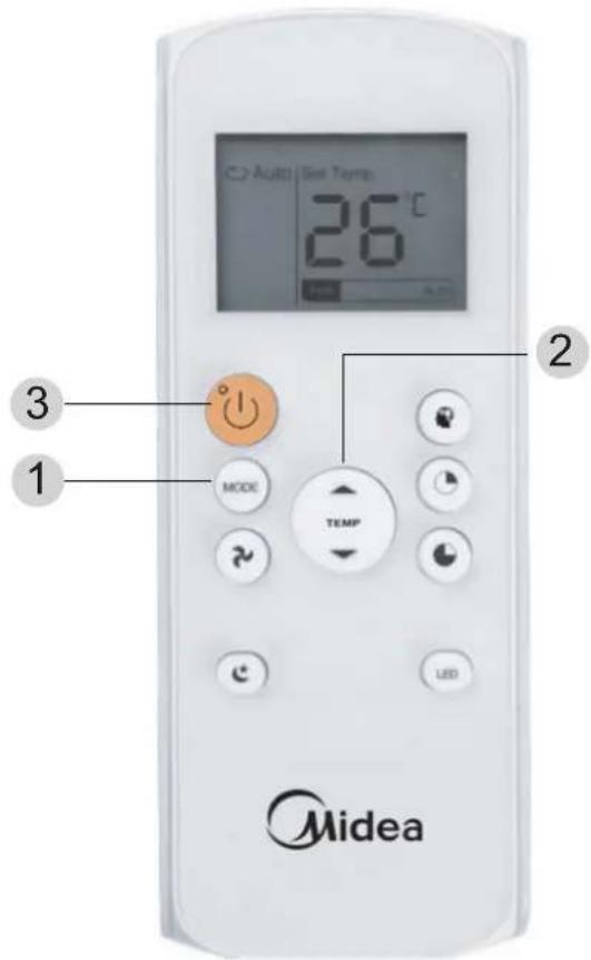
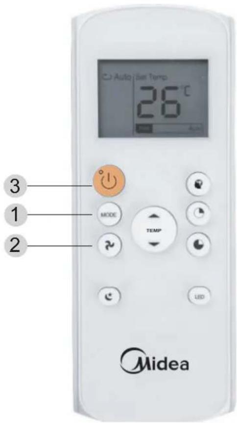
Control Panel Features
NOTE: The following control panels are for explanation purpose only. The control panel of the unit you purchased may be slightly different according to the models. Your machine may not contain some indicators or buttons. The actual shape shall prevail.
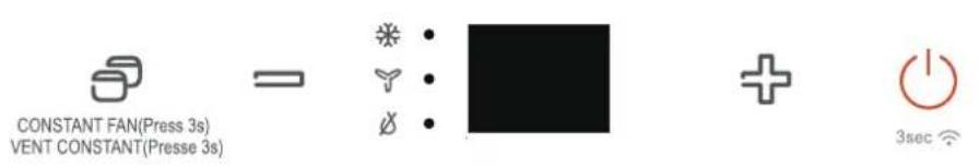

MODE button
Selects the appropriate operating mode. Each time you press the button, a mode is selected in a sequence that goes from COOL, FAN, DRY, HEAT(on some models), and AUTO(on some models).
The mode indicator light illuminates under the different mode setting.
NOTE: On above modes, the unit operates the auto fan speed automatically.

Up (+) and Down (-) buttonsUsed to adjust (increasing/decreasing) temperature settings in 1°C/2°F(or 1°F) increments in a range of 17°C/62°F to 30°C/88°F (or 86°F).
NOTE: The control is capable of displaying temperature in degrees Fahrenheit or degrees Celsius. To convert from one to the other, press and hold the Up and Down buttons at the same time for 3 seconds.
LED display
Shows the set temperature while on cool, heat or auto mode. While on DRY and FAN modes, it shows the room temperature.
Shows Error codes:
EO-EEPROM error.
E1-Room temperature sensor error.
E2-Evaporator temperature sensor error.
E3-Condenser temperature sensor error (on some models).
E4-Display panel communication error.
EC-Refrigerant leakage detection malfunction(on some models).
Shows protection code:
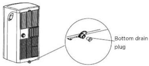
P1-Bottom tray is full--Connect the drain hose and drain the collected water away.
If protection repeats, call for service.
NOTE: When one of the above malfunctions occurs, turn off the unit, and check for any obstructions. Restart the unit, if the malfunction is still present, turn off the unit and unplug the power cord. Contact the manufacturer or its service agents or a similar qualified person for service.

Power button
Power switch on/off.
Operating Instructions
COOL operation
- Press the "MODE" button until the "COOL" indicator light comes on.
- Press the ADJUST buttons "+" or "-" to select your
desired room temperature. The temperature can be set within a range of 17^ C\~ 30^ C/ 62^ F\~ 88^ F(or 86^ F).
- Press the "FAN SPEED" button to choose the fanspeed. (on some models)
DRY operation
- Press the "MODE" button until the "DRY" indicator light comes on.
- The fan speed or the temperature cannot be adjusted. The fan motor operates at LOW speed. (on some models)
NOTE: Keep windows and doors closed for the best dehumidifying effect.
FAN operation
- Press the "MODE" button until the"FAN" indicator light comes on.
- Press the "FAN SPEED" button on the remote controller to choose the fan speed. The temperature can not be adjusted.
- Do not put the duct to window.
AUTO operation(on some models)
- When you set the air conditioner in AUTO mode, it will automatically select cooling, heating(cooling only models without), or fan only operation depending on what temperature you have selected and the room temperature.
- The air conditioner will control room temperature automatically round the temperature point set by you.
- Under AUTO mode, you can not select the fan speed.
NOTE: Under AUTO mode, both the AUTO mode and the actual operation mode indicator lights illuminate for some models.
HEAT operation(cooling only models without)
- Press the "MODE" button until the "HEAT" indicator light comes on.
- Press the ADJUST buttons "+" or "-" to select your desired room temperature. The temperature can be set within a range of 17°C\~30°C/62°F\~88°F (or 86°F).
- Press the "FAN SPEED" button on the remote controller to choose the fan speed.
Wireless operation(on some models)
Used to initiate the wireless connection mode. For the first time to use wireless function, press the POWER button for 3 seconds to initiate the wireless connection mode. The LED DISPLAY shows 'AP' to indicate you can set wireless connection. If connection(router) is successful within 8 minutes, the unit will exit wireless connection mode automatically and the wireless indicator illuminates.
If connection is failure within 8 minutes, the unit exits wireless connection mode automatically. After Wireless connection is successful, for some models you can press MODE and UP (+) buttons at the same time for 3 seconds to turn off Wireless function and the LED DISPLAY shows 'OF' for 3 seconds, press MODE button and UP(+) to turn on Wireless function and the LED DISPLAY shows 'On' for 3 seconds.
NOTE: When you restart the wireless function, it may take a period of time to connect to the networkautomatically.

CONSTANT FAN(Fress 3s) VENT CONSTANT(Presse 3s)
Constant Fan button(On some models) In cooling or Dry mode, press the button for 3 seconds to turn on or off the constant fan function. When the function is turned on, the constant fan light will illuminate, identifying the fan continuous run for cooling. When the function is turned off, the constant fan light will go out, identifying the fan cycle run with compressor stop.
FRESH operation(on some models)
Press MODE and DOWN (-) buttons at the same time for 3 seconds to initiate FRESH feature and the FRESH light illuminantes on some models, the LED DISPLAY shows 'On' for 3 seconds. The ion generator is energized and will help to purify the air inside. Press it for 3 seconds again to stop the FRESH feature and the FRESH light turn dark on some models, the LED DISPLAY shows 'OF' for 3 seconds for some units.
Operating Instructions
SLEEP/ECO operation
This feature can be activated from the remote control ONLY. To activate SLEEP feature, the set temperature will increase(cooling) or decrease(heating) by 1^ C/ 2^ F (or 1^ F) in 30 minutes. The set temperature will then increase(cooling) or decrease(heating) by another 1^ C
NOTE: This feature can be activated from the remote control ONLY. The remote control serves as a remote end of the hose directly over the drain area in your basement floor.
/2°F (or 1°F) after an additional 30 minutes. This new temperature will be maintained for 7 hours before it thermostat allowing for the precise temperature control at its location. To activate the Follow Me/Temp Sensing feature, point the remote control towards the unit and press the Follow Me/Temp Sensing button.
The remote control will send this signal to the air conditioner until press the Follow Me/Temp Sensing button again. If the unit does not receive the Follow Me/Temp Sensing signal during any 7 minutes interval, the unit will exit the Follow Me/Temp Sensing mode.
NOTE: This feature is unavailable under FAN or DRY mode.
AUTO-RESTART
If the unit breaks off unexpectedly due to the power cut, it will restart with the previous function setting automatically when the power resumes.
AIR FLOW DIRECTION ADJUSTMENT Adjust the air flow direction manually:
- The louver can be set to the desired position manually.
- Do not place any heavy objects or other loads on the louver, doing so will cause damage to the unit. Ensure the louver is fully opened under heating operation.
- Keep the louver fully opened during operation.
POWER MANAGEMENT feature(On some models)
Under cooling operation, when the ambient temperature is lower than the setting temperature for a period of time, the unit will be automatically operate power management feature. The compressor and fan motor stop. When the ambient temperature is higher than the setting temperature, the unit will be automatically quit the power management feature.
The compressor and (or) fan motor run.
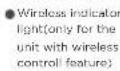
WATER DRAINAGE
- During dehumidifying modes, remove the drain plug from the back of the unit, install the drain
- connector (5/8" universal female mender) with 3/4" hose(locally purchased). For the models without drain connector, just attach the drain hose to the hole. Place the open returns to the
- originally selected temperature. This ends the Sleep mode and the unit will continue to operate as originally programmed.
NOTE: This feature is unavailable under FAN or DRY mode.
FOLLOW ME/TEMP SENSING feature(on some models)
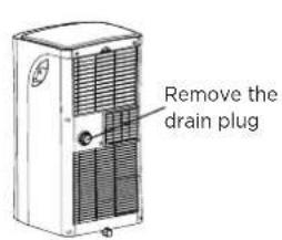
NOTE: Make sure the hose is secure so there are no leaks. Direct the hose toward the drain, making sure that there are no kinks that will stop the warter flowing. Place the end of the hose into the drain and make sure the end of the hose is down to let the water flow smoothly. When the continuous drain hose is not used, ensure that the drain plug and knob are installed firmly to prevent leakage.
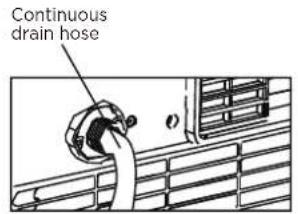
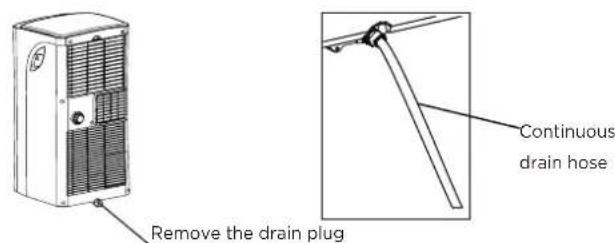
- During heating pump mode, remove the lower drain plug from the back of the unit, install the drain connector(5/8" universal female mender) with 3/4" hose(locally purchased). Carefully move the unit to a drain location, and let the water drain away.
NOTE: Make sure the drain hose is lower than the bottom tray drain outlet.
- When the water level of the bottom tray reaches a predetermined level, the unit beeps 8 times, the digital display area shows "P1". At this time the air conditioning/dehumidification process will immediately stop. However, the fan motor will continue to operate(this is normal). Carefully move the unit to a drain location, remove the bottom drain plug and let the water drain away. Reinstall the bottom drain plug and restart the machine until the "P1" symbol disappears. If the error repeats, call for service.
NOTE: Be sure to reinstall the bottom drain plug firmly to revent leakage before using the unit.
MAINTENANCE
Safety Precautions
• Always unplug the unit before cleaning or servicing.
- DO NOT use flammable liquids or chemicals to clean the unit.
- DO NOT wash the unit under running water. Doing so causes electrical danger.
- DO NOT operate the machine if the power supply was damaged during cleaning. A damaged power cord must be replaced with a new cord from the manufacturer.
Air Filter Cleaning
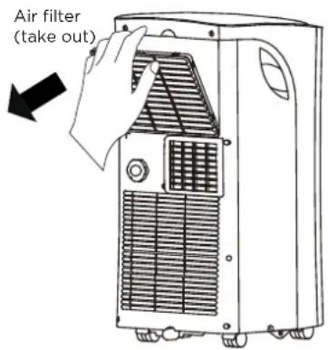
Remove the air filter
CAUTION
DO NOT operate the unit without filter because dirt and lint will clog it and reduce performance.
Maintenance Tips
- Be sure to clean the air filter every 2 weeks for optimal performance.
- The water collection tray should be drained immediately after P1 error occurs, and before storage to prevent mold.
- In households with animals, you will have to periodically wipe down the grill to prevent blocked airflow due to animal hair
Unit Cleaning
Clean the unit using a damp, lint-free cloth and mild detergent. Dry the unit with a dry, lint-free cloth.
Store the unit when not in use
- Drain the unit's water collection tray according to the instructions in the following section.
- Run the appliance on FAN mode for 12 hours in a warm room to dry it and prevent mold.
- Turn off the appliance and unplug it.
- Clean the air filter according to the instructions in the previous section. Reinstall the clean, dry filter before storing.
- Remove the batteries from the remote control.
NOTE: Be sure to store the unit in a cool, dark place. Exposure to direct sunshine or extreme heat can shorten the lifespan of the unit.
NOTE: The cabinet and front may be dusted with an oil-free cloth or washed with a cloth dampened in a solution of warm water and mild liquid dishwashing detergent. Rinse thoroughly and wipe dry. Never use harsh cleansers, wax or polish on the cabinet front. Be sure to wring excess water from the cloth before wiping around the controls. Excess water in or around the controls may cause damage to the unit.
TROUBLESHOOTING TIPS
Problem Possible Causes Solution
| Unit does not turn on when pressing ON/OFF button | P1 Protection Code | The Water Collection Tray is full. Turn off the unit, drain the water from the Water Collection Tray and restart the unit. |
| In COOL mode: room temperature is lower than the set temperature | Reset the temperature | |
| E0 EEPROM error | Contact the manufacturer or its service agents or a similar qualified person for service. | |
| Unit does not cool well | The air filter is blocked with dust or animal hair | Turn off the unit and clean the filter according to instructions |
| Exhaust hose is not connected or is blocked | Turn off the unit, disconnect the hose, check for blockage and reconnect the hose | |
| The unit is low on refrigerant | Call a service technician to inspect the unit and top off refrigerant | |
| Temperature setting is too high | Decrease the set temperature | |
| The windows and doors in the room are open | Make sure all windows and doors are closed | |
| The room area is too large | Double-check the cooling area | |
| There are heat sources inside the room | Remove the heat sources if possible | |
| The unit is noisy and vibrates too much | The ground is not level | Place the unit on a flat, level surface |
| The air filter is blocked with dust or animal hair | Turn off the unit and clean the filter according to instructions | |
| The unit makes a gurgling sound | This sound is caused by the flow of refrigerant inside the unit | This is normal |
Impedance Information
To be in compliance EN 61000-3-11, the product MPPH-08CRN7-QB6 shall be connected only to a supply of the system impedance: | Zsys|=0.451 ohms or less, the product MPPH-09CRN7-QB6G1 shall be connected only to a supply of the system impedance: | Zsys|=0.437 ohms or less, Before connect the product to public power network, please consult your local power supply authority to ensure the power network meet above requirement.
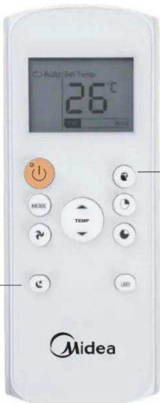
REMOTE CONTROL INSTRUCTIONS
Remote Control Specifications
| Model | RG57H1(B)/BGCUEU1-M |
| Rated voltage | 3.0 V (dry batteries R03/LR03×2) |
| Signal receiving range | 8 m |
| Environment | -5°C~60°C (23°F~140°F) |

CAUTION
INGESTION HAZARD - Contains small batteries, Keep out of reach of small children. If swallowed, seek immediate medical attention.
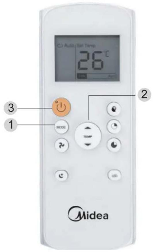
Function Buttons
Before using your new air conditioner, make sure to familiarize yourself with the remote controller. The following is a brief introduction to the remote controller. For instructions on how to operate your air conditioner, refer to the How to Use the Basic Functions" section of this manual.
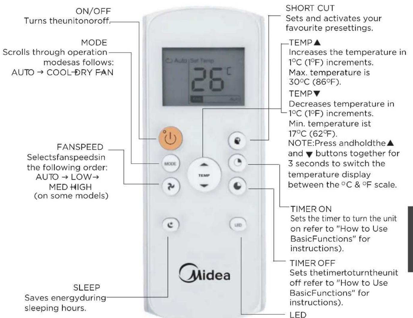
Turns on off indoor unit's LED display.
NOTE: If you are sensitive to light when you go to sleep, you can press the LED button to turn off the LED display on the unit. Press the button again to turn it back on.
Handling the Remote Controller
UNSURE ABOUT A FUNCTION
Refer to the "How to Use Basic Functions" and "How to Use Advanced Functions" sections of this manual for a detailed description of how to use your air conditioner.
SPECIAL NOTE
- Button designs on your unit may differ slightly from the example shown.
- If the unit does not have a particular function, pressing that function button on the remote controller will have no effect.
- If the function description in the OPERATOR'S MANUAL and "Remote Controller Illustration" is significantly different, the description in the OPERATOR'S MANUAL shall prevail.
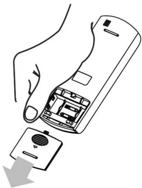
Inserting and Replacing Batteries
Your air conditioning unit comes with two AAA batteries.
Put the batteries in the remote controller before use.
- Slide the back cover from the remote controller downward, to expose the battery compartment.
- Insert the batteries, making sure to match up the (+) and (-) ends of the batteries with the symbols inside the battery compartment.
- Slide the battery cover back into place.
BATTERY NOTES
For optimum product performance:
- Do not mix old and new batteries. Do not mix alkaline, standard(carbon-zinc),or rechargeable(ni-cad,-ni-mh,etc) batteries.
- Do not leave controller if not batteries planning in to the use remote device for more than 2 months.
BATTERY DISPOSAL
Do not dispose of batteries as unsorted municipal waste.
Refer to local laws for proper disposal of batteries.
TIPS FOR USING THE REMOTE CONTROLLER
- The remote controller must be used within 8 meters of the unit.
- The unit will beep when the remote signal is received.
- Curtains, other materials, and direct sunlight can interfere with the infrared signal receiver.
- Remove batteries if the remote will not be used for more than 2 months.
natural_image
Line drawing of a hand holding a remote control device with a button and arrow indicating action (no text or symbols)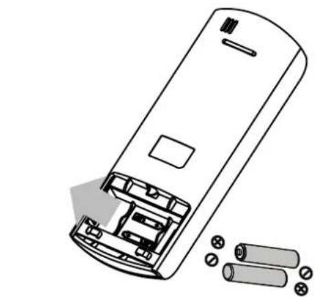
natural_image
Line drawing of a remote control casing with battery pack and battery stack (no text or symbols)
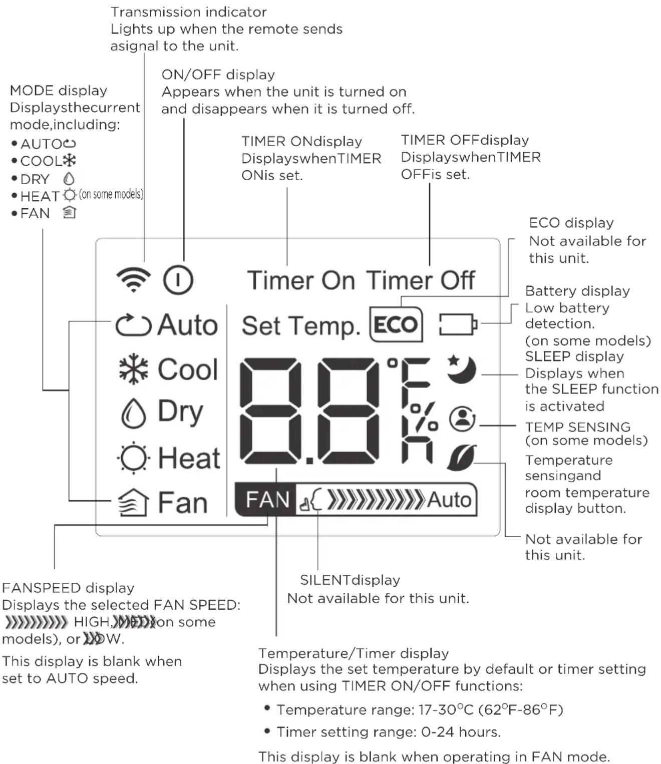
Remote LED Screen Indicators
How to Use the Basic Functions
UNSURE ABOUT A FUNCTION
Refer to the "How to Use Basic Functions" and "How to Use Advanced Functions" sections of this manual for a detailed description of how to use your air conditioner.
COOL Operation
- Press the MODE button to select the COOL mode.
- Set your desired temperature using the Temp ▲ or ▼ Temp button.
- Press the FAN button to select the fan speed: AUTO, LOW, MED(on some models), or HIGH.
- Press the ON/OFF button to start the unit.
SETTING THE TEMPERATURE
The operating temperature range for units is 17-30°C (62°F-86°F). You can increase or decrease the set temperature in 1°C (1°F) increments.
AUTO Operation
In Auto mode, the unit will automatically select the COOL, FAN, HEAT(on some models), or DRY mode based on the set temperature.
- Press the MODE button to select Auto THE mode.
- Set your desired temperature using the Temp ▲ or ▼ Temp button.
- Press the ON/OFF button to start the unit.
NOTE: FAN SPEED cannot be set in Auto mode.
How to Use the Basic Functions
FAN Operation
- Press the MODE button to select the FAN mode.
- Press the FAN button to select the fan speed: AUTO, LOW, MED(on some models), or HIGH.
- Press the ON/OFF button to start the unit.
NOTE: The temperature cannot be set in FAN mode. As a result, your remote controller's LCD screen will not display the temperature.
DRY Operation (dehumidifying)
- Press the MODE button to select the DRY mode.
- Set your desired temperature using the Temp ▲ or ▼ Temp button.
- Press the ON/OFF button to start the unit.
NOTE: FAN SPEED cannot be changed in DRY mode.
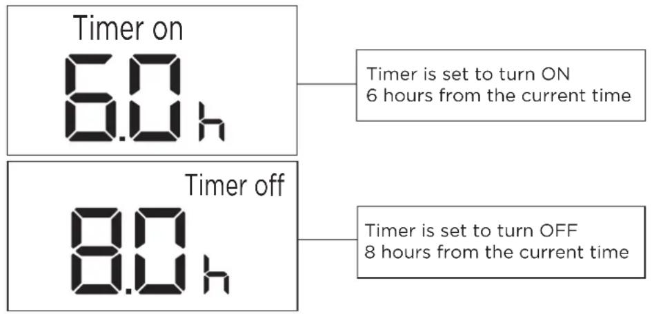
Setting the TIMER Function
Your air conditioning unit has two timer-related functions:
TIMER ON- sets the amount of time after which the unit will automatically turn on.
TIMER OFF- sets the amount of time after which the unit will automatically turn off.
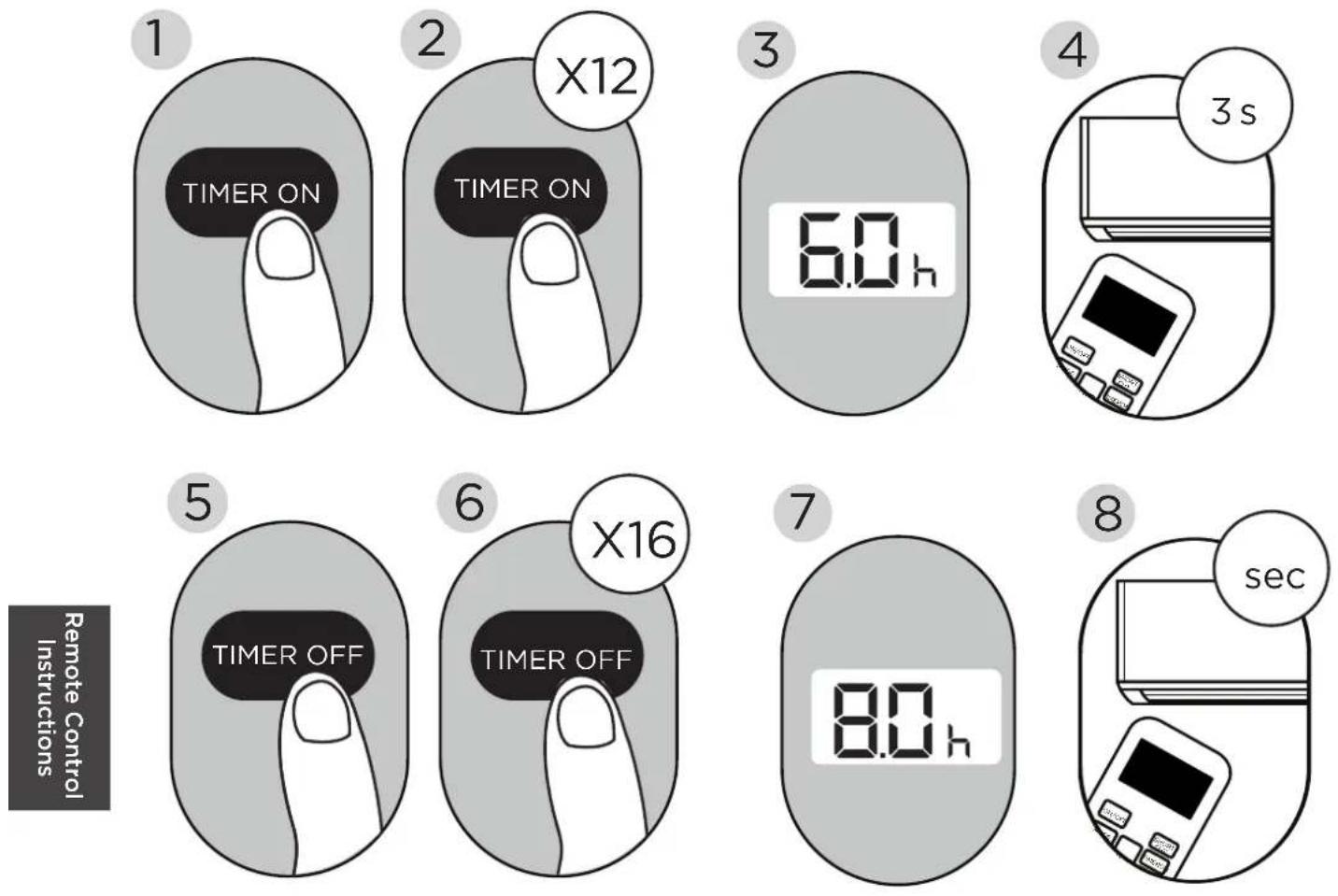
TIMER ON Function
The TIMER ON function allows you to set a period of time after which the unit will automatically turn on, for instance when you come home from work.
- Press the TIMER ON button. By default, the last time period that you set and an "h" (indicating hours) will appear on the display.
Note: This number indicates the amount of time after the current time that you want the unit to turn on.
For example, if you set TIMER ON for 2 hours (2.0 h) will appear on the screen and the unit will turn on after 2 hours.
-
Press the TIMER ON button repeatedly to set the time when you want the unit to turn on.
-
Wait 2 seconds, then the TIMER ON function will be activated. Your remote controller digital display will then go back to the temperature display.
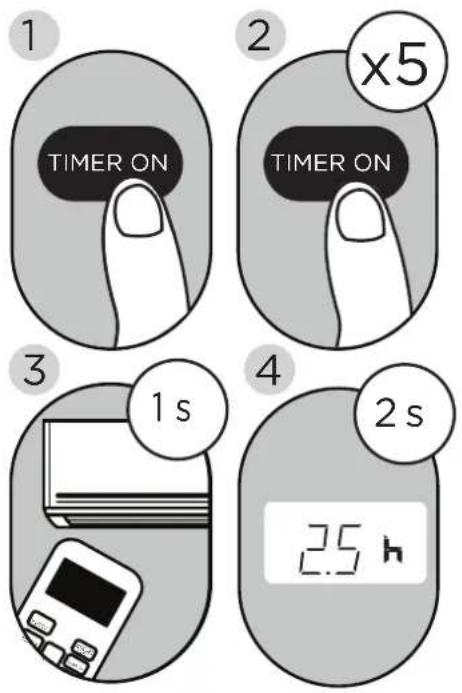
Example: Unit set to turn on after 2.5 hours.
TIMER OFF Function
The TIMER OFF function allows you to set a period of time after which the unit will automatically turn off for instance when you wake up.
- Press the TIMER OFF button. By default, the last time period that you set and an "h" (indicating hours) will appear on the display.
Note: This number indicates the amount of time after the current time that you want the unit to turn off.
For example, if you set TIMER OFF for 2 hours (2.0 h) will appear on the screen and the unit will turn off after 2 hours.
- Press the TIMER OFF button repeatedly to set the time when you want the unit to turn off.
- Wait 2 seconds, then the TIMER OFF function will be activated. Your remote controller digital display will then go back to the temperature display.
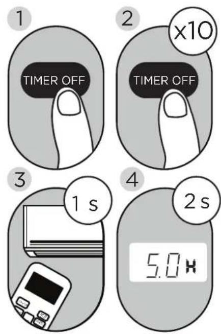
Example: Unit set to turn off after 5 hours.
NOTE: When setting the TIMER ON or TIMER OFF functions up to 10 hours, the time will increase in 30-minute increments with each press. After 10 hours and up to 24 hours, it will increase in 1-hour increments. The timer will revert to zero after 24 hours.
You can turn off either function by setting the timer to 0.0h.

Continue to press TIMER ON or TIMER OFF until the desired time is reached.
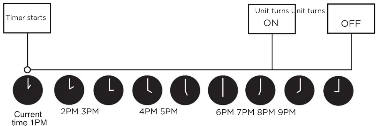
Setting TIMER ON and TIMER OFF at the Same Time
Keep in mind that the time periods you set for both functions refer to hours after the current time. For example, if the current time is 1:00 PM and you want the unit to turn on automatically at 7 PM, operate for 2 hours, and automatically turn off at 9 PM, do the following:
Example: Setting the unit to turn on after 6 hours, operate for 2 hours, then turn off (see the figure below).
Your remote display
flowchart
graph TD
    A["Timer starts"] --> B["Current time 1PM"]
    B --> C["2PM 3PM"]
    C --> D["4PM 5PM"]
    D --> E["6PM 7PM 8PM 9PM"]
    E --> F["OFF"]
    style A fill:#f9f,stroke:#333
    style B fill:#ccf,stroke:#333
    style C fill:#cfc,stroke:#333
    style D fill:#cfc,stroke:#333
    style E fill:#cfc,stroke:#333
    style F fill:#fcc,stroke:#333

How to Use the Advanced Functions
SLEEP Function
The SLEEP function is used to decrease energy use while you sleep (and don't need the same temperature settings to stay comfortable). This function can only be activated via remote control.
NOTE: The SLEEP function is not available in FAN or DRY mode.
SHORTCUT function
• Used to restore the current settings or resume previous settings.
- Push this button when remote controller is on, the system will automatically revert back to the previous settings including operating mode, setting temperature, fan speed level and sleep feature (if activated).
- If pushing more than 2 seconds, the system will automatically restore the current operation settings including operating mode, setting temperature, fan speed level and sleep feature(if activated).
APP INSTRUCTIONS (FOR MAP06R1BWT ONLY)
1 Specification
Unit Model: MAP06R1BWT
Wireless Module Model: US-SK105
Antenna Type: Printed PCB Antenna
Frequency Band: 2400 - 2483.5MHz
Operation Temperature: 0° - 45°C / 32° - 113°F
Operation Humidity: 10% - 85%
Power Input: DC 5V / 500mA
Maximum TX Power: < 20dBm
2 Precautions
- App Compatibility:
- The app is available for both iOS and Android, however older versions may no longer be compatible. Please keep the app updated with the latest version. Midea makes no guarantee of compatibility and is not responsible for issues arising as a consequence thereof.
- The app is subject to updates without prior notice for product function improvement.
- Wireless Security:
- The Smart Kit supports the following security protocols: WPA-PSK / WPA2-PSK / WPA3-SAE
- It may be used with or without encryption although encryption is strongly recommended.
- Connectivity:
- Network issues may occasionally cause timeouts. The unit display and the app may become unsynchronized but this will resolve itself when the network is restored.
- Should the network remain unavailable, it might be necessary to run the configuration process again.
- Change in the wireless network will require reconfiguration of the device.
- Configuration:
- The actual network configuration process may vary slightly from the manual.
- Please check the service website for more information.
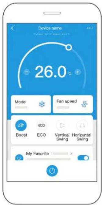
3 Using the SmartHome App

Ensure that your mobile phone is connected to the wireless network. Bluetooth must be turned on. The device must also be powered up.
Step 1: Download the SmartHome app
Scan the QR code below to download the SmartHome app from app store or search for it directly on the Google Play Store or Apple's App Store.


Step 2: Log in
Open the SmartHome app. Log in directly if you have an existing SmartHome account or create a new account.
Alternatively, you can also use a 3rd party login platform.


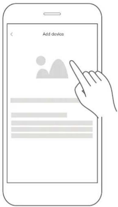
Step 3: Connecting the device
1) When you log in, you may see the message "Smart devices discovered nearby". Tap to add your device.
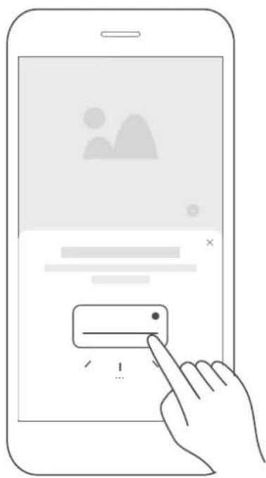
2) If no such message appears, proceed as follows:
Tap on "+" and select your device in the list of nearby available devices.
If your device is not listed, please add your device manually, first selecting the device category e.g. Portable AC.

3) Follow the steps in the app to connect your device to the wireless network. If your device fails to connect, follow the additional instructions in the app.
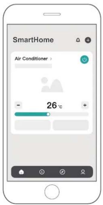
Step 4: Controlling the device
After pairing successfully, a card will be created for the device in the SmartHome app. Shortcuts for basic functions will appear on the card such as changing the temperature or switching the device on or off.
Tapping on the card, will reveal additional features and settings. The actual UI design may look different from examples due to app updates.

4 Compliance
We, hereby declare that this AC is in compliance with the relevant provisions of RE Directive 2014/53/EU. A copy of the full DoC is attached (Europen Union products only).
Wireless module models:
US-SK105:
FCC ID: 2ADQOMDNA21
IC: 12575A-MDNA21
This device complies with Part 15 of the FCC Rules and it contains licence exempt transmitter(s) / receiver(s) that comply with Innovation, Science and Economic Development Canada's licence-exempt RSS(s).
Operation is subject to the following two conditions:
(1) This device may not cause harmful interference;
(2) This device must accept any interference, including interference that may cause undesired operation of the device.
Only operate the device in accordance with the instructions supplied.
Changes or modifications to this unit not expressly approved by the party responsible for compliance could void the user's authority to operate the equipment.
This device complies with FCC radiation exposure limits set forth for an uncontrolled environment. In order to avoid the possibility of exceeding the FCC radio frequency exposure limits, human proximity to the antenna shall not be less than 20cm (8 inches) during normal operation.
In Canada:
CAN ICES-3(B)/NMB-3(B)
-Buttons design is based on typical model and might be slightly different from the actual one you purchased, the actual shape shall prevail.
-All the functions described are accomplished by the unit, if the unit has no this feature, there is no corresponding operation happened when press the relative button on the remote controller.
-When there are wide differences between "Remote controller Illustration" and "USER'S MANUAL" on function description, the description on "USER'S MANUAL" shall prevail.
- The device could comply with the local national regulations. In Canada, it should comply with CAN ICES-3(B)/NMB-3(B). In USA, this device complies with part 15 of the FCC Rules. Operation is subject to the following two conditions: (1) This device may not cause harmful interference, and (2) this device must accept any interference received, including interference that may cause undesired operation.
-This equipment has been tested and found to comply with the limits for a Class B digital device, pursuant to part 15 of the FCC Rules. These limits are designed to provide reasonable protection against harmful interference in a residential installation. This equipment generates, uses and can radiate radio frequency energy and, if not installed and used in accordance with the instructions, may cause harmful interference to radio communications. However, there is no guarantee that interference will not occur in a particular installation. If this equipment does cause harmful interference to radio or television reception, which can be determined by turning the equipment off and on, the user is encouraged to try to correct the interference by one or more of the following measures:
•Reorient or relocate the receiving antenna.
- Increase the separation between the equipment and receiver.
- Connect the equipment into an outlet on a circuit different from that to which the receiver is connected.
- Consult the dealer or an experienced radio/TV technician for help. Changes or modifications not approved by the party responsible for compliance could void suer's authority to operate the equipment.
AIR CONDITIONER LIMITED WARRANTY
Your product is protected by this Limited Warranty:
Warranty service must be obtained from Midea Consumer Services or an authorized Midea servicer.
Warranty
• One year full warranty from original purchase date.
- Limited 2nd through 5th year sealed system warranty*
Midea, through its authorized servicers will:
• Pay all costs for repairing or replacing parts of this appliance which prove to be defective in materials or workmanship.
*For limited 2nd through 5th year sealed system warranty, Midea will replace any part in the sealed refrigeration system (compressor, condenser, evaporator and tubing) which proves to be defective in materials or workmanship.
Consumer will be responsible for:
• Diagnostics, removal, transportation and reinstallation cost required because of service.
• Costs of service calls that are a result of items listed under NORMAL RESPONSIBILITIES OF THE CONSUMER**
Midea replacement parts shall be used and will be warranted only for the period remaining on the original warranty.
NORMAL RESPONSIBILITIES OF THE CONSUMER\*\*
This warranty applies only to products in ordinary household use, and the consumer is responsible for the items listed below:
- Proper use of the appliance in accordance with instructions provided with the product.
- Routine maintenance and cleaning necessary to keep the good working condition.
- Proper installation by an authorized service professional in accordance with instructions provided with the appliance and in accordance with all local plumbing, electrical and / or gas codes.
- Proper connection to a grounded power supply of sufficient voltage, replacement of blown fuses, repair of loosen connections or defects in house wiring.
- Expenses for making the appliance accessible for servicing.
- Damages to finish after installation.
EXCLUSIONS
This warranty does not cover the following:
1) Failure caused by damage to the unit while in your possession (other than damage caused by defect or malfunction), by its improper installation, or by unreasonable use of the unit, including without limitation, failure to provide reasonable and necessary maintenance or to follow the written Installation and Operating Instructions.
2) Damages caused by services performed by persons other than authorized Midea servicers; use of parts other than Midea replacement parts; obtained from persons other than such Midea customer service; or external causes such as abuse, misuse, inadequate power supply or acts of God.
3) If the unit is put to commercial, business, rental, or other use or application other than for consumer use, we make no warranties, express or implied, including but not limited to, any implied warranty of merchantability or fitness for particular use or purpose.
4) Products without original serial numbers or products that have serial numbers which have been altered or cannot be readily determined.
Note: Some states do not allow the exclusion or limitation of incidental or consequential damages. So this limitation or exclusion may not apply to you.
IF YOU NEED SERVICE
Keep your bill of sale, delivery slip, or some other appropriate payment record.
The date on the bill establishes the warranty period, should service be required. If service is performed, it is your best interest to obtain and keep all receipts.
This written warranty gives you specific legal rights. You may also have other rights that vary from state to state.
Service under this warranty must be obtained by following these steps, in order:
- Contact Midea Consumer Services or an authorized Midea servicer at 1-888-365-2230
- If there is a question as to where to obtain service, contact our consumer relations Department.

make yourself at home

www.midea.com
© Midea 2023 all rights reserved
16120300A31907
20231225
natural_image
Technical line drawing of a rectangular electronic device with internal grid structure (no text or symbols)
natural_image
Line drawing of a portable air conditioner unit with ventilation slots and mounting feet (no text or symbols)
CLIMATISEUR PORTATIF


SmartHome
Our customer service staff is available to help you. For any problem with your purchase, or to receive further information about this product, please call our toll-free number.
SAVE THIS MANUAL
Keep this manual and the original sales invoice in a safe, dry place for future reference.
NSTRUCTIONS DE L'APPLICATION (POUR MAP06R1BWT UNIQUEMENT) 37
GARANTIE LIMITÉE DES CLIMATISEURS 43
PRÉCAUTIONS DE SÉCURITÉ
natural_image
Mechanical assembly diagram showing a pipe connection before and after modification (no text or symbols)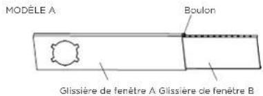
natural_image
Line drawing of a device emitting a hose, mounted on a base (no text or symbols)Ou
natural_image
Line drawing of a printer with a coiled cable inserted into a screen (no text or symbols)natural_image
Three hand-drawn diagrams of pipe fittings, showing different types of pipe connection (no text or symbols)MODE D'EMPLOI
- Press the "FAN SPEED" button on the remote controller to choose the fan speed.
Operating Instructions
natural_image
Line drawing of a hand opening a portable air conditioner unit with ventilation grilles (no text or symbols)natural_image
Line drawing of a hand holding a remote control device with a button and arrow indicating action (no text or symbols)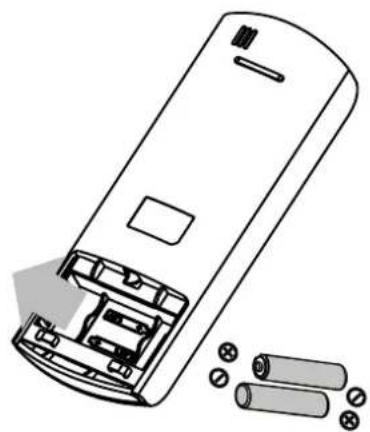
natural_image
Diagram of a remote control casing with battery pack and cylindrical components (no text or symbols)
Fonction SHORTCUT (raccourci)
NSTRUCTIONS DE L'APPLICATION (POUR MAP06R1BWT UNIQUEMENT)
1 Spécifications
Modèle : MAP06R1BWT

© Midea 2023 all rights reserved
16120300A31907
20231225