
PCI30BCVW6BB - Oven CANDY - Free user manual and instructions
Find the device manual for free PCI30BCVW6BB CANDY in PDF.

| Product Type | Built-in Oven |
| Brand | Candy |
| Model | PCI30BCVW6BB |
| Dimensions (W x D x H) | 595 x 595 x 550 mm (estimated) |
| Weight | Approximately 35 kg |
| Power Supply | 220-240 V ~ 50/60 Hz |
| Maximum Power | Approximately 2500 W |
| Capacity | Approximately 65 liters |
| Cooking Functions | Natural convection, bottom heat, grill |
| Interior Lighting | Replaceable bulb (class G) |
| Installation Type | Built-in under counter or in column |
| Door Material | Glass |
| Included Accessories | Metal grid, drip tray, collection tray |
| Child Safety | Lock function available (mentioned in manual) |
| Recommended Cleaning | Soapy water, non-abrasive sponge; avoid abrasive products |
| Bulb Maintenance | Unplug, unscrew cover, replace with identical bulb |
| Energy Class | Not specified (compliant with EN 60350-1) |
| Warranty | Contact after-sales service |
Frequently Asked Questions - PCI30BCVW6BB CANDY
User questions about PCI30BCVW6BB CANDY
0 question about this device. Answer the ones you know or ask your own.
Ask a new question about this device
Download the instructions for your Oven in PDF format for free! Find your manual PCI30BCVW6BB - CANDY and take your electronic device back in hand. On this page are published all the documents necessary for the use of your device. PCI30BCVW6BB by CANDY.
USER MANUAL PCI30BCVW6BB CANDY
natural_image
Line drawings of a gas stove with four identical fan-shaped burners and control knobs (no text or symbols)SAFETY INSTURUCTIONS
We recommend you keep the instructions for installation and use for later reference, and before installing the hob, note its serial number in case you need to get help from the after sales service. WARNING: the appliance and its accessible parts become hot during use. Care should be taken to avoid touching heating elements. Children under 8 years of age must be kept away from the appliance unless they are continuously supervised.
WARNING: use only hob guards designed by the Manufacturer of the cooking appliance or indicated by the Manufacturer of the appliance in the instructions for use as suitable or hob guards incorporated in the appliance. The use of inappropriate guards can cause accidents.
WARNING: unattended cooking on a hob with fat or oil can be dangerous and may result in fire. NEVER try to extinguish a fire with water, but switch off the appliance and then cover flame e.g. with a lid or a fire blanket.
WARNING: danger of fire: do not store items on the cooking surfaces.
WARNING: if the surface is cracked, do not touch the glass and switch off the appliance to avoid the possibility of electric shock.
This appliance can be used by children aged from 8 years and above and people with reduced physical, sensory or mental capabilities or lack of experience and knowledge if they have been given supervision or instruction concerning use of the appliance in a safe way and understand the hazards involved. Children should be supervised to ensure that they do not play with the appliance. Cleaning and user maintenance shall not be made by children without supervision.
CAUTION: the cooking process must be supervised. A short term cooking process has to be supervised continuously.
It is strongly recommended to keep children away from the cooking zones while they are in operation or when they are switched off, so long as the residual heat indicator is on, in order to prevent the risks of serious burns.
This appliance is not intended to be operated by means of an external timer or separate remote control system.
If present do not to stare into halogen lamp hob elements.
Connect a plug to the supply cable that is able to bear the voltage, current and load indicated on the tag and having the earth contact. The socket must be suitable for the load indicated on the tag and must be having the earth contact connected and in operation. The earth conductor is yellow-green in color. This operation should be carried out by a suitably qualified professional. In case of incompatibility between the socket and the appliance plug, ask a qualified electrician to substitute the socket with another suitable type.
The plug and the socket must be conformed to the current norms of the installation country. Connection to the power source can also be made by placing an omnipolar breaker between the appliance and the power source that can bear the maximum connected load and that is in line with current legislation.
The yellow-green earth cable should not be interrupted by the breaker. The socket or omnipolar breaker used for the connection should be easily accessible when the appliance is installed.
The disconnection may be achieved by having the plug accessible or by incorporating a switch in the fixed wiring in accordance with the wiring rules.
If the supply cord is damaged, it must be replaced by Manufacturer, its service agent or similarly qualified people in order to avoid a hazard. The earth conductor (yellow-green) must be longer than 10 mm on the terminal block side. The internal conductors section should be appropriate to the power absorbed by the hob (indicated on the tag). The type of power cable must be H05 GG-F.
Do not put metallic objects such as knives, forks, spoons or lids on the hob. They could heat up. Aluminum foil and plastic pans must not be placed on heating zones.
After every use, some cleaning of the hob is necessary to prevent the build-up of dirt and grease. If left, this is recooked when the hob is used and burns giving off smoke and unpleasant smells, not to mention the risks of fire propagation.
Never use a steam or high pressure spray to clean the appliance.
Do not touch the heat zones during operation or for a while after use.
Never cook food directly on the glass ceramic hob.
Always use the appropriate cookware. Always place the pan in the center of the unit that you are cooking on.
Do not place anything on control panel.
Do not use the hob as a working surface.
Do not use the surface as a cutting board.
Do not store heavy items above the hob. If they drop onto the hob, they may cause damage.
Do not use the hob for storage of any items.
Do not slide cookware across the hob.
No additional operation/setting is required in order to operate the appliance at the rated frequencies.
In case of hotplate glass breakage:
Shut immediately off all burners and electrical heating element and isolate the appliance from the power supply.
Do not touch the appliance surface.
Do not use the appliance.
1. INSTRUCTIONS FOR THE INSTALLER
INSTALLING A DOMESTIC APPLIANCE CAN BE A COMPLICATED OPERATION WHICH IF NOT CARRIED OUT CORRECTLY, CAN SERIOUSLY AFFECT CONSUMER SAFETY. IT IS FOR THIS REASON THAT THE TASK SHOULD BE UNDERTAKEN BY A PROFESSIONALLY QUALIFIED PERSON WHO WILL CARRY IT OUT IN ACCORDANCE WITH THE TECHNICAL REGULATIONS IN FORCE. IN THE EVENT THAT THIS ADVICE IS IGNORED AND THE INSTALLATION IS CARRIED OUT BY AN UNQUALIFIED PERSON, THE MANUFACTURER DECLINES ALL RESPONSIBILITY FOR ANY TECHNICAL FAILURE OF THE PRODUCT WHETHER OR NOT IT RESULTS IN DAMAGE TO GOODS OR INJURY TO INDIVIDUALS.
1.1 BUILDING IN
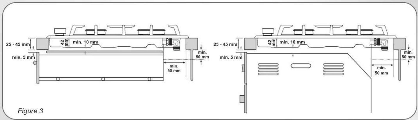
The hob may be installed in any worktop which is heat resistant to a temperature of 100^ C, and has a thickness of 25-45 mm. The dimensions of the insert to be cut out of the worktop are in shown in Figure 2.
When there is an accessible space between the built-in hob and the cavity below, a dividing wall made of insulating material should be inserted (wood or a similar material) (Figure 3).
If the Hob is fitted next to a cabinet on either side, the distance between the Hob and the cabinet must be at least ; while 17 cm (see Figure 2) the distance between the hob and the rear wall must be at least .70 mm The distance between the hob and any other unit or appliance above it (e.g. An extractor hood) must be no less than 70 cm . (Figure 4)
Metal objects in the drawer may reach high temperatures due to air recirculation. It is therefore recommended to use an intermediate wood panel.
Important - The diagram in figure 1 shows how the sealant should be applied.
The Hob unit is fitted by attaching the Fixing Clamps supplied, using the holes at the base of the unit.
If a hob of 60 cm is fitted above an oven which is not equipped with fan cooling system it is recommended that openings are created within the built in furniture to ensure correct air circulation.
The size of these openings must be at least 300 cm2 and placed as shown in Figure 5.
1.2. SUITABLE LOCATION
This appliance must be installed in accordance with the regulations in force and only used in a well ventilated space. Read the instructions before installing or using this appliance.
A gas-powered cooking appliance produces heat and humidity in the area in which it is installed. For this reason you should ensure good ventilation either by keeping all natural air passages open or by installing an extractor hood with an exhaust flue. Intensive and prolonged use of the appliance may require extra ventilation, such as the opening of a window or an increase in speed of the electric fan, if you have one.
If a hood can not be installed, an electric fan should be fitted to an outside wall or window to ensure that there is adequate ventilation. The electric fan should be able to carry out a complete change of air in the kitchen 3-5 times every hour. The installer should follow the relevant national standards.
2. ELECTRICAL CONNECTION (FOR U.K. ONLY)
Warning - this appliance must be earthed
This appliance is designed for domestic use only. Connection to the main supply must be made by a competent electrician, ensuring that all current regulations concerning such installations are observed.
The appliance must only be connected to a suitably rated spur point, a 3 pin 13 amp plug/socket is not suitable. A double pole switch must be provided and the circuit must have appropriate fuse protection. Further details of the power requirement of the individual product will be found in the users' instruction and on the appliance rating plate. In the case of built-in product you are advised, should you wish to use a longer cable than the one supplied, that a suitably rated heat resistant type must be used.
The wiring must be connected to the mains supply as follows:
CONNECT TO SPUR TERMINAL
Green & Yellow Wire
Earth Connection
Blue Wire
Neutral Connection
Brown Wire
Live Connection
Note: We do not advocate the use of earth leakage devices with electric cooking appliances installed to spur points because of the «nuisance tripping» which may occur. You are again reminded that the appliance must be correctly earthed, the manufacturer declines any responsibility for any event occurring as a result of incorrect electrical installation.
2.1. ELECTRICAL CONNECTION
Check the data on the rating plate, located on the outside of the unit, to ensure that the supply and input voltage are suitable.
Before connection, check the earthing system.
By Law, this appliance must be earthed. If this regulation is not complied with, the Manufacturer will not be responsible for any damage caused to persons or property. If a plug is not already attached, fit a plug appropriate to the load indicated on the rating plate. The earth wire is coloured yellow/green. The plug should always be accessible.
Where the Hob is connected direct to the electricity supply, a circuit breaker must be fitted.
If the power supply cord is damaged this is to be replaced by a qualified engineer so as to prevent any potential risk.
The earth wire (green and yellow coloured) must be at least 10 mm longer than the live and neutral wires.
The section of the cable used must be of the correct size in relation to the absorbed power of the hob.
Please check rating plate for the power details and ensure that the power supply cord is of the type 3x0.75 mm² H05 GG-F.
| Mains Supply | LIVE | L | Brown Wire |
| EARTH | Green/Yellow Wire | ||
| NEUTRAL | N | Blue Wire |
If an appliance is not fitted with a supply cord and a plug, or with other means for disconnection from the supply mains having a contact separation in all poles that provide full disconnection under overvoltage category III conditions, the instructions shall state that means for disconnection must be incorporated in the fixed wiring in accordance with the wiring rules.
2.2. GAS CONNECTION
These instructions are for qualified personnel, installation of equipment must be in line with the relevant national standard. (For U.K. only: by law the gas installation\commissioning must be carried out by a "Gas Safe" installer)
All work must be carried out with the electricity supply disconnected.
The rating plate on the hob shows the type of gas with which it is designed to be used. Connection to the mains gas supply or gas cylinder should be carried out after having checked that it is regulated for the type of gas with which it will be supplied. If it is not correctly regulated see the instructions in the following paragraphs to change gas setting.
For liquid gas (cylinder gas) use pressure regulators which comply with the relevant national standards.
Use only pipes, washers and sealing washers which comply with the relevant national standards.
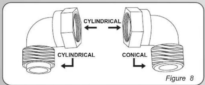
For some models a conic link is furnished to outfit for the installation in the countries where this type of link is obligatory; in picture 8 it is pointed out how to recognize the different types of links (CY = cylindrical, CO = conic). In every case the cylindrical part of the link has to be connected to the hob.
When connecting the hob to the gas supply via use offlexible hoses please ensure that the maximum distance covered by the hose does not exceed 2 metres.
The flexible tube shall be fitted in such a way that it cannot come into contact with a moveable part of the housing unit (e.g. a drawer) and does not pass through any space where it may become crushed/ kinked or damaged in any way.
To prevent any potential damage to the hob please carry out the installation following this sequence (picture 6):
1) As illustrated, assemble parts in sequence:
A: 1/2 Male Adaptor Cylindrical
B: 1/2 Seal
C: 1/2 Female Gas Adaptor Conical-Cylindrical or Cylindrical-Cylindrical
2) Tighten the joints with the spanner, remembering to twist the pipes into position.
3) Attach fitting C to mains gas supply using rigid copper pipe or flexible steel pipe.
IMPORTANT: carry out a final check for leaks on the pipe connections using a soapy solution. NEVER USE A FLAME. Also, make sure that the flexible pipe cannot come into contact with a moving part of the cabinet (eg.adrawer) and that it is not situated where it could be damaged.
Warning: If gas can be smelt in the vicinity of this appliance turn off the gas supply to the appliance and call the engineer directly. Do not search for a leak with a naked flame.
2.3. ADAPTING THE HOB TO DIFFERENT TYPES OF GAS
To adapt the Hob for use with different types of gas, carry out the following instructions:
- Remove the grids and burners
- Insert on hexagonal spanner (7 mm) into the burner support (Figure7)
- Unscrew the injector and replace it with one suitable for the gas to be used (see gas type table)
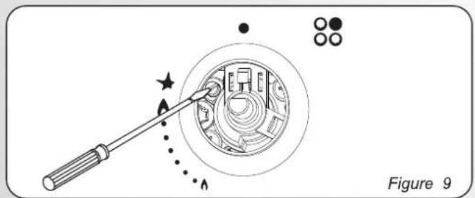
2.4. REGULATING THE MINIMUM FLAME
After lighting the burners, turn the control knob to the minimum setting and then remove the knob (this can easily be removed by applying gentle pressure).
Using a small «Terminal» type screwdriver the regulating screw can be adjusted as in Figure 9. Turning the screw clockwise reduces the gas flow, whilst turning it anticlockwise increases the flow – Use this adjustment to obtain a flame of approximately 3 to 4 mm in length and then replace the control knob.
When the gas supply available is LPG - the screw to set the idle flame must be turned (clockwise) to the end stop.
When you have carried out the new gas regulation, replace the old gas rating plate on your appliance with one (supplied with hob) suitable for the type of gas for which it has been regulated.
3. USE OF HOB - USER INSTRUCTIONS
This appliance must only be used for the purpose for which it is intended, domestic cooking, and any other use will be considered improper and could therefore be dangerous. The Manufacturer will not be responsible for any damage or loss resulting from improper use.
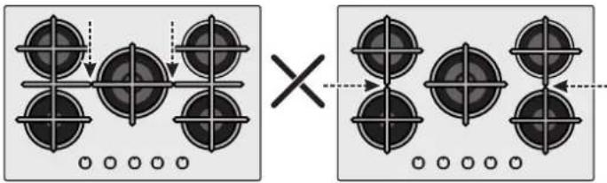
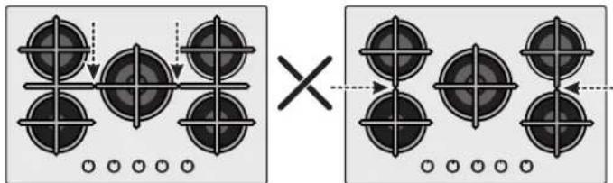
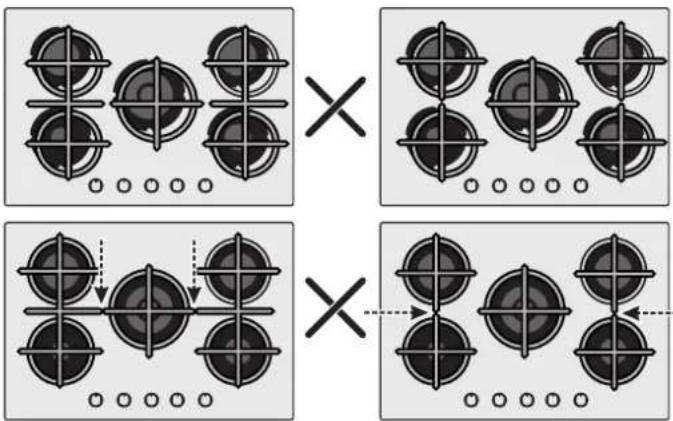
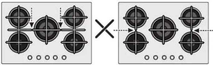
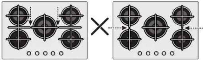
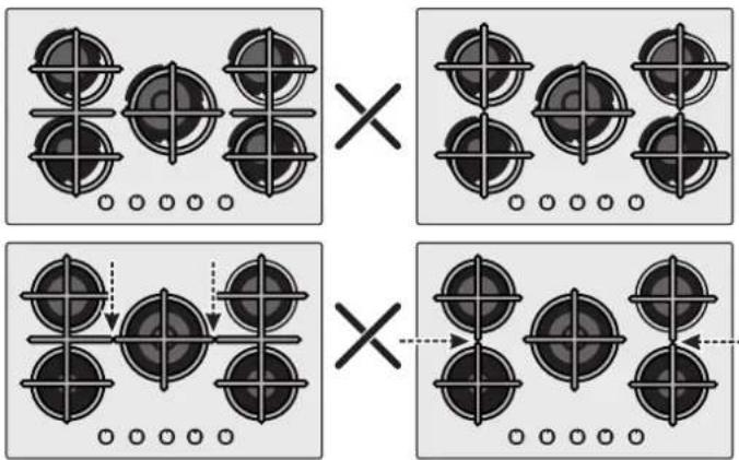
Before using burner, be sure, grid perimeters center the burner as below figure.
If you are using Cast Iron Grids; underneath the grid, position of it is stated. Be sure for the exact grid is used in correct position.

Prior to switching on the gas hob ensure that the burners and burner caps are correctly placed within their position.
This hob is fitted with electronic ignition to ignite the burner.
To ignite the burners carry out the following:
° push in and turn the knob anticlockwise to the larger flame symbol and keep pushed 5 s after ignition.
The ignition system will continue to generate sparks as long as the control knob is being pressed
Warning: If there is no electricity on appliance to ignite the burner a match or a lighter should be used carrying out the following:
°place a lighted match or lighter close to the burner
°Push in and turn the knob anticlockwise to the larger flame symbol 6 and keep pushed 5 s after ignition.
Warning: In any case If after 5 s the burner has not lit, stop operating the device and wait at least 1 min before attempting a further ignition of the burner.
GENERAL ADVISE
For best results, use cooking vessels with a flat surface. The size of the surface should match the gas burner side as follows. Table A.
| Burner Type | ∅ pan/pot (cm) | Power (kW) | G20/20 mbar (methane) | G30/28-30 mbar (LPG) |
| AUX Auxiliary | 10 - 18 | 1,00 | 95 l/h | 73 g/h |
| SR Semi Rapid | 12 - 22 | 1,75 | 167 l/h | 127 g/h |
| R Rapid | 16 - 26 | 2,70 | 257 l/h | 196 g/h |
Table A
The gas burner should be regulated so that the flame does not overlap the base of the pan. Vessels with a concave or convex base should not be used.
WARNING: If a flame is accidentally extinguished, turn the knob to the off position and do not attempt to re-ignite if for at least 1 minute.
If over the years the gas taps become stiff to turn it is necessary to lubricate them.
Such operation must be carried out only by qualified Service Engineers.
4. MAINTENANCE AND CLEANING
Before cleaning the hob, ensure the appliance has cooled down. Remove the plug from the socket or (if connected directly) switch off the electricity supply.
Cleaning and user maintenance shall not be made by children without supervision
Never use abrasives, corrosive detergents, bleaching agents or acids. Avoid any acid or alkaline substances (lemon, juice, vinegar etc.) on the enamelled, varnished or stainless steel sections.
When cleaning the enamelled, varnished or chrome sections, use warm soapy water or a non caustic detergent. For stainless steel use an appropriate cleaning solution.
The burners can be cleaned with soapy water. To restore their original shine, use a household stainless steel cleaner. After cleaning, dry the burners and replace.
It is important the Burners are replaced correctly.
Chromed grids and burners
Chromed grids and burners have a tendency to discolour with use. This does not jeopardize the functionality of the hob.
Our After Sales Service Centre can provide spare parts if required.
5. AFTERCARE
Before calling out a Service Engineer please check the following:
- that the plug is correctly inserted and fused;
• that the gas supply is not faulty.
If the fault cannot be detected:
Switch off the appliance and call the After Service Centre. DO NOT TAMPER WITH THE APPLIANCE.
6. PROTECTION OF THE ENVIRONMENT
This appliance is labelled in accordance with European Directive 2012/19/EU regarding electric and electronic appliances (WEEE). The WEEE contain both polluting substances (that can have a negative effect on the environment) and base elements (that can be reused). It is important that the WEEE undergo specific treatments to correctly remove and dispose of the pollutants and recover all
the materials. Individuals can play an important role in ensuring that the WEEE do not become an environmental problem; it is essential to follow a few basic rules:
- The WEEE should not be treated as domestic waste;
- The WEEE should be taken to dedicated collection areas managed by the town council or a registered company.
In many countries, domestic collections may be available for large WEEEs. When you buy a new appliance, the old one can be returned to the vendor who must accept it free of charge as a one-off, as long as the appliance is of an equivalent type and has the same functions as the purchased appliance.
SAVING AND RESPECTING THE ENVIRONMENT
Where possible use lid to cover the pan. Regulate the flame to not overlap the diameter of the pan.
7. DECLARATION OF COMPLIANCE
The appliance complies with European Directive 2009/142/EC (GAD) and starting from 21/04/2018 with Gas Appliances Regulation 2016/426 (GAR).
By placing the CE mark on the product, we are confirming compliance to all relevant European safety, health and environmental requirements which are applicable in legislation for this product.
Table 1
| Burner Plate | 4 Gas - L1 |
| Burner | AUX/2SR/R |
| Type | PVUH60MF |
| FFD | YES |
| AUX 1kW | 1 |
| SR 1,75 kW | 2 |
| R 2,7 kW | 1 |
| DC 4 kW MONO | - |
| Nominal Heat Input | 7.2 kW |
| G20/20 mbar | 686 l/h |
| G30/28-30 mbar | 524 g/h |
| Installation Class | 3 |
| Voltage V/Frequency Hz | 220-240V 50/60Hz |
| Electrical Input Power | 1 |
| Electric Ignition | YES |
| Product Dimension | 595x505x42 |
This appliance has been designed for non-professional, i.e. domestic, use.
CONSIGNES DE SÉCURITÉ
7. DÉCLARATION DE CONFORMITÉ
3.1. POUŽITÍ PLYNOVÉHO HOŘÁKU
3.1. UŻYWANIE PALNIKÓW GAZOWYCH
Tel: 039.2086.1 • Fax: 039.2086.403
www.candy-group.com
CANDY
GARANTI BELGESI
ANKASTRE OCAK
NAVODILA ZA VARNO UPORABO
3.1. UPORABA GORILNIKOV
3.1. COMO UTILIZAR O QUEIMADOR DE GÁS
3.1. A GÁZÉGŐ HASZNÁLATA
3.1 UTILIZAREA ARZĂTOARELOR
3.1. POUŽITIE PLYNOVÉHO HORÁKA
3.1. UPOTREBA PLINSKOG PLAMENIKA
3.1. GAASIPÕLETI KASUTAMINE
KESKKONNA SÄÄSTMINE JA AUSTAMINE
3.1. DUJU DEGIKLIO NAUDOJIMAS
natural_image
Diagram of a rectangular electronic device with internal compartments and a circular connector, labeled Figure 1 (no text or symbols on the device itself)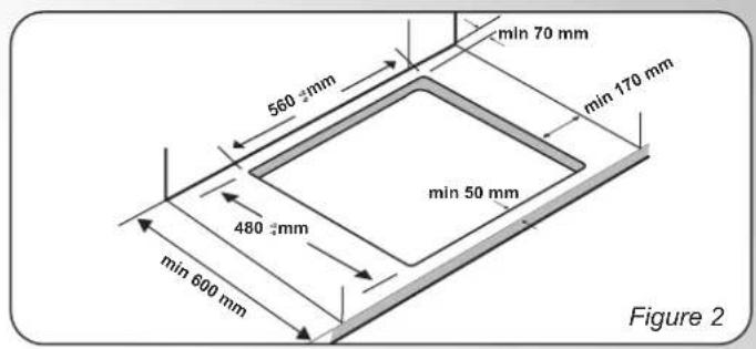
natural_image
Diagram of a rope knot with directional arrows indicating motion (no text or symbols)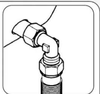
natural_image
Technical line drawing of a mechanical joint or connector (no text or symbols)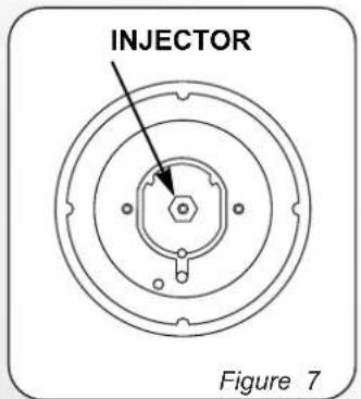
natural_image
Diagram showing a tool interacting with a circular mechanical component, labeled Figure 9 (no text or symbols on the diagram itself)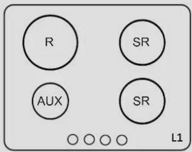
GAS TYPEHOBS
| Gas Type | G20 | G20 | G25.1 | G25.3 | G30/G31 | G30/G31 | G30/G31 | ||
| Gas Pressure | 20 mbar | 25 mbar | 25 mbar | 25 mbar | 28-30 mbar | 37 mbar | 50 mbar | ||
| Burners | Max (kW) | Min (kW) | Injector NG | Injector NG | Injector NG | Injector NG | Injector LPG | Injector LPG | Injector LPG |
| Max - Min | Max - Min | Max - Min | Max - Min | Max - Min | Max - Min | Max - Min | |||
| AUX | 1 | 0,3 | 72X(1kW-0.3kW) | 70X(1kW-0.3kW) | 74F1(1kW-0.3kW) | 72F1(1kW-0.3kW) | 50(73g/h-22g/h) | 46(73g/h-25g/h) | 46H2(73g/h-29g/h) |
| SR | 1,75 | 0,5 | 97Z(1.75kW-0.5kW) | 91Z(1.75kW-0.5kW) | 98Y(1.75kW-0.5kW) | 102F3(1.75kW-0.5kW) | 65(127g/h-36g/h) | 61(127g/h-40g/h) | 58M(127g/h-44g/h) |
| R | 2,7 | 0,8 | 109Y(2.7kW-0.8kW) | 110F3(2.7kW-0.8kW) | 120F2(2.7kW-0.8kW) | 115F2(2.7kW-0.8kW) | 83(196g/h-58g/h) | 78(196g/h-62g/h) | 73S(196g/h-69g/h) |
| Gas Categories | II2E+3+ | II2H3+ | II2H3B/P |
| G20/G25 20/25mbar 2E+ | G20 20mbar 2H | G20 20mbar 2H | |
| G30/G31 28-30/37mbar 3+ | G30/G31 28-30/37mbar 3+ | G30/G31 30/30mbar 3B/P | |
| Countries | BE,FR | CY,CZ,GB,GR,IE,IT,PT,SI, ES,TR,CH | BG, HR,DK,EE,FI,LV,LT,NO,RO,SK,SE,CZ,SI,TR |
| Gas Categories | II2H3B/P | II2HS3B/P II2EK3B/P | II2E3B/P | II2E3B/P | |
| G20 20mbar 2H | G20 20mbar 2E | G20 20mbar 2H | G20 20mbar 2E | G20 20mbar 2E | |
| G30/G31 50/50mbar 3B/P | G25.3 25mbar 2K | G25.1 25mbar 2S | G30/G31 37/37mbar 3B/P | G30/G31 50/50mbar 3B/P | |
| G30/G31 30/30mbar 3B/P | G30/G31 30/30mbar 3B/P | ||||
| Countries | AT,CH | NL | HU | PL | DE |
Efficiency Declaration 2016/426
| PVUH60MF - STANDARD (L1) | |||
| SINGLE BURNER EFFICENCY | |||
| AUX | SR | SR | |
| - | 60% | 60% | 54.3% |
| MEDIUM %58.1 | |||
GB - IE
The manufacturer will not be responsible for any inaccuracy resulting from printing or transcript errors contained in this brochure. We reserve the right to carry out modifications to products as required, including the interests of consumption, without prejudice to the characteristics relating to safety or function.
FR
natural_image
Simple calendar icon with two dots on top and two diagonal lines inside a blank frame (no text or symbols)| Instrukcje użytkownikaPIEKARNIKI | PL | 2 |
| Pokyny pro uživateleTROUBY | CZ | 13 |
| Navodila za uporabnikaPEČICE | SL | 24 |
| Návod na použitieRÚRA NA PEČENIE | SK | 35 |
| Инструкции за потребителяФУРНИ | BG | 46 |
| Upute za korisnikeРЕĆNICE | HR | 57 |
| Однгієх хрніснзФОУРНЕЗ | GR | 68 |
| Uputstvo za korisnikaRERNE | SR | 80 |
| Instrucțiuni de utilizareCUPTOARE | 91 O |
natural_image
Line drawing of a rectangular plastic container with mounting holes and a central slot (no text or symbols)natural_image
Line drawing of a multi-tiered ladder structure (no text or symbols)natural_image
Line drawing of a rectangular metal tray with vertical slats and a handle (no text or symbols)natural_image
Top-down diagram of a square appliance with internal components and directional arrows, no text or symbols present.WYMIANA ŻARÓWKI
natural_image
Symbol of a trash bin crossed with two crossed lines, no text or labels presentPŘÍSLUŠENSTVÍ
Odkapávací plech

natural_image
Line drawing of a rectangular container with mounting flanges (no text or symbols)natural_image
Line drawing of a multi-tiered ladder structure with curved supports (no text or symbols)natural_image
Line drawing of a rectangular metal tray with vertical slats and a handle (no text or symbols)natural_image
Diagram of a square appliance with internal components and numbered arrows indicating flow or placement (no text or symbols)VÝMĚNA ŽÁROVKY
natural_image
Simple line drawing of a trash bin with crossed lines indicating no waste or restriction (no text or symbols)Dodatna oprema
natural_image
Line drawing of a rectangular container with side flanges and a recessed top (no text or symbols)natural_image
Line drawing of a multi-tiered ladder structure with curved bracing (no text or symbols)natural_image
Line drawing of a rectangular metal tray with vertical slats and a handle (no text or symbols)natural_image
Top-down diagram of a square appliance with internal fan and circular vent, no text or symbols presentZAMENJAVA ŽARNICE
- Pečico izključite iz napajanja.
- Odvijte stekleni pokrov, odvijte žarnico in jo nadomestite z novo žarnico istega tipa.
- Ko ste pokvarjeno žarnico zamenjali, znova namestite stekleni pokrov.
natural_image
Symbol of a trash bin with crossed lines indicating no waste or restriction, and a solid black rectangle below (no text or labels)natural_image
Line drawing of a rectangular plastic container with mounting holes (no text or symbols)natural_image
Line drawing of a multi-tiered ladder structure with curved supports (no text or symbols)natural_image
Line drawing of a rectangular metal tray with vertical slats and a handle (no text or symbols)Drží plechy a podnosy na pečenie.
Prvé použitie
PREDČISTENIE
natural_image
Top-down diagram of a square room with circular vent and directional arrows indicating flow or placement (no text or symbols)ZMENA ŽIAROVKY
natural_image
Symbol of a trash bin crossed with two crossed lines, no text or labels presentПРИНАДЛЕЖНОСТИ
natural_image
Line drawing of a rectangular container with side flanges and a recessed opening (no text or symbols)natural_image
Line drawing of a rectangular metal tray with vertical slats and a handle (no text or symbols)natural_image
Line drawing of a multi-tiered rack or shelf structure with curved supports (no text or symbols)natural_image
Top-down diagram of a square room with numbered walls and decorative elements, no text or symbols present.СМЯНА НА КРУШКАТА
natural_image
Simple line drawing of a trash bin with crossed lines and a solid black rectangle below (no text or symbols)PRIBOR
Plitica za prikupljanje sokova
natural_image
Line drawing of a rectangular container with mounting holes and a central slot (no text or symbols)natural_image
Line drawing of a multi-tiered ladder structure with no text or symbolsSmještene su s obje strane pećnice, drže metalne rešetke i plitice za prikupljanje sokova.
- Upravljačka ploča
- Položaji polica (bočna žičana rešetka ako je uključena)
- Rešetke
- Plitice
- Ventilator (ako postoji)
- Vrata pećnice
-
Bočne žičane rešetke (ako postoje: samo za ravnu šupljinu)
-
Serijski broj
Metalna rešetka
natural_image
Line drawing of a rectangular metal tray with vertical slats and a handle (no text or symbols)Drži posude za pečenje i plitice.
PRETHODNO ČIŠĆENJE
natural_image
Top-down diagram of a square room with numbered walls and central circular pattern (no text or symbols)ZAMJENA ŽARULJICE IZ SVJETILJKE
natural_image
Symbol of a trash bin crossed with two crossed lines, no text or labels presentOvaj uređaj je označen u skladu s Europskom direktivom 2012/19 / EU o otpadu električne i elektroničke opreme (WEEE). Otpadna električna i elektronička oprema sadrži i štetne tvari (koje mogu izazvati negativne posljedice za okoliš) i osnovne komponente (koje se mogu ponovno koristiti). Važno je da otpadna električna i elektronička oprema bude podvrgnuta posebnim tretmanima, kako bi se uklonili i pravilno odložili svi zagađivači i povratili i reciklirali svi materijali. Pojedinci mogu igrati važnu ulogu u osigu-ravanju da otpadna električna i elektronička oprema ne postane ekološki problem; bitno je slijediti neka osnovna pravila:
Αξεσουάρ
Δοχείο συλλογής
natural_image
Line drawing of a rectangular plastic container with side holes and a recessed inner space (no text or symbols)natural_image
Line drawing of a multi-tiered ladder structure with curved supports (no text or symbols)natural_image
Line drawing of a rectangular metal tray with vertical slats and a handle (no text or symbols)natural_image
Top-down diagram of a square chamber with internal structure and numbered arrows indicating flow or movement (no text or symbols)natural_image
Symbol of a trash bin crossed with two crossed lines, no text or labels presentDODACI
- Upravljačka ploča
- Položaji polica (bočna žičana mreža ako je uključena)
- Mreže
- Pladnjevi
- Ventilator (ako postoji)
- Vrata pećnice
-
Bočne žičane rešetke (ako postoje: samo za ravnu šupljinu)
-
Serijski broj
Drip pan
natural_image
Line drawing of a rectangular container with side slots and a recessed opening (no text or symbols)Collects residues that drip when cooking food on the grills.
Metalna rešetka
natural_image
Line drawing of a metal rack with multiple slats and a handle (no text or symbols)Holds baking trays and plates.
natural_image
Line drawing of a multi-tiered ladder structure with no text or symbolsLocated on both sides of the oven cavity, holds metal grills and drip pans.
Prva upotreba
PRELIMINARNO ČIŠĆENJE; Očistite rernu pre prve upotrebe. Prebrišite spoljašnje površine sa vlažnom mekom krpom. Operite sve dodatke i prebrišite unutrašnjost rerne rastvorom vode i malo deterdženta za ručno pranje sudova, a potom isperite. Potom uključite rernu na maksimalnu temperaturu i ostavite da radi oko sat vremena, kako bi se sagoreli industrijski ostaci.
Opis komandne table
- Gumb za odabir funkcije
- Gumb za odabir termostata
Programi pečenja
| Selektor funkcija | T°C prepo- ručena | T°C opseg | Funkcija |
| [czxw] | SVETLO: Uključuje svetlo unutar rerne. | ||
| [xHK7] | 220 50 ÷ MAX | * KONVEKCIJA: Koriste se oba grejača. Ovaj način je idealan za sva tradi- cionalna pečenja i kuvanja crvenog mesa, govedine, jagnjetine, divljači, hleba ili hrane umotane u foliju. | |
 | 210 50 ÷ MAX | DONJE GRIJANJE: Pomoću donjeg elementa. Idealno za kuhanje svih jela od tijesta. Koristite ovo za flans, quiches, torte, paštete i bilo koje kuhanje koje zahtijeva više topline odozdo. | |
 | 230 50 ÷ MAX | GRIL: Koristi se gornji grejač. Uspeh je zagarantovan za razne vrste mesa, ražnjiće, čevapčiće, kobasice i sl. Gril treba unapred zagrejati na 5 minuta da se postigne visoka temperatura. Belo meso treba uvek biti postavljeno malo dalje od grejača grila, vreme kuvanja je malo duže, ali meso će biti sočnije.Crveno meso i ribu možete postaviti na policu, a ispod stavite pleh za sakupljanje masti. | |
Generalne napomene o čišćenju
Životni vek aparata može biti produžen regularnim čišćenjem. Sačekajte da se rerna ohladni pre nego što krenete sa ručnim čišćen - jem. Nikada nemojte koristiti abrazivne deterdžente, metalnu vunu, oštre predmete za čišćenje kako ne bi oštetili emajlirane delove. Koristite samo vodu, deterdžent ili preparate na bazi hlora (ili amonijaka).
STAKLENI DELOVI
Preporučujemo da staklo rerne očistite sa de -belom kućnom krpom nakon svakog korišćenja rerne. Kako bi uklonili skorelije fleke, možete koristiti sunder natopljen deterdžentom (do -bro isceđen), a potom isprati vodom..
GUMA RERNE
natural_image
Top-down diagram of a square room with circular pattern on the wall and numbered arrows indicating directions (no text or symbols)ZAMENA SIJALICA
- Isključite rernu iz struje.
- Odšrafite stakleni poklopac, a potom i sijalicu. Stavite novu sijalicu i zašrafite.
- Nakon postavljanja nove sijalice, zavrnite stakleni poklopac.
natural_image
Symbol of a trash bin with crossed lines indicating no waste or restriction, and a solid black rectangle below (no text or labels)Ovaj aparat je označen u saglasnosti sa evropskom Direktivom 2012/19/EU u vezi sa otpadom električnih aparata (WEEE). WEEE sadrži zagađujuće substance (koje mogu imati negativan uticaj na životnu sredinu), kao i bazne elemente (koji mogu biti ponovo iskorišćeni). Važno je da WEEE otpad prođe specifičan tretman kako bi na pravi način isključili zagađivače i povratili korisne materijale. Svaki pojedinac može odigrati izuzetno
važnu ulogu u obezbeđenju da WEEE ne postane problem životne sredine. Neophodno je poštovati osnovna pravila:
- WEEE se ne može smatrati komunalnim otpadom;
- WEEE mora biti odnet na odgovarajuća sabirna mesta koja kontrolišu ustanove za reciklažu. U mnogim zemljama, moguće je organizovati odnošenje ovakvog otpada direktno sa kućne adrese. Kada kupite novi aparat, kod pojedinih prodavaca stari možete organizovati da Vambude odnesen, sve dok je iste vrste kao i novi aparat koji je kupljen.
ČUVANJE I POŠTOVANJE ŽIVOTNE SREDI- NE
Gde je moguće, izbegavajte pre-grejanje rerne i uvek pokušavajte da je napunite što više. Otvarajte vrata rerne što je ređe moguće, zato što velika količina toplote izlazi pri svakom otvaranju. avoid preheating the oven and always try to fill it. Open the oven door as infrequently as possible, because heat from the cavity disperses every time it is opened. Za značajnu uštedu energije, isključite rernu 5 ili 10 minuta pre nego što planirate da završite vreme pečenja, čime ćete iskoristiti preostalu toplotu koju rerna nastavlja da generiše. Držite sve gume čiste i na svom mestu, kako bi izbegli bilo kakvo gubljenje toplote i energije.
Troubleshooting
| Problem Mogući Razlog Rešenje | ||
| Rerna ne greje Sat nije podešen. Podesite tačno vreme. | ||
| Rerna ne greje Zaštita ekrana je aktivna. Deaktivirajte blokadu. | ||
| Rerna ne greje | Funkcija ili temperatura nisu dobro podešene. | Pobrinite se da je rerna pravilno podešena. |
ACCESORII
Tavă de scurgere
natural_image
Line drawing of a rectangular plastic container with mounting holes (no text or symbols)natural_image
Technical line drawing of a multi-tiered ladder structure (no text or symbols)natural_image
Line drawing of a rectangular metal tray with vertical slats and a handle (no text or symbols)natural_image
Top-down diagram of a square room with numbered walls and central circular pattern (no text or symbols)SCHIMBAREA BECULUI
natural_image
Symbol of a trash bin crossed with two crossed lines, no text or labels presentnatural_image
Simple calendar icon with two dots above and a blank grid containing three diagonal lines (no text or symbols)ПРИНАДЛЕЖНОСТИ
natural_image
Line drawing of a rectangular plastic container with side flanges (no text or symbols)natural_image
Line drawing of a rectangular metal tray with vertical slats and a handle (no text or symbols)natural_image
Line drawing of a multi-tiered ladder structure with no text or symbolsnatural_image
Top-down diagram of a square room with a central oval and four side circular elements, no text or symbols present.ЗАМЕНА ЛАМПОЧКИ
natural_image
Simple line drawing of a trash bin with crossed lines and a blank rectangular base (no text or symbols)КЕРЕК-ЖАРАКТАР
Тамшы науасы
natural_image
Line drawing of a rectangular plastic container with mounting holes (no text or symbols)natural_image
Line drawing of a rectangular metal tray with vertical slats and a handle (no text or symbols)natural_image
Line drawing of a multi-tiered rack or shelf structure with curved supports (no text or symbols)natural_image
Top-down diagram of a square room with a central circular pattern and directional arrows, no text or symbols present.natural_image
Symbol of a trash bin with crossed lines indicating no waste or discharge (no text or labels)ПРИЛАДДЯ
natural_image
Line drawing of a rectangular container with side holes and a recessed opening (no text or symbols)natural_image
Line drawing of a rectangular metal tray with vertical slats and a handle (no text or symbols)natural_image
Line drawing of a multi-tiered ladder structure with no text or symbolsnatural_image
Top-down diagram of a square appliance with internal circular pattern and numbered arrows indicating orientation (no text or symbols)ЗАМИНА ЛАМПИ
natural_image
Symbol of a trash bin with crossed lines indicating no waste or restriction, and a solid black rectangle below (no text or labels)natural_image
Simple calendar icon with two dots above and two diagonal lines inside, no text or symbols present.| User Instructions | EN | 2 |
| OVENS | ||
| Mode d'emploi | FR | 13 |
| FOURS | ||
| Istruzioni per l'uso | IT | 24 |
| FORNI | ||
| Bedienungsanleitung | DE | 35 |
| ÖFEN | ||
| Instrucciones de uso | ES | 46 |
| HORNOS | ||
| Handleiding | NL | 57 |
| OVENS | ||
| Instruções para o utilizador | PT | 68 |
| FORNOS |
2 Safety Indications
7 General Instructions
9 Product description
10 Display description
10 Cooking Modes
11 General notes on cleaning
11 Maintenance
12 Troubleshooting
79 Installation
Safety Indications
- During cooking, moisture may condense inside the oven cavity or on the glass of the door. This is a normal condition. To reduce this effect, wait 10-15 minutes after turning on the power before putting food inside the oven. In any case, the condensation disappears when the oven reaches the cooking temperature.
- Cook the vegetables in a container with a lid instead of an open tray.
- Avoid leaving food inside the oven after cooking for more than 15/20 minutes.
- WARNING: the appliance and accessible parts become hot during use. Be careful not to touch any hot parts.
-
WARNING: the accessible parts can become hot when the oven is in use. Young children should be kept at a safe distance.
-
WARNING: ensure that the appliance is switched off before replacing the bulb, to avoid the possibility of electric shocks.
- Disconnect the appliance from the mains electricity supply before carrying out any work or maintenance.
- WARNING: in order to avoid any danger caused by the accidental resetting of the thermal interruption device, the appliance should not be powered by an external switching device, such as a timer, or be connected to a circuit that is regularly switched on and off.
- Children under 8 should be kept at a safe distance from the appliance if not continuously supervised.
• Children should not play with the appliance. - The appliance can be used by those aged 8 or over and by those with limited physical, sensorial or mental capacities, without experience or knowledge of the product, only if supervised or provided with instruction as to the operation of the appliance, in a safe way with awareness of the possible risks.
- Cleaning and maintenance should not be carried out by unsupervised children.
- Do not use rough or abrasive materials or sharp metal scrapers to clean the oven door glasses, as they can scratch the surface and cause the glass to shatter.
- The oven must be switched off before removing the removable parts. After cleaning, reassemble them according the instructions.
- Only use the meat probe recommended for this oven.
- Do not use a steam cleaner or high pressure spray for cleaning operations.
- IF THE OVEN IS PROVIDED BY THE MANUFACTURER WITHOUT PLUG:THE APPLIANCE MUST NOT BE CONNECTED TO THE POWER SOURCE USING PLUG OR SOCKETS, BUT MUST BE DIRECTLY CONNECTED TO THE SUPPLY MAINS. The connection to the power source must be carried out by a suitably qualified professional. In order to have an installation compliant
to the current safety legislation the oven must be connected only placing an omnipolar breaker, with contact separation compliant to the requirements for overvoltage category III, between the appliance and the power source. The omnipolar breaker must bear the maximum connected load and must be in line with current legislation. The yellow-green earth cable should not be interrupted by the breaker. The omnipolar breaker used for the connection must be easily accessible when the appliance is installed. The connection to the power source must be carried out by a suitably qualified professional considering the polarity of the oven and of the power source. The disconnection must be achieved incorporating a switch in the fixed wiring in accordance with the wiring rules
- IF THE OVEN IS PROVIDED BY THE MANUFACTURER WITH PLUG: The socket must be suitable for the load indicated on the tag and must have ground contact connected and in operation. The earth conductor is yellow-green in colour. This operation should be carried out by a suitably qualified professional. In case of incompatibility between the socket and the appliance plug, ask a qualified electrician to substitute the socket with another suitable type. The plug and the socket must be conformed to the current norms of the installation country. Connection to the power source can also be made by placing an omnipolar breaker, with contact separation compliant to the requirements for overvoltage category III, between the appliance and the power source that can bear the maximum connected load and that is in line with current legislation. The yellow-green earth cable should not be interrupted by the breaker. The socket or omnipolar breaker used for the connection should be easily accessible when the appliance is installed. The disconnection may be achieved by having the plug accessible or by incorporating a switch in the fixed wiring in accordance with the wiring rules. If the oven is with electromechanic control of temperature can be used:- Connect a plug to the supply cable that is able to bear
the voltage, current and load indicated on the tag and having the earth contact. The socket must be suitable for the load indicated on the tag and must have ground contact connected and in operation. The earth conductor is yellow-green in colour. This operation should be carried out by a suitably qualified professional. In case of incompatibility between the socket and the appliance plug, ask a qualified electrician to substitute the socket with another suitable type. The plug and the socket must be conformed to the current norms of the installation country. Connection to the power source can also be made by placing an omnipolar breaker, with contact separation compliant to the requirements for overvoltage category III, between the appliance and the power source that can bear the maximum connected load and that is in line with current legislation. The yellow-green earth cable should not be interrupted by the breaker. The socket or omnipolar breaker used for the connection should be easily accessible when the appliance is installed. The disconnection may be achieved by having the plug accessible or by incorporating a switch in the fixed wiring in accordance with the wiring rules.
- If the power cable is damaged, it should be substituted with a cable or special bundle available from the manufacturer or by contacting the customer service department. The type of power cable must be H05V2V2-F. This operation should be carried out by a suitably qualified professional. The earth conductor (yellow-green) must be approximately 10 mm longer than the other conductors. For any repairs, refer only to the Customer Care Department and request the use of original spare parts.
- Failure to comply with the above can compromise the safety of the appliance and invalidate the guarantee.
- Any excess of spilled material should be removed before cleaning.
- A long power supply failure during an occurring cooking phase may cause a malfunction of the monitor. In this case contact
customer service.
- The appliance must not be installed behind a decorative door in order to avoid overheating.
- When you place the shelf inside, make sure that the stop is directed upwards and in the back of the cavity. The shelf must be inserted completely into the cavity.
- When inserting the grid tray pay attention that the anti-slide edge is positioned rearwards and upwards.
- WARNING: Do not line the oven walls with aluminium foil or single-use protection available from stores. Aluminium foil or any other protection, in direct contact with the hot enamel, risk melting and deteriorating the enamel of the insides.
- WARNING: Never remove the oven door seal.
- CAUTION: Do not refill the cavity bottom with water during cooking or when the oven is hot.
- No additional operation/setting is required in order to operate the appliance at the rated frequencies.
- The oven can be located high in a column or under a worktop. Before fixing, you must ensure good ventilation in the oven space to allow proper circulation of the fresh air required for cooling and protecting the internal parts. Make the openings specified on last page according to the type of fitting.
- For a correct use of the oven it is advisable not to put the food in direct contact with the racks and trays, but to use oven papers and / or special containers.
General Instructions
We thank you for choosing one of our products. For the best results with your oven, you should read this manual carefully and retain it for future reference. Before installing the oven, take note of the serial number so that you can give it to customer service staff if any repairs are required. Having removed the oven from its packaging, check that it has not been damaged during transportation. If you have doubts, do not use the oven and refer to a qualified technician for advice. Keep all of the packaging material (plastic bags, polystyrene, nails) out of the reach of children. When the oven is switched on for the first time, strong smelling smoke can develop, which is caused by the glue on the insulation panels surrounding the oven heating for the first time. This is absolutely normal and, if it occurs, you should wait for the smoke to dissipate before putting food in the oven. The manufacturer accepts no responsibility in cases where the instructions contained in this document are not observed.
NOTE: the oven functions, properties and accessories cited in this manual will vary, depending on the model you have purchased.
Safety Indications
Only use the oven for its intended purpose, that is only for the cooking of foods; any other use, for example as a heat source, is considered improper and therefore dangerous. The manufacturer cannot be held responsible for any damage resulting from improper, incorrect or unreasonable usage.
The use of any electrical appliance implies the observance of some fundamental rules:
- do not pull on the power cable to disconnect the plug from the socket;
- do not touch the appliance with wet or damp hands or feet;
- in general the use of adaptors, multiple sockets and extension cables is not recommended;
- in case of malfunction and/or poor operation, switch off the appliance and do not tamper with it.
Electrical Safety
ENSURE THAT AN ELECTRICIAN OR QUALIFIED TECHNICIAN MAKES THE ELECTRICAL CONNECTIONS. The power supply to which the oven is connected must conform with the laws in force in the country of installation. The manufacturer accepts no responsibility for any damage caused by the failure to observe these instructions. The oven must be connected to an electrical supply with an earthed wall outlet or a disconnector with multiple poles, depending on the laws in force in the country of installation. The electrical supply should be protected with suitable fuses and the cables used must have a transverse section that can ensure correct supply to the oven.
CONNECTION
The oven is supplied with a power cable that should only be connected to an electrical supply with 220-240 Vac power between the phases or between the phase and neutral. Before the oven is connected to the electrical supply, it is important to check:
- power voltage indicated on the gauge;
- the setting of the disconnector.
The grounding wire connected to the oven's earth terminal must be connected to the earth terminal of the power supply.
WARNING
Before connecting the oven to the power supply, ask a qualified electrician to check the continuity of the power supply's earth terminal. The manufacturer accepts no responsibility for any accidents or other problems caused by failure to connect the oven to the earth terminal or by an earth connection that has defective continuity.
NOTE: as the oven could require maintenance work, it is advisable to keep another wall socket available so that the oven can be connected to this if it is removed from the space in which it is installed. The power cable must only be substituted by technical service staff or by technicians with equivalent qualifications.
A low light around the central main switch could be present when the oven is off. This is a normal behavior. I can be removed just turning the plug upside down or swapping the supply terminals.
Recommendations
After each use of the oven, a minimum of cleaning will help keep the oven perfectly clean.
Do not line the oven walls with aluminium foil or single-use protection available from stores. Aluminium foil or any other protection, in direct contact with the hot enamel, risks melting and deteriorating the enamel of the insides. In order to prevent excessive dirtying of your oven and the resulting strong smokey smells, we recommend not using the oven at very high temperature. It is better to extend the cooking time and lower the temperature a little. In addition to the accessories supplied with the oven, we advise you only use dishes and baking moulds resistant to very high temperatures.
Installation
The manufacturers have no obligation to carry this out. If the assistance of the manufacturer is required to rectify faults arising from incorrect installation, this assistance is not covered by the guarantee. The installation instructions for professionally qualified personnel must be followed. Incorrect installation may cause harm or injury to people, animals or belongings. The manufacturer cannot be held responsible for such harm or injury.
The oven can be located high in a column or under a worktop. Before fixing, you must ensure good ventilation in the oven space to allow proper circulation of the fresh air required for cooling and protecting the internal parts. Make the openings specified on last page according to the type of fitting.
Product description
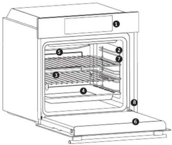
ACCESSORIES
- Control panel
- Shelf positions (lateral wire grid if included)
- Grids
- Trays
- Fan (if present)
- Oven door
-
Lateral wire grids (if present: only for flat cavity)
-
Serial number
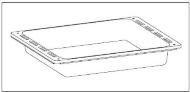
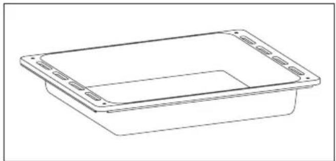
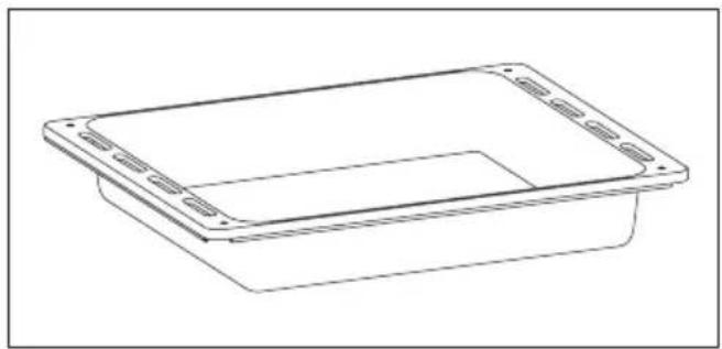
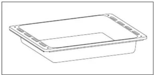
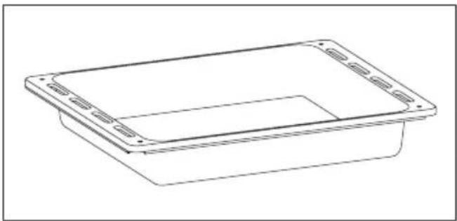
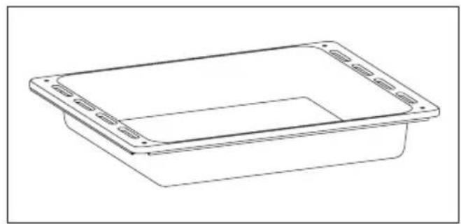
Drip tray

natural_image
Line drawing of a rectangular container with side slots and a recessed opening (no text or symbols)Collects residues that drip when cooking food on the grills.
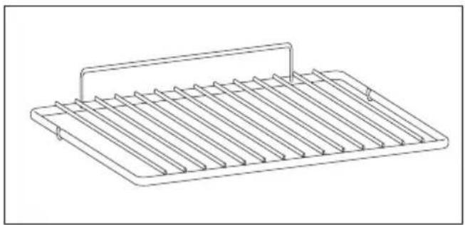
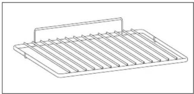
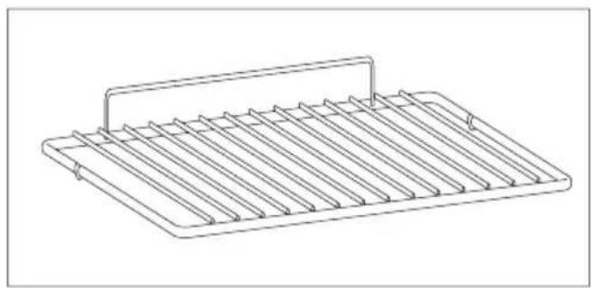
Metal grid
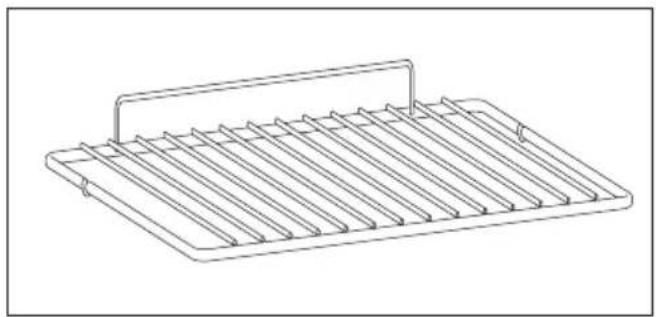
natural_image
Line drawing of a rectangular metal tray with vertical slats and a handle (no text or symbols)Holds baking trays and plates.
Lateral wire grids (only if present)
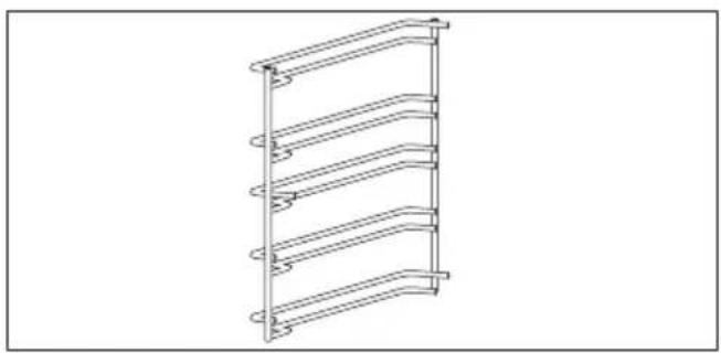
natural_image
Line drawing of a multi-tiered ladder structure with no text or symbolsLocated on both sides of the oven cavity, holds metal grills and drip pans.
First Use
PRELIMINARY CLEANING; Clean the oven before using for the first time. Wipe over external surfaces with a damp soft cloth. Wash all accessories and wipe inside the oven with a solution of hot water and washing up liquid. Set the empty oven to the maximum temperature and leave on for about 1 hour, this will remove any lingering smells of newness.
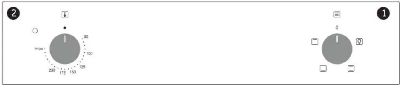
Display description
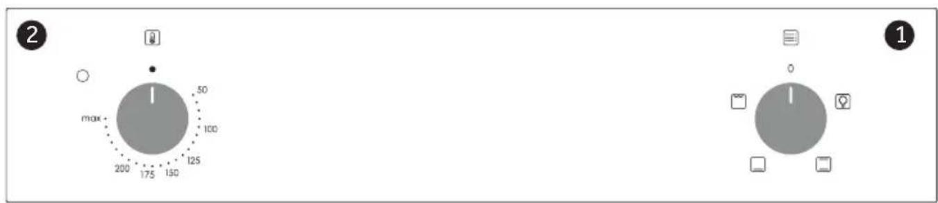
- Function selector knob
- Thermostat selector knob
Cooking Modes
| Symbol | T°C default | T°C range | Function |
 | LAMP: Turns on the oven light. | ||
 | 220 50 ÷ MAX | * CONVENTIONAL : Both top and bottom heating elements are used. Preheat the oven for about ten minutes. This method is ideal for all traditional roasting and baking. For seizing red meats, roast beef, leg of lamb, game, bread, foil wrapped food (papillotes), flaky pastry. Place the food and its dish on a shelf in mid position. | |
 | 210 50 ÷ MAX | BOTTOM HEATING: Using the lower element. Ideal for cooking all pastry based dishes. Use this for flans, quiches, tarts, pate and any cooking that needs more heat from below. | |
 | 230 50 ÷ MAX | GRILL: use the grill with the door closed.The top heating element is used alone and you can adjust the temperature. Five minutes preheating is required to get the elements red-hot.Success is guaranteed for grills, kebabs and gratin dishes. White meats should be put at a distance from the grill; the cooking time is longer, but the meat will be tastier. You can put red meats and fish fillets on the shelf with the drip tray underneath. | |
General notes on cleaning
The lifecycle of the appliance can be extended through regular cleaning. Wait for the oven to cool before carrying out manual cleaning operations. Never use abrasive detergents, steel wool or sharp objects for cleaning, so as to not irreparably damage the enamelled parts. Use only water, soap or bleach-based detergents (ammonia).
GLASS PARTS
It is advisable to clean the glass window with absorbent kitchen towel after every use of the oven. To remove more obstinate stains, you can use a detergent-soaked sponge, well wrung out, and then rinse with water.
OVEN WINDOW SEAL
If dirty, the seal can be cleaned with a slightly
damp sponge.
ACCESSORIES
Clean accessories with a wet, soapy sponge before rinsing and drying them: avoid using abrasive detergents.
DRIP PAN
After using the grill, remove the pan from the oven. Pour the hot fat into a container and wash the pan in hot water, using a sponge and washing-up liquid.
If greasy residues remain, immerse the pan in water and detergent. Alternatively, you can wash the pan in the dishwasher or use a commercial oven detergent. Never put a dirty pan back into the oven.
Maintenance
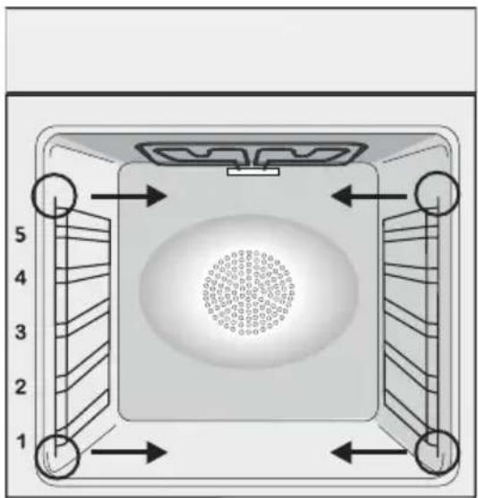
REMOVAL AND CLEANING OF THE SIDE RACKS
- Remove the wire racks by pulling them in the direction of the arrows (see below)
- To clean the wire racks either put them in the dishwasher or use a wet sponge, ensuring that they are dried afterwards.
- After the cleaning process install the wire racks in reverse order."
natural_image
Top-down diagram of a square room with numbered walls and central circular pattern (no text or symbols)CHANGING THE BULB
- Disconnect the oven from the mains supply.
- Undo the glass cover, unscrew the bulb and replace it with a new bulb of the same type.
- Once the defective bulb is replaced, replace the glass cover.
This product contains one or more light sources of energy efficiency class G (Lamp) /F (10 Led).
Waste management and environmental protection
natural_image
Symbol of a trash bin crossed with two crossed lines, no text or labels presentThis appliance is labelled in accordance with European Directive 2012/19/EU regarding electric and electronic appliances (WEEE). The WEEE contain both polluting substances (that can have a negative effect on the environment) and base elements (that can be reused). It is important that WEEE undergo specific treatments to correctly remove and dispose of the pollutants and recover all the materials. Individuals can play an important role in ensuring that the WEEE do not become an environmental problem; it is essential to follow a few basic rules:
- the WEEE should not be treated as domestic waste;
- the WEEE should be taken to dedicated collection areas managed by the town council or a registered company.
In many countries, domestic collections may be available for large WEEEs. When you buy a new appliance, the old one can be returned to the vendor who must accept it free of charge as a one-off, as long as the appliance is of an equivalent type and has the same functions as the purchased appliance.
SAVING AND RESPECTING THE ENVIRONMENT
Where possible, avoid pre-heating the oven and always try to fill it. Open the oven door as infrequently as possible, because heat from the cavity disperses every time it is opened. For a significant energy saving, switch off the oven between 5 and 10 minutes before the planned end of the cooking time, and use the residual heat that the oven continues to generate. Keep the seals clean and in order, to avoid any heat dispersal outside of the cavity. If you have an electric contract with an hourly tariff, the “delayed cooking” programme makes energy saving more simple, moving the cooking process to start at the reduced tariff time slot.
Troubleshooting
| Problem Possible cause Solution | ||
| the oven does not heat up | The clock is not set Set the clock | |
| The oven does not heat up | A cooking function and temperature has not been set | Ensure that the necessary settings are correct |
| No reaction of the touch user interface | Steam and condensation on the user interface panel | Clean with a microfiber cloth the user interface panel to remove the condensation layer |
ACCESSOIRES
natural_image
Line drawing of a rectangular container with side slots and a recessed top (no text or symbols)natural_image
Line drawing of a multi-tiered rack or shelf structure with curved supports (no text or symbols)natural_image
Line drawing of a rectangular metal tray with vertical slats and a handle (no text or symbols)natural_image
Top-down diagram of a square appliance with numbered corners and internal structure (no text or symbols)REEMPLACEMENT DE L'AMPOULE
natural_image
Symbol of a trash bin crossed with two crossed lines and a solid black rectangle below (no text or labels)Dépannage
ACCESSORI
natural_image
Line drawing of a rectangular container with side flanges and a recessed top (no text or symbols)natural_image
Line drawing of a multi-tiered ladder structure with curved bracing (no text or symbols)natural_image
Line drawing of a rectangular metal tray with vertical slats and a handle (no text or symbols)natural_image
Top-down diagram of a square appliance with internal fan and circular vent, no text or symbols presentnatural_image
Simple line drawing of a trash bin with crossed lines and a solid black rectangle below (no text or symbols)ZUBEHÖR
natural_image
Line drawing of a rectangular container with side flanges and a central slot (no text or symbols)natural_image
Line drawing of a rectangular metal tray with vertical slats and a handle (no text or symbols)natural_image
Line drawing of a multi-tiered ladder structure (no text or symbols)natural_image
Simple diagram with a central circle and surrounding icons (no text or labels)1
natural_image
Top-down diagram of a square room with numbered walls and central circular pattern (no text or symbols)WECHSELN DER GLÜHBIRNE
natural_image
Symbol of a trash bin crossed with two crossed lines, no text or labels presentACCESORIOS
Bandeja de goteo
natural_image
Line drawing of a rectangular container with side flanges and a recessed top (no text or symbols)natural_image
Line drawing of a multi-tiered ladder structure with no text or symbolsnatural_image
Line drawing of a rectangular metal tray with vertical slats and a handle (no text or symbols)natural_image
Top-down diagram of a square room with numbered walls and central circular pattern (no text or symbols)natural_image
Symbol of a trash bin with crossed lines indicating no waste or discharge (no text or labels)ACCESSOIRES
natural_image
Line drawing of a rectangular container with side flanges and a recessed top (no text or symbols)natural_image
Line drawing of a rectangular metal tray with vertical slats and a handle (no text or symbols)natural_image
Line drawing of a multi-tiered shelf structure with curved supports (no text or symbols)natural_image
Top-down diagram of a square appliance with internal fan and circular vent, no text or symbols presentHET LAMPJE VERVANGEN
natural_image
Symbol of a trash bin with crossed lines indicating no waste or discharge (no text or labels)ACESSÓRIOS
natural_image
Line drawing of a rectangular plastic container with mounting holes (no text or symbols)natural_image
Line drawing of a multi-tiered ladder structure (no text or symbols)natural_image
Line drawing of a rectangular metal tray with vertical slats and a handle (no text or symbols)natural_image
Top-down diagram of a square room with circular vent and directional arrows indicating layout (no text or symbols)SUBSTITUIR A LÂMPADA
natural_image
Symbol of a trash bin crossed with two crossed lines, no text or labels presentEN If the furniture is coverage with a bottom at the back part, provide an opening for the power supply cable.
EN If the mounting of the plinth does not allow air circulation, it is necessary to create an opening of 500x10 mm or the same surface in 5000 mm ^2 .
EN If the oven does not have a cooling fan, create an opening 460 mm x 15 mm
natural_image
Simple line drawing of a calendar with two dots above it, no text or symbols presentORKAITÉ
CEPEŠKRĀSNIS
AHJUD
Naudojimo instrukcija
Lietošanas instrukcija
Kasutusjuhend
Turinys
REIKMENYS
natural_image
Line drawing of a rectangular plastic container with side flanges and a recessed opening (no text or symbols)natural_image
Line drawing of a rectangular metal tray with vertical slats and a handle (no text or symbols)natural_image
Line drawing of a multi-tiered rack or shelf structure with curved bands (no text or symbols)natural_image
Gray circular icon with a central 'I' and surrounding icons (no text or symbols)
- Funkciju selektoriaus rankenėlė
- Termostato rankenèlè
Gaminimo režimai
natural_image
Top-down diagram of a square room with a central circular pattern and numbered arrows indicating directional flow (no text or symbols)LEMPUTÈS PAKEITIMAS
natural_image
Symbol of a trash bin crossed with two crossed lines, no text or labels presentPIEDERUMI
natural_image
Line drawing of a rectangular plastic container with mounting holes (no text or symbols)natural_image
Line drawing of a rectangular metal tray with vertical slats and a handle (no text or symbols)natural_image
Line drawing of a multi-tiered ladder structure (no text or symbols)natural_image
Gray circular icon with five small icons surrounding it, no text or symbols present.
2
natural_image
Top-down diagram of a square-shaped device with internal circular pattern and numbered arrows indicating orientation (no text or symbols)SPULDZES NOMAINA
natural_image
Symbol of a trash bin crossed with two crossed lines, no text or labels presentTARVIKUD
natural_image
Line drawing of a rectangular plastic container with mounting flanges (no text or symbols)Metallrest
natural_image
Line drawing of a rectangular metal tray with vertical slats and a handle (no text or symbols)natural_image
Line drawing of a multi-tiered ladder structure (no text or symbols)natural_image
Gray circular icon with five small icons surrounding it, no text or symbols present.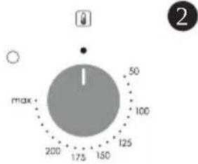
natural_image
Top-down diagram of a square appliance with internal components and directional arrows indicating flow or movement (no text or symbols)VALGUSTUSPIRNI VAHETAMINE
natural_image
Simple line drawing of a trash bin with crossed lines indicating no waste or plastic (no text or symbols)- SAFETY INSTURUCTIONS
- INSTRUCTIONS FOR THE INSTALLER
- BUILDING IN
- SUITABLE LOCATION
- ELECTRICAL CONNECTION (FOR U.K. ONLY)
- Warning - this appliance must be earthed
- CONNECT TO SPUR TERMINAL
- ELECTRICAL CONNECTION
- GAS CONNECTION
- ADAPTING THE HOB TO DIFFERENT TYPES OF GAS
- REGULATING THE MINIMUM FLAME
- USE OF HOB - USER INSTRUCTIONS
- GENERAL ADVISE
- MAINTENANCE AND CLEANING
- Chromed grids and burners
- AFTERCARE
- PROTECTION OF THE ENVIRONMENT
- SAVING AND RESPECTING THE ENVIRONMENT
- DECLARATION OF COMPLIANCE
- CONSIGNES DE SÉCURITÉ
- DÉCLARATION DE CONFORMITÉ
- POUŽITÍ PLYNOVÉHO HOŘÁKU
- UŻYWANIE PALNIKÓW GAZOWYCH
- CANDY
- GARANTI BELGESI
- ANKASTRE OCAK
- NAVODILA ZA VARNO UPORABO
- UPORABA GORILNIKOV
- COMO UTILIZAR O QUEIMADOR DE GÁS
- A GÁZÉGŐ HASZNÁLATA
- UTILIZAREA ARZĂTOARELOR
- POUŽITIE PLYNOVÉHO HORÁKA
- UPOTREBA PLINSKOG PLAMENIKA
- GAASIPÕLETI KASUTAMINE
- KESKKONNA SÄÄSTMINE JA AUSTAMINE
- DUJU DEGIKLIO NAUDOJIMAS
- GB - IE
- FR
- WYMIANA ŻARÓWKI
- VÝMĚNA ŽÁROVKY
- ZAMENJAVA ŽARNICE
- Prvé použitie
- PREDČISTENIE
- ZMENA ŽIAROVKY
- СМЯНА НА КРУШКАТА
- PRETHODNO ČIŠĆENJE
- ZAMJENA ŽARULJICE IZ SVJETILJKE
- Prva upotreba
- Opis komandne table
- Generalne napomene o čišćenju
- STAKLENI DELOVI
- GUMA RERNE
- ZAMENA SIJALICA
- ČUVANJE I POŠTOVANJE ŽIVOTNE SREDI- NE
- ACCESORII
- SCHIMBAREA BECULUI
- ЗАМЕНА ЛАМПОЧКИ
- КЕРЕК-ЖАРАКТАР
- ЗАМИНА ЛАМПИ
- Safety Indications
- General Instructions
- Electrical Safety
- CONNECTION
- WARNING
- Recommendations
- Installation
- Product description
- First Use
- Display description
- General notes on cleaning
- GLASS PARTS
- OVEN WINDOW SEAL
- ACCESSORIES
- DRIP PAN
- Maintenance
- REMOVAL AND CLEANING OF THE SIDE RACKS
- CHANGING THE BULB
- Waste management and environmental protection
- ACCESSOIRES
- REEMPLACEMENT DE L'AMPOULE
- ACCESSORI
- WECHSELN DER GLÜHBIRNE
- HET LAMPJE VERVANGEN
- SUBSTITUIR A LÂMPADA
- Naudojimo instrukcija
- Lietošanas instrukcija
- Kasutusjuhend
- Turinys
- Gaminimo režimai
- LEMPUTÈS PAKEITIMAS
- SPULDZES NOMAINA
- VALGUSTUSPIRNI VAHETAMINE
Brand : CANDY
Model : PCI30BCVW6BB
Category : Oven