SRQ24U - Server Tripp Lite - Free user manual and instructions
Find the device manual for free SRQ24U Tripp Lite in PDF.

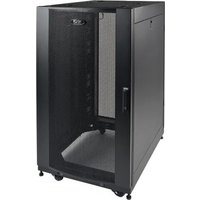
| Product Type | Silent rack enclosure with noise attenuation |
| Model | SRQ24U |
| Mounting Capacity | 24U |
| Static Load Capacity | 453.5 kg (1000 lb) |
| Caster Load Capacity | 453.5 kg (1000 lb) |
| Dimensions (W x H x D) | 762 x 1246 x 1186 mm (30 x 49 x 46.7 in) |
| Net Weight | 135 kg (297 lb) |
| Shipping Weight | 150 kg (330 lb) |
| Casters | Yes, for position adjustments only |
| Doors | Lockable front and rear doors with noise-dampening foam panels |
| Side Panels | With sound-dampening foam, non-removable |
| Ventilation | Two sets of vertical fans for hot air exhaust |
| Power | Integrated power bar, 15 A max, 120 V AC |
| Warranty | 5-year limited |
| Maintenance | Clean with a dry cloth; do not use liquids |
| Safety | Do not overload power bar; grounding required; multiple person handling |
| Included | Keys, mounting hardware (60 screws, cage nuts, washers), documentation |
| Mounting Rail Adjustment | In 9.5 mm increments, depth from 406.5 to 765 mm |
| Operating Temperature | Controlled indoor environment, protected from moisture and extremes |
| Noise Attenuation | Integrated foam panels in doors, side panels, top, and bottom |
Frequently Asked Questions - SRQ24U Tripp Lite
User questions about SRQ24U Tripp Lite
0 question about this device. Answer the ones you know or ask your own.
Ask a new question about this device
Download the instructions for your Server in PDF format for free! Find your manual SRQ24U - Tripp Lite and take your electronic device back in hand. On this page are published all the documents necessary for the use of your device. SRQ24U by Tripp Lite.
USER MANUAL SRQ24U Tripp Lite
Quiet Rack Enclosure with Sound Suppression
Models: SRQ18U, SRQ24U
Important Safety Instructions 2 Overview 2
Feature Identification 3
Enclosure Installation 4 Preparation 4
Unpacking 4
Placement 5
Ground Connection 6
Enclosure Configuration 6
Adjusting Mounting Rails 6
Equipment Installation 7 Installing or Removing Cage Nuts 7
Operation 8
Specifications 8
Storage and Service 8
Warranty and Product Registration 9
Espanol 10
Français 19
PROTECT YOUR INVESTMENT!
Register your product for quicker service and ultimate peace of mind.
You could also win an ISOBAR6ULTRA surge protector—a $100 value!
www.triplite.com/warranty


Manufacturing Excellence.
1111 W. 35th Street, Chicago, IL 60609 USA • www.triplite.com/support
Copyright © 2018 Tripp Lite. All trademarks are the sole property of their respective owners.
Important Safety Instructions
SAVE THESE INSTRUCTIONS
All sections of this manual contain instructions and warnings that should be followed during the installation and use of the SmartRack Enclosures described in this manual. Read all instructions and warnings thoroughly before attempting to move, install or use the SmartRack Enclosures described in this manual. Failure to comply will create a risk of personal injury and property damage and may invalidate the warranty.
- Keep the enclosure in a controlled indoor environment, away from moisture, temperature extremes, flammable liquids and gasses, conductive contaminants, dust and direct sunlight.
- Leave adequate space at the front and rear of the enclosure for proper access. Do not block, cover or insert objects into the external ventilation openings of the enclosure.
The enclosure is extremely heavy. Use caution when handling the enclosure. Do not attempt to unpack, move or install it unassisted. Use a mechanical device such as a forklift or pallet jack to move the enclosure in the shipping container. - Do not place any object on the enclosure, especially containers of liquid, and do not attempt to stack the enclosures.
- Inspect the shipping container and the enclosure for shipping damage. Do not use the enclosure if it is damaged.
- Leave the enclosure in the shipping container until it has been moved as close to the final installation location as possible. The casters are designed for minor position adjustments within the final installation area only. The casters are not designed for moving the enclosure over longer distances.
- Install the enclosure in a structurally sound area with a level floor that is able to bear the weight of the enclosure, all equipment that will be installed in the enclosure and any other enclosures and/or equipment that will be installed nearby.
- Do not push the enclosure from the side panels to move it. Pushing from the side panels will cause a tipping hazard.
- When rolling the enclosure on its casters, always push it from behind, never pull it toward you.
- A rolling enclosure can cause personal injury and property damage if not properly supervised. If rolling the enclosure down a ramp is required, use extreme caution. Do not attempt to use ramps that have a slope steeper than 1:12.
- Use caution when cutting packing materials. The enclosure could be scratched, causing damage not covered by the warranty.
- Save all packing materials for later use. Repacking and shipping the enclosure without the original packing materials may cause product damage that will void the warranty.
- Do not re-ship the enclosure with additional equipment. The combined weight of the enclosure and installed equipment must not exceed the load capacity of the pallet. Tripp Lite is not responsible for any damage that occurs during re-shipment.
- Use of this equipment in life support applications where failure of this equipment can reasonably be expected to cause the failure of the life support equipment or to significantly affect its safety or effectiveness is not recommended.
Overview
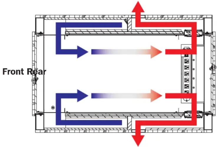
The SRQ18U/SRQ24U SmartRack Quiet Rack Cabinet with Sound Suppression uses foam sound-dampening panels built into its doors, side panels, and top and bottom panels to reduce external acoustic levels caused by network equipment. A unique airflow design draws in cool air through its bottom panel intake, passes it horizontally through the enclosure, and uses internal fans to push warm air out through two chambers located on its side panels. SRQ18U/SRQ24U enclosures ship fully assembled for quick and easy deployment. All standard 19-inch rack-mount equipment is compatible with this unit.
Feature Identification
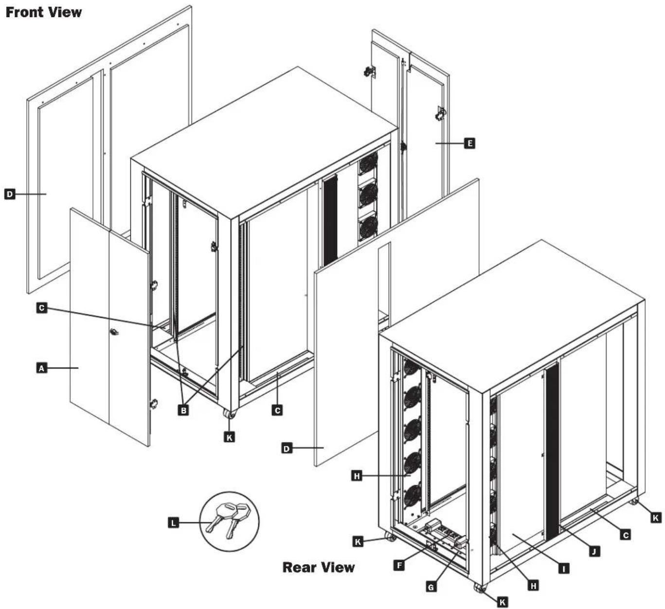
Front View
A Locking Front Doors with Foam Sound-Dampening Baffles
8 Mounting Rails (Provide horizontal and vertical mounting points for equipment.)
Cool-Air Intakes
Side Panels with Foam Sound-Dampening Baffles
Note: Side panels are not removable.
Locking Rear Doors with Foam Sound-Dampening Baffles
Power Strip (for use with Exhaust Fans)
Brush Strip Plate
Exhaust Fans
Hot Air Chambers
Hot Air Exhaust Vents
K Casters
Keys
Not Shown: Mounting hardware, documentation, shipping brackets and other shipping materials.
Enclosure Installation

Caution! Read All Instructions andWarnings Before Installation!

WARNING: The rack enclosure is extremely heavy. Do not attempt to unpack, move or install the enclosure without assistance. Until it has been properly installed and stabilized, the enclosure is prone to tipping and could cause property damage and/or personal injury. Use extreme caution when handling the enclosure and be sure to follow all handling and installation instructions. Do not attempt to install equipment without first stabilizing the enclosure.
Preparation
The enclosure must be installed in a structurally sound area with a level floor that is able to bear the weight of the enclosure, all the equipment that will be installed in the enclosure and any other enclosures and/or equipment that will be installed nearby. Before unpacking the enclosure, you should transport the shipping container closer to the final installation location to minimize the distance you will need to move the unit after the protective packaging has been removed. If you plan to store the enclosure for an extended period before installation, follow the instructions in the Storage and Service section.
You need several tools (user-supplied):
13 mm Open-end Wrench
18 mm Open-end Wrench
Utility Blade
Carpenter's Level
Phillips-head Screwdriver
5/32" Allen Wrench
You also need the following hardware (included):
(60) Phillips-head Mounting Screws (M6 x 5/8")
(60) Cage Nuts (M6)
(60) Nylon Cup Washers
Unpacking
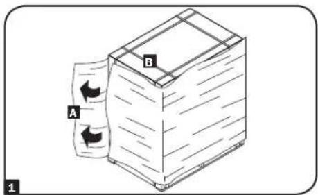
1 Confirm the shipping container is upright and stable, then use a utility blade to cut the shrink-wrap A. Apply the utility blade directly over one of the corners (a corner protector is located underneath the cardboard packing materials) to prevent the utility blade from scratching the enclosure or cutting the heavy protective plastic bag beneath the shrink-wrap. Cut and remove the plastic straps surrounding the cardboard packaging F. WARNING: Do not scratch the enclosure or cut the heavy plastic bag beneath the cardboard packaging. Do not push or pull the enclosure while unpacking.
2 Remove the cardboard packing materials covering the enclosure. Save all packing materials (including the pallet) for later use unless you are certain they will not be required. The packing materials are recyclable.
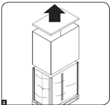
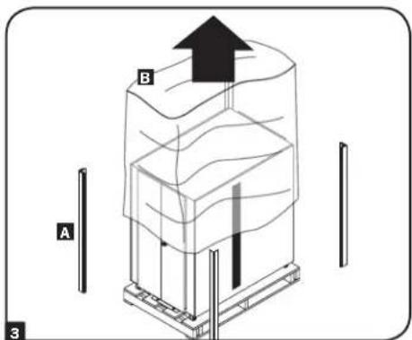
3 Remove the corner protectors A, then remove the heavy plastic bag surrounding the enclosure B. Examine the enclosure for any damage or loose parts. Confirm that all parts are present. If anything is missing or damaged, contact Tripp Lite for assistance. Do not attempt to use the enclosure if it has been damaged.
Enclosure Installation
Unpacking (continued)
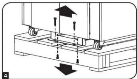
Use a 13 mm open-end wrench to remove the shipping brackets. Be extremely careful, as the enclosure could shift unexpectedly after bracket removal. Save the brackets and bracket hardware for later use.
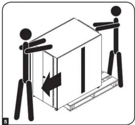
5 Position at least one person at the front of the enclosure and one person at the rear of the enclosure. Slowly push the enclosure toward the back of the shipping pallet until all four casters go over the edge of the pallet and touch the floor. WARNING: Use at least one assistant when removing the enclosure from the pallet. Be extremely careful when moving the enclosure.
Placement
WARNING: Install the enclosure in a structurally sound area with a level floor that is able to bear the weight of the enclosure, all equipment installed in the enclosure, and any other enclosures and/or equipment installed nearby.
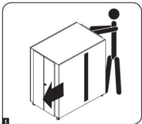
Use the casters to move the enclosure for a short distance over a level, smooth, stable surface by pushing it from the front or rear (not the side panels). Do not attempt to roll the enclosure over long distances. The enclosure should be moved close to its installation location inside its shipping container before it is unpacked. (Use a forklift or pallet jack to move the shipping container.) Warning: Do not push or pull the enclosure at the side panels or pull the enclosure toward you.
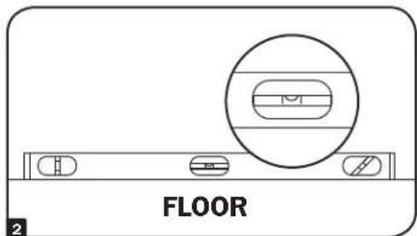
2 After the enclosure has been moved to the installation location, use a carpenter's level to check the slope of the floor. If the floor slopes more than 1% , choose an alternate installation site.
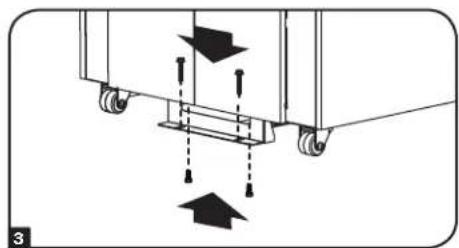
(Optional) To provide an additional measure of stability, you can attach a shipping bracket to the front end of the unit using the hardware that secured the enclosure to the shipping pallet. Use a 13 mm open-end wrench to connect the bracket to the bracket mounting points on the front of the enclosure. Then attach the bracket to secure mounting points in the floor using user-supplied hardware or Tripp Lite's SmartRack Bolt-Down Kit (model: SRBOLTDOWN).
Note: Do not mount the bracket to the rear end of the unit. Doing so will obstruct the brush strip plate and prohibit the ability to run cables through the bottom panel.
Enclosure Installation
Ground Connection
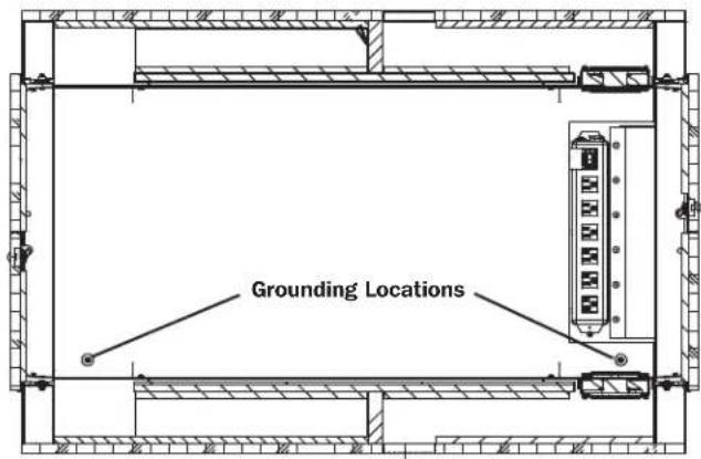
All enclosure components are grounded to the enclosure frame. Use the ground points located at the front or rear of the enclosure to connect an 8 AWG (3.264 mm) wire to your facility's earth ground connection. WARNING: Attach each enclosure to earth ground separately. Do not use the enclosure without an earth ground connection.
Enclosure Configuration
Adjusting Mounting Rails
WARNING: Do not attempt to adjust rails without assistance. Do not attempt to adjust rails while equipment is installed in the enclosure. Do not attempt to use rails without screws installed (two per rail).
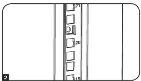
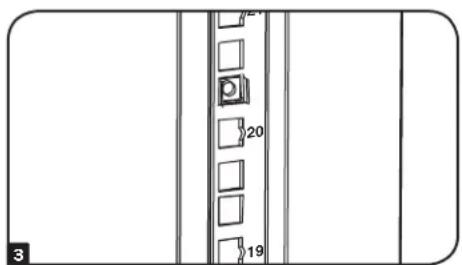
The two mounting rails are pre-installed to the maximum front-to-rear rail distance of 30 inches (765 mm). This setting supports equipment depths up to 45 inches (1143 mm) maximum. Do not adjust the mounting rails unless your equipment requires different front or rear rail settings. The front and rear rails can be adjusted independently in 3/8-inch (9.5 mm) increments for front-to-rear rail distances of 16 inches (406.5 mm) to 30 inches (765 mm).
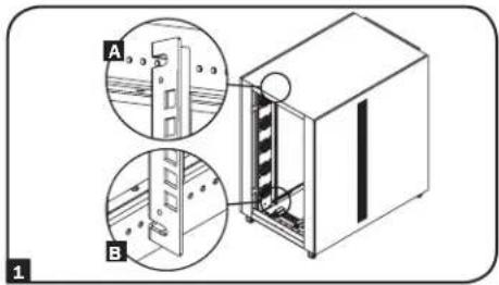
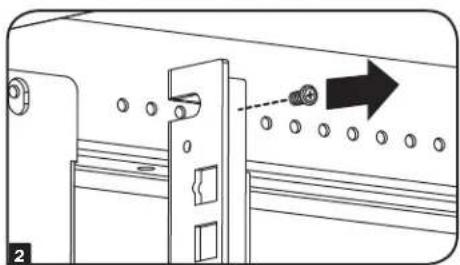
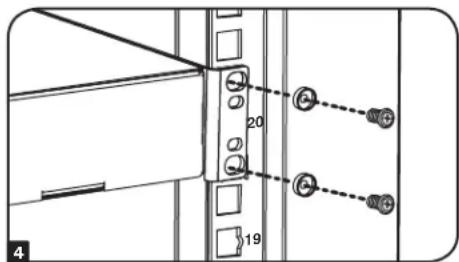
Each rail is connected to the enclosure with two screws: one at the upper beam A and one at the lower beam B.
2 Remove the screws fastening each of the rear mounting rails to the enclosure. (If adjustment of the front rails is required, you can also remove the screws from the front rails.)
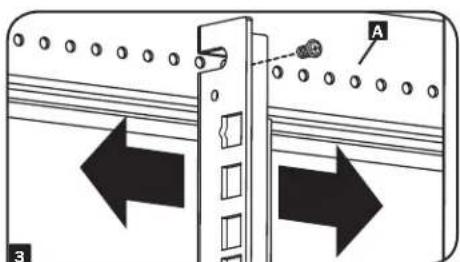
3 Slide the mounting rails to the desired depth and reattach them using the screws you removed in Step 2. The rail attachment points are numbered A to help you align each pair of rails at the same depth.
Equipment Installation
WARNING: Do not install equipment until you have stabilized the enclosure. Install heavier equipment first and install it toward the bottom of the enclosure. Install equipment starting from the bottom of the enclosure and proceeding toward the top of the enclosure - never the reverse. If using sliding equipment rails, be careful when extending the rails. Do not extend more than one set of sliding equipment rails at one time. Avoid extending sliding equipment rails near the top of the enclosure.
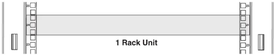
Note: The square holes at the middle of each rack unit are numbered and also include a small notch to aid identification. A single rack unit includes the space occupied by the numbered hole and the holes directly above and below.
Installing or Removing Cage Nuts
WARNING: The flanges of the cage nuts should engage the sides of the square opening in the rail, not the top and bottom. Follow the instructions in your equipment documentation to ensure proper installation of your equipment.
Installing Cage Nuts
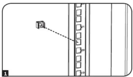
1 Locate the numbered square openings in the mounting rails where you plan to install your equipment. You will install cage nuts (included) into the square openings in order to provide an attachment point for the mounting screws (included).
Note: Consult your equipment documentation to determine how many cage nuts will be required and where they will need to be installed.
2 From the inside of the mounting rail, insert one of the flanges of the cage nut through the square opening. Press it against the side of the square opening. Each flange should engage one side of the square opening, not the top or bottom.
3 Compress the cage nut at the sides slightly to allow the remaining flange to fit through the square opening. When the cage nut is properly installed, both flanges will protrude through the square opening and will be visible on the outer surface of the mounting rail. Repeat steps 1-3 until all required cage nuts are installed.
4 After installing the required cage nuts, use the included mounting screws and cup washers to secure your equipment to the rack rail. Place the cup washers between the screws and the equipment mounting brackets.
Note: Your equipment may also include mounting hardware. Read the mounting instructions that came with your equipment before installing your equipment.
To Remove Cage Nuts, Reverse Steps 1-3
Note: You may wish to use a cage nut tool (user-supplied) to aid cage nut installation and removal.
Operation
The SRQ18U/SRQ24U uses two sets of vertically mounted fans to push warm air generated from equipment into the warm air chambers and side exhaust panels.
Connect Fans to the Power Strip
Plug each fan unit into the power strip located on the bottom panel at the rear of the unit. The remaining outlets are available for plugging in accessories or additional fan units (sold separately).
IMPORTANT: DO NOT OVERLOAD THE POWER STRIP. The power strip can accommodate a total equipment load up to 15A (whether plugged in to a single outlet or spread out over multiple outlets). If the circuit breaker trips, outlets will cease to provide power. Reduce the load on the power strip down to its 15A rating by unplugging excess equipment, then depress the circuit breaker button to reset.
Connect the Power Strip to an AC Power Line
Plug the power strip directly into a 3-wire grounded, 120V AC outlet.
Turn Power Switch ON
To provide power to the fans and any additional equipment, turn on the power switch.
Specifications
| Load Capacity Unit D | Dimensions Shipping Dimensions | |||||||||
| Model Static Rolling | Height Width | Depth Weight | Height Width | Depth Weight | ||||||
| SRQ18U 750 lb. | (340 kg) | 750 lb. (340 kg) | 38.6 in. (978 mm) | 30 in. (762 mm) | 46.7 in. (1186 mm) | 242 lb. (110 kg) | 44 in. (1092 mm) | 32 in. (813 mm) | 48.7 in. (1237 mm) | 271 lb. (123 kg) |
| SRQ24U 1000 lb. | (453.5 kg) | 1000 lb. (453.5 kg) | 49 in. (1246 mm) | 30 in. (762 mm) | 46.7 in. (1186 mm) | 297 lb. (135 kg) | 54.4 in. (1379 mm) | 32 in. (812 mm) | 48.7 in. (1237 mm) | 330 lb. (150 kg) |
Storage and Service
Storage
The enclosure should be stored in a controlled indoor environment, away from moisture, temperature extremes, flammable liquids and gasses, conductive contaminants, dust and direct sunlight. Store the enclosure in its original shipping container if possible.
Service
Your Tripp Lite product is covered by the warranty described in this manual. A variety of Extended Warranty and On-Site Service Programs are also available from Tripp Lite. For more information on service, visit www.triplite.com/support. Before returning your product for service, follow these steps:
- Review the installation and operation procedures in this manual to insure that the service problem does not originate from a misreading of the instructions.
- If the problem continues, do not contact or return the product to the dealer. Instead, visit www.triplite.com/support.
- If the problem requires service, visit www.triplite.com/support and click the Product Returns link. From here you can request a Returned Material Authorization (RMA) number, which is required for service. This simple on-line form will ask for your unit's model and serial numbers, along with other general purchaser information. The RMA number, along with shipping instructions will be emailed to you. Any damages (direct, indirect, special or consequential) to the product incurred during shipment to Tripp Lite or an authorized Tripp Lite service center is not covered under warranty. Products shipped to Tripp Lite or an authorized Tripp Lite service center must have transportation charges prepaid. Mark the RMA number on the outside of the package. If the product is within its warranty period, enclose a copy of your sales receipt. Return the product for service using an insured carrier to the address given to you when you request the RMA.
Warranty and Product Registration
5-Year Limited Warranty
h should prove defective in material or workmanship within that period. Seller will repair or replace the product, in its sole discretion.
THIS WARRANTY DOES NOT APPLY TO NORMAL WEAR OR TO DAMAGE RESULTING FROM ACCIDENT, MISUSE, ABUSE OR NEGLECT. SELLER MAKES NO EXPRESS WARRANTY OTHER THAN THE WARRANTY EXPRESSLY SET FORTH HEREIN. EXCEPT TO THE EXTENT PROHIBITED BY APPLICABLE LAW, ALL IMPLIED WARRANTY, INCLUDING ALL WARRANTY OF MERCHANTABILITY OR FITNESS, ARE LIMITED IN DURATION TO THE WARRANTY PERIOD SET FORTH ABOVE; AND THIS WARRANTY EXPRESSLY EXCULES ALL INCIDENTAL AND CONSEQUENTIAL DAMAGES. (Some states do not allow limitations on how long an implied warranty lasts, and some states do not allow the exclusion or limitation of incidental or consequential damages, so the above limitations or exclusions may not apply to you. This warranty gives you specific legal rights, and you may have other rights which vary from jurisdiction to jurisdiction).
WARNING: The individual user should take care to determine prior to use whether this device is suitable, adequate or safe for the use intended. Since individual applications are subject to great variation, the manufacturer makes no representation or warranty as to the suitability or fitness of these devices for any specific application.
Product Registration
Visit www.triplite.com/warranty today to register your new Tripp Lite product. You'll be automatically entered into a drawing for a chance to win a FREE Tripp Lite product*
- No purchase necessary. Void where prohibited. Some restrictions apply. See Web site for details.
Regulatory Compliance Identification Numbers
For the purpose of regulatory compliance certifications and identification, your Tripp Lite product has been assigned a unique series number. The series number can be found on the product nameplate label, along with all required approval markings and information. When requesting compliance information for this product, always refer to the series number. The series number should not be confused with the marketing name or model number of the product.
Tripp Lite has a policy of continuous improvement. Product specifications are subject to change without notice.
Note on Labeling
This symbol is used on the product: Ground Connection


1111 W. 35th Street, Chicago, IL 60609 USA · www.triplite.com/support
1111 W. 35th Street, Chicago, IL 60609 USA • www.triplite.com/support
1111 W. 35th Street, Chicago, IL 60609 USA • www.triplite.com/support