
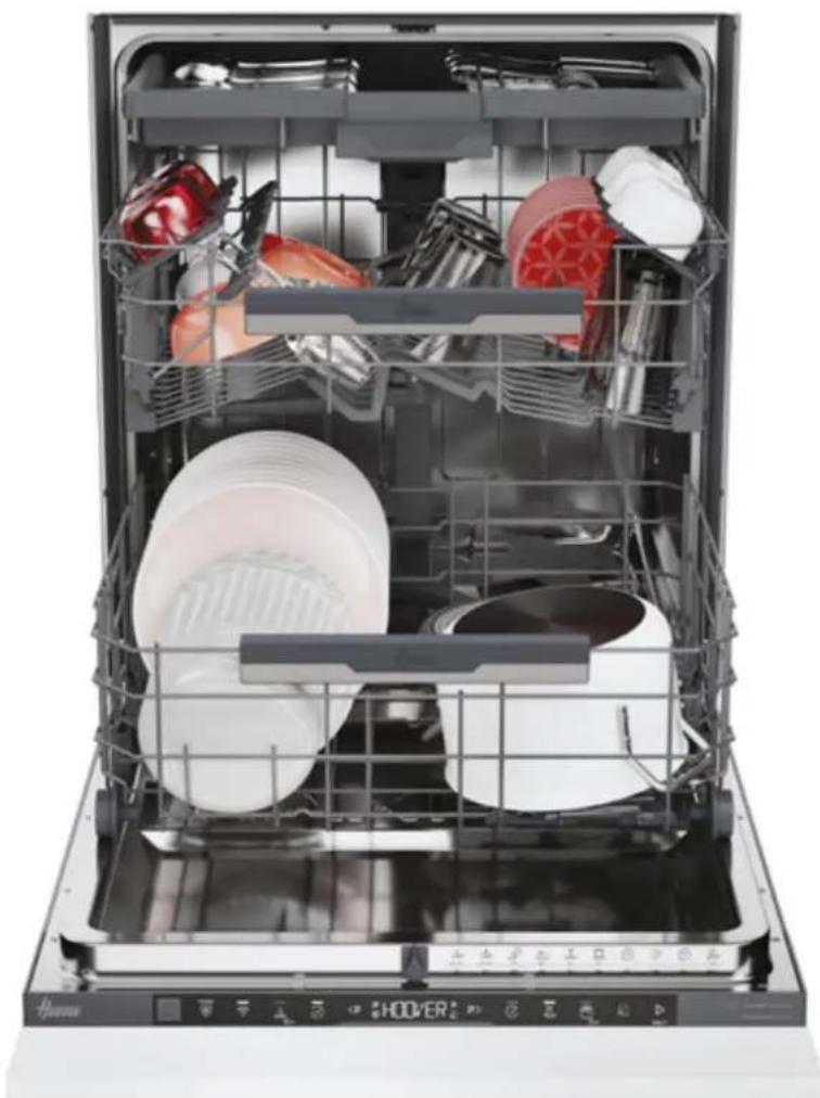
HI 5C6F0S-80 - Dishwasher HOOVER - Free user manual and instructions
Find the device manual for free HI 5C6F0S-80 HOOVER in PDF.
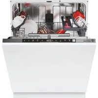


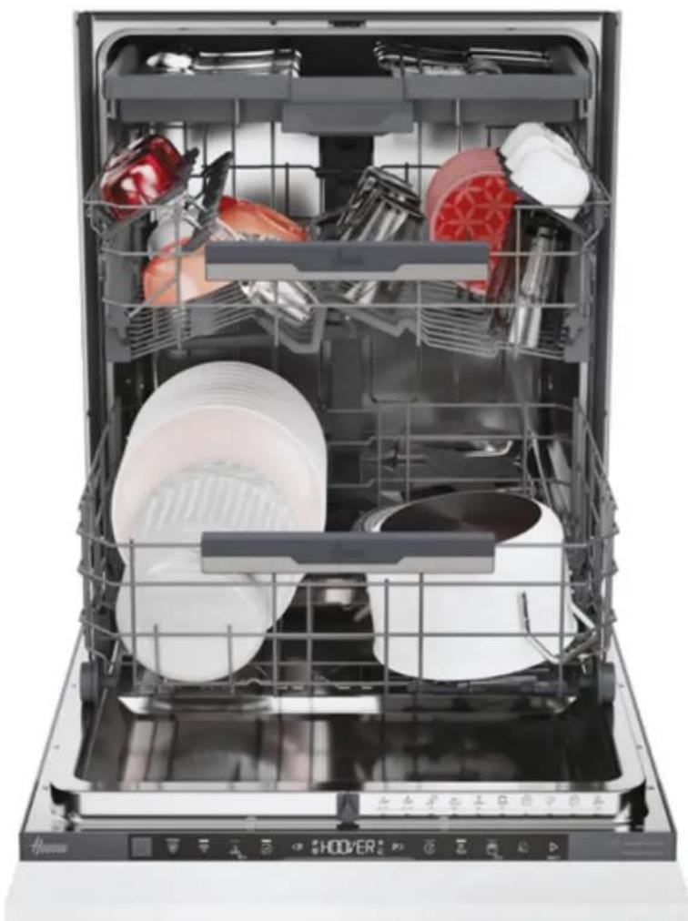
| Product type | Built-in dishwasher |
| Brand | Hoover |
| Model | HI 5C6F0S-80 |
| Dimensions (W x D x H) | 598 x 555 x 818-898 mm (adjustable height) |
| Product weight | Approximately 40 kg (standard estimate) |
| Power supply | 230 V / 50 Hz, power cable ~1350 mm |
| Rated power | 1900 W (standard estimate) |
| Required water pressure | 0.08 - 1 MPa |
| Water inlet | Hose ~1500 mm, connection Ø 15 mm |
| Water outlet | Hose ~1700 mm, diameter Ø 20-28 mm |
| Rated capacity | 12 place settings (standard estimate) |
| Minimum built-in height | 820 mm |
| Maximum built-in height | 900 mm |
| Maximum door panel weight | 9 kg |
| Door panel thickness | 16-22 mm |
| Safety device | Automatic overflow protection |
| Installation | Built-in, requires a qualified technician |
| Included accessories | Screws, anti-vapor strip, drilling template |
| Energy class | Not specified (estimated class A or higher) |
| Noise level | Not specified (estimated 44-49 dB) |
Frequently Asked Questions - HI 5C6F0S-80 HOOVER
User questions about HI 5C6F0S-80 HOOVER
0 question about this device. Answer the ones you know or ask your own.
Ask a new question about this device
Download the instructions for your Dishwasher in PDF format for free! Find your manual HI 5C6F0S-80 - HOOVER and take your electronic device back in hand. On this page are published all the documents necessary for the use of your device. HI 5C6F0S-80 by HOOVER.
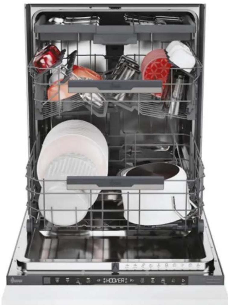
USER MANUAL HI 5C6F0S-80 HOOVER
DOUBLE MOVEMENT HINGES
PERFORMANCE THAT LASTS

EN | IT | FR | DE | ES | GR | NL | PT | SK | PL | CZ | RO | HU
SL | SR | LT | EE | LV | BG | HR | DA | FI | NO | SV | UA | TR
WELCOME
This installation manual is intended for kitchen manufacturers who will accommodate these products. To ensure safety and achieve the best results, carefully read this manual, including the safety instructions, and keep it for future reference. Before proceeding with installation, note the serial number, as it may be needed in case of repairs. Check for any damage during transport and consult a technician if in doubt before use. Always keep all packaging materials out of reach of children.
NOTE: The features and images contained in this document are for reference only and may change without notice.
Index
1 safety notices for installation
2 Where to install the dishwasher p.3
3 Dishwasher dimensions p.4-5
4 Step-by-step installation video p.6
5 installation tools p.6
6 Built-in dimensions p.7
7 Instructions for dishwasher installation p.8 - 17
7.1 Installation of the anti-steam strip 7.2 Height adjustment 7.3 Adjustment of the rear foot 7.4 Adjustment of the front feet height 7.5 Tilt adjustment 7.6 Insertion into the built-in compartment 7.7 Fixing the front feet 7.8 Preparation of the panel 7.9 Installation of the panel 7.10 Fixing the machine to the kitchen
8 Connection to water and electrical network p.18 - 19
8.1 Connection diagram
8.2 Safety devices
9 Delivery to the user p.19
10 Dishwasher disassembly p.19
1 Safety warnings for installation
Observe these directions before beginning the installation of the product. Your safety is very important to us. Please read this information carefully before using the product.
- The installation must be carried out by a qualified technician who must be aware of and comply with the laws in force in the country of installation and the manufacturer's instructions;
- If manufacturer service is required to eliminate faults resulting from improper installation, such service is not covered by the fix;
- Remove the packaging material before operating the appliance; • After unpacking the product, check that it is not damaged and, in case of problems, contact the service center before proceeding with installation and do not connect it to the power supply;
- A damaged product can cause a short circuit, electric shock, fire hazard, and other dangers;
- Check the packaging for accessories or accompanying materials (envelopes with screws, documents, brochures, etc.) and, if so, remove and store them;
- Incorrect installation may cause harm or injury to people, animals or belongings. The manufacturer cannot be held responsible for such harm or injury;
- Safe use is only guaranteed if installation has been carried out properly according to these instructions. In case of damage due to improper installation, the responsibility lies with the person who installed the product;
- During installation, the appliance must not be connected to the power supply;
- It is recommended to wear protective gloves during installation to avoid cut injuries;
- In case of incorrect installation, tampering with the device and improper connection, the validity of the product warranty will expire;
- Make sure that when the product's power supply cable is completed, it is not accessible;
- After assembly, the power cord must not come into contact with moving parts of kitchen components (such as a drawer) and must not be exposed to mechanical stresses;
- When delivering the product to the end user, the technician must ensure that it has been installed correctly;
- Do not connect the product to the electrical network until the front panel has been fully installed. Otherwise, there may be an electrical hazard; • Take care during transport, the product is heavy;
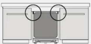
- Before starting the installation, check all the dimensions of the built-in compartment by comparing them with the instructions contained in this manual. Note that it is possible to align the door with the doors of other furniture, even if it exceeds the control panel in height;
- Make sure the installation area is stable and solid;
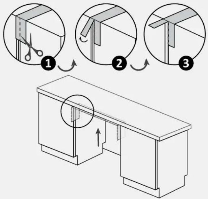
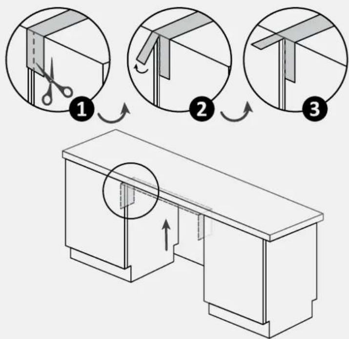
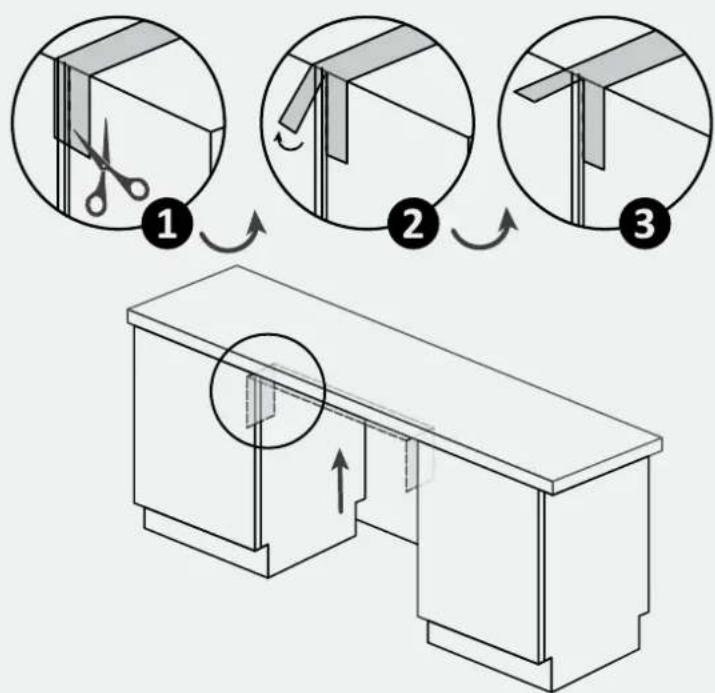
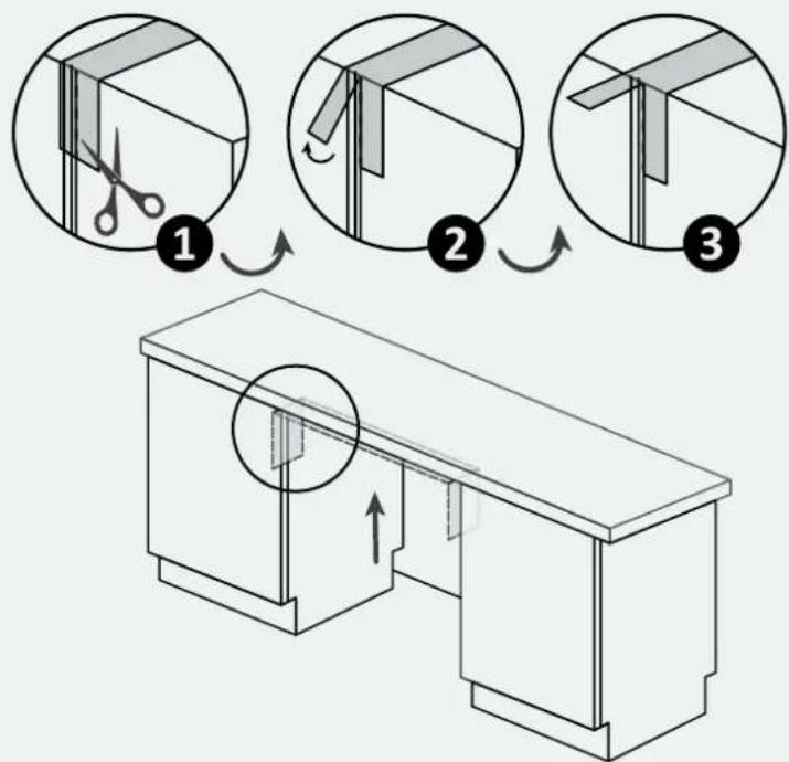
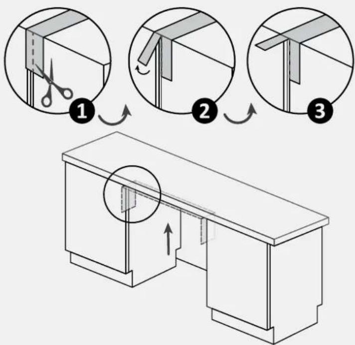
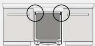
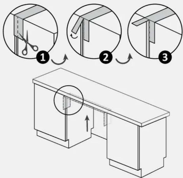
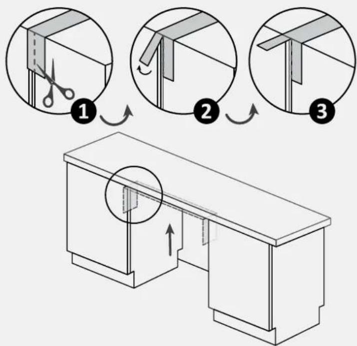
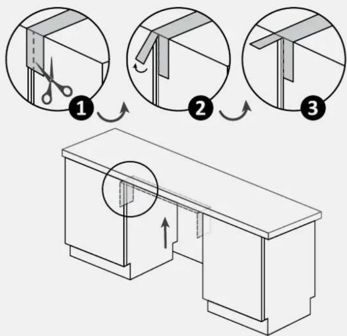
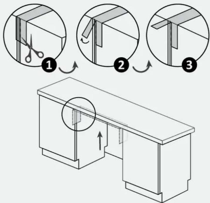
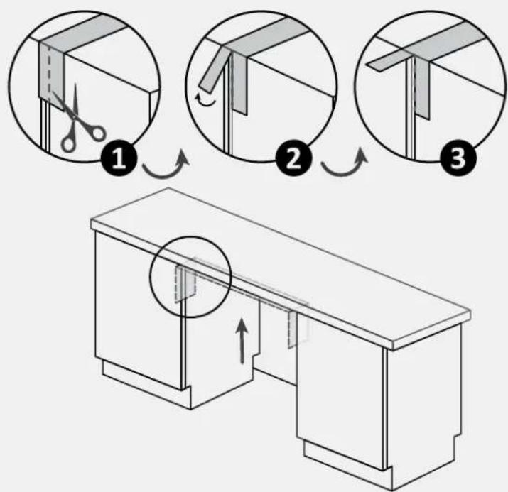
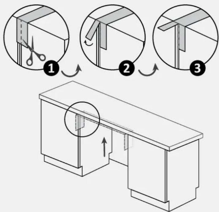
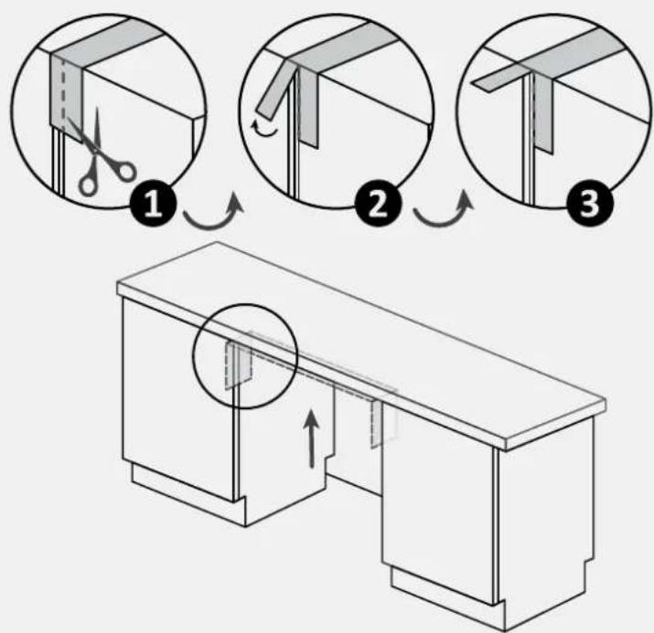
- Apply the protective film, supplied in the installation kit, under the worktop and on surrounding furniture. This film protects the furniture from humidity;
- Be careful when opening and closing the product;
- Incorrect installation can cause the product to tip over;
- The product must be level to function correctly, otherwise the door will not close properly, leading to the escape of hot steam.
Where to install the dishwasher
2
- Install and use this product in a closed, covered, dry, and well-ventilated environment;
- Do not install the product in open environments exposed to atmospheric agents; • Install the product near an electrical outlet;
- Use the product only when placed in a recessed compartment, otherwise you risk injury and burns;
- Do not install the dishwasher under a cooktop;
- Do not install the product near heat sources (radiators, stoves, etc.);
- Do not place the product on carpets or similar surfaces;
- Place the product on a clean, level, and stable surface.
3 Dishwasher dimensions
Dimensions in mm
Front axonometric view of the product
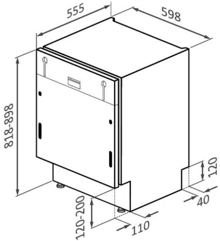
Front axonometric view with kitchen door
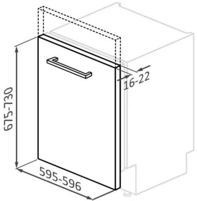

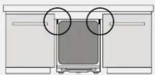
WARNING: if the kitchen panel weighs more than 9 kg contact customer service.
Dimensions in mm
Back view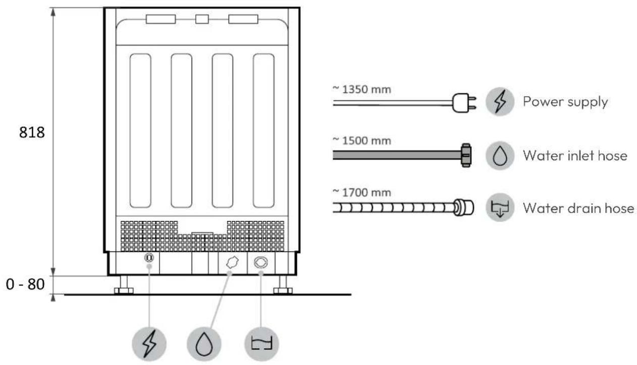
Side view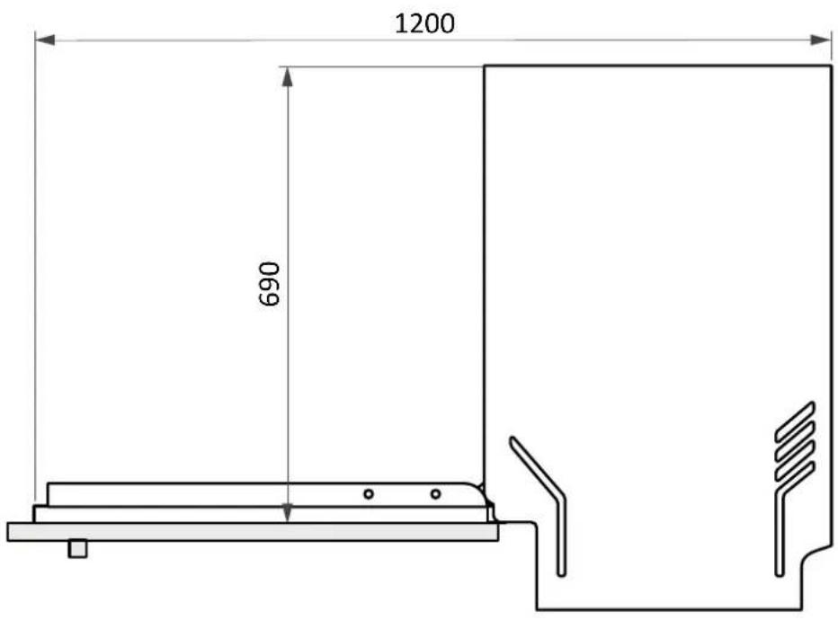
4 Step-by-step installation video
You can watch the product installation video by scanning the QR Code:

or by clicking this

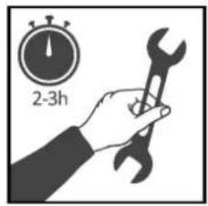
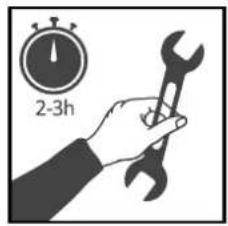
5 Installation tools
Required tools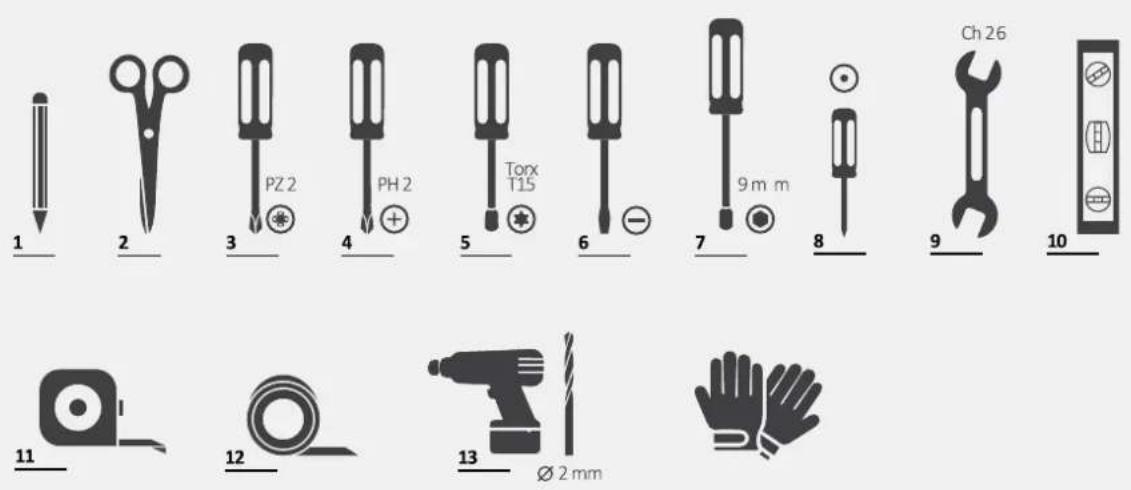
Tools provided with the product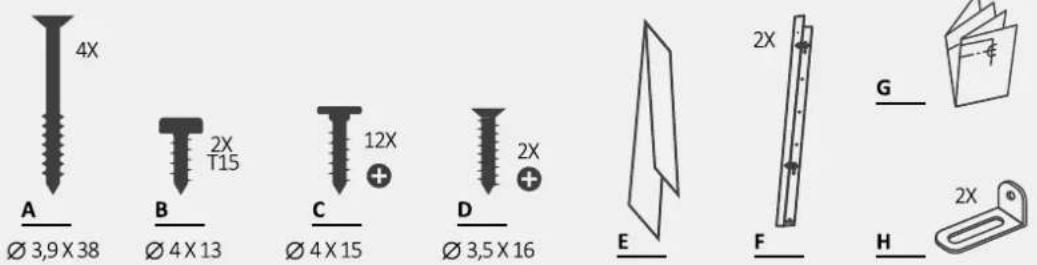
Dimensions in mm
Axonometric view
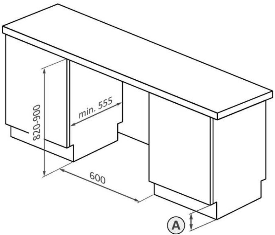
A
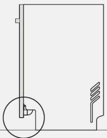
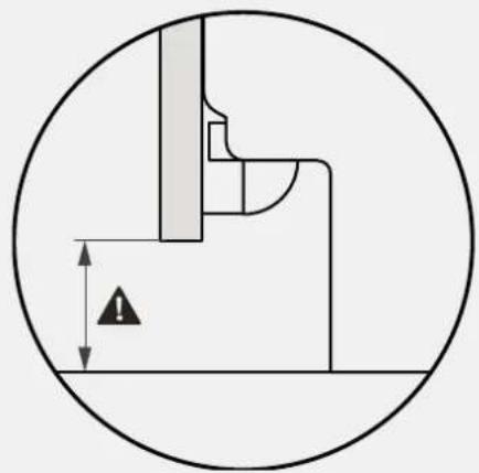
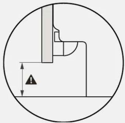
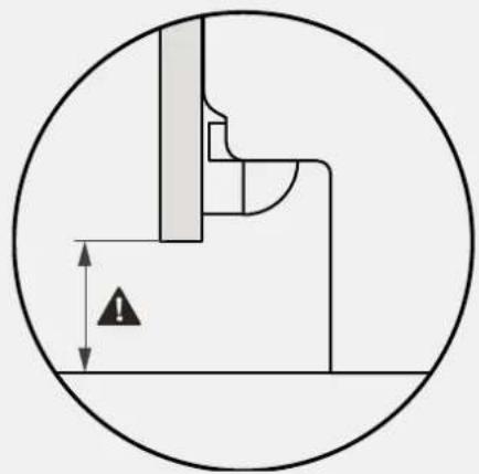
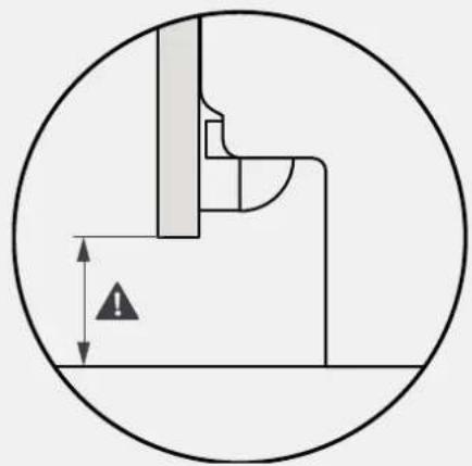
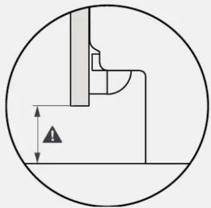
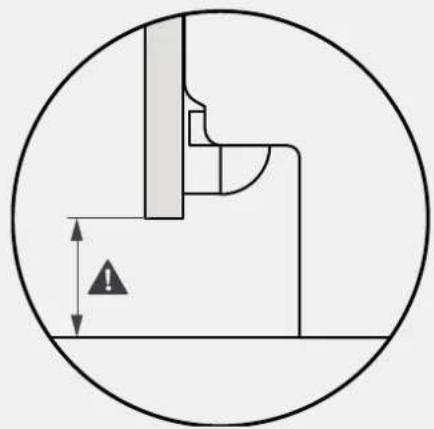
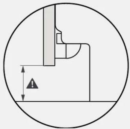
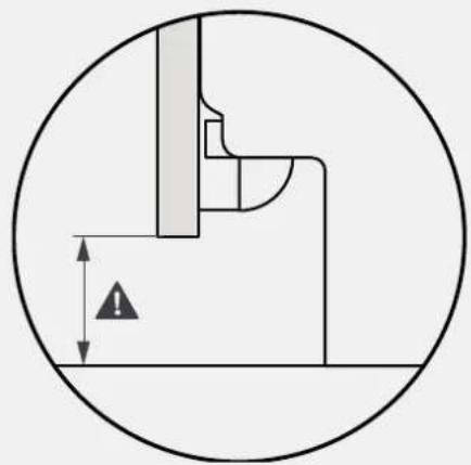
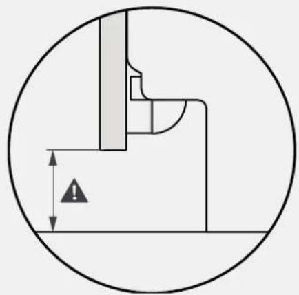
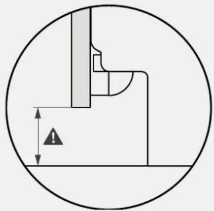
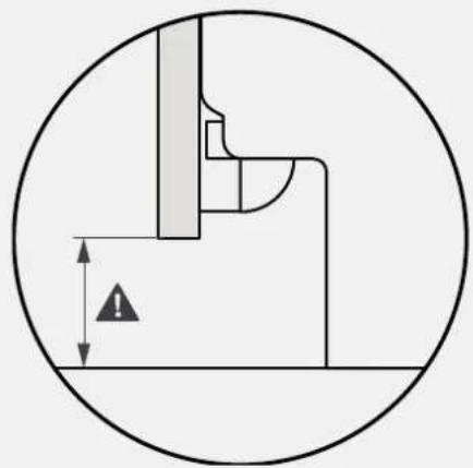
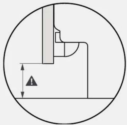
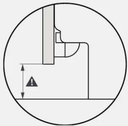
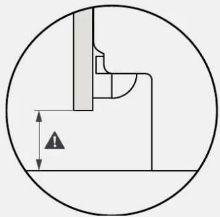
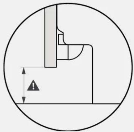
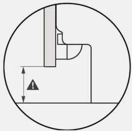
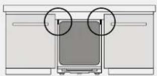
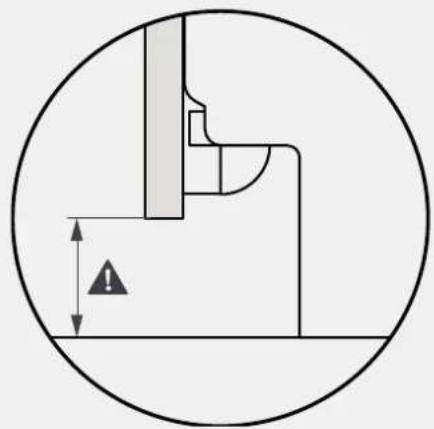
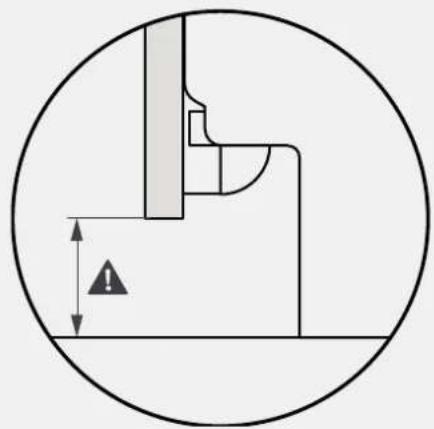
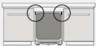
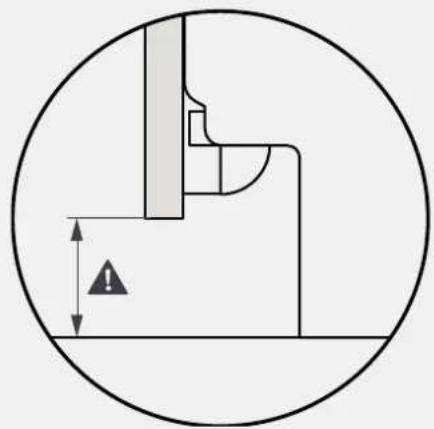
⚠ WARNING: The minimum height of the dishwasher is 818 mm; in this case, the distance between the kitchen door and the floor must be between 90 and 120 mm. If the dishwasher is raised (max. 898 mm), the door-to-floor distance must also increase proportionally, up to a maximum between 170 and 200 mm.
7 Instructions for dishwasher installation
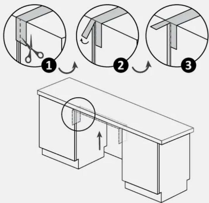
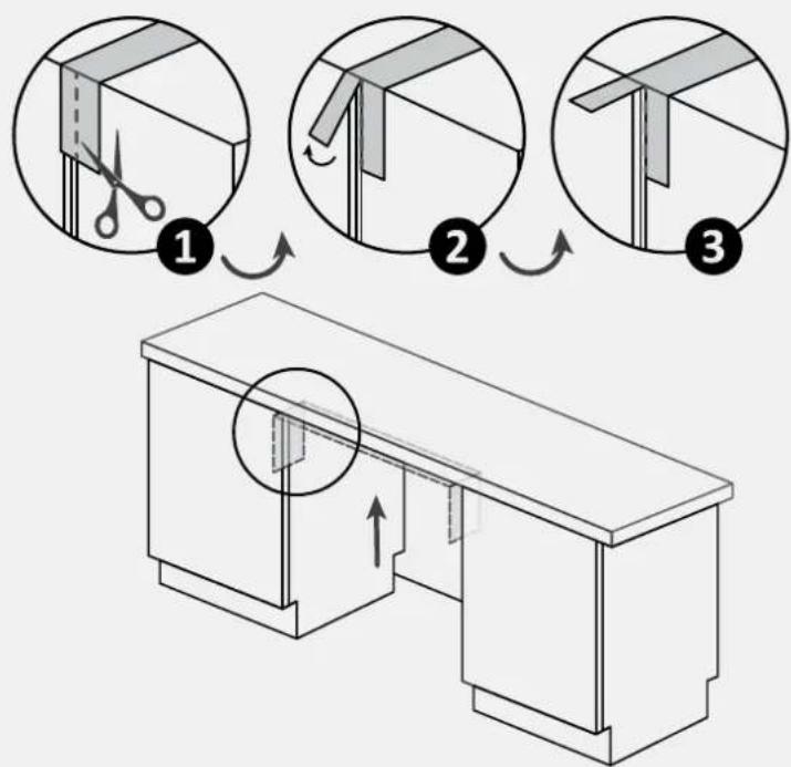
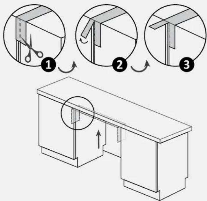
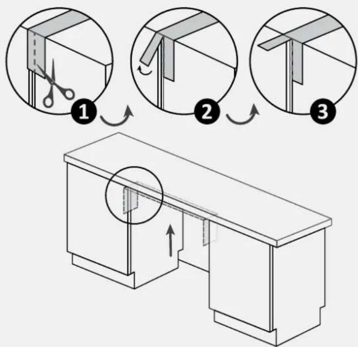
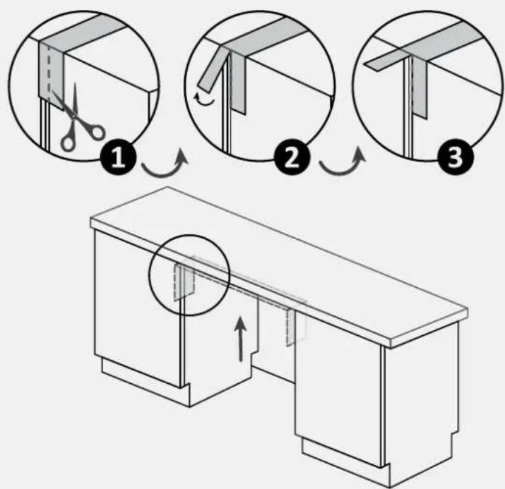
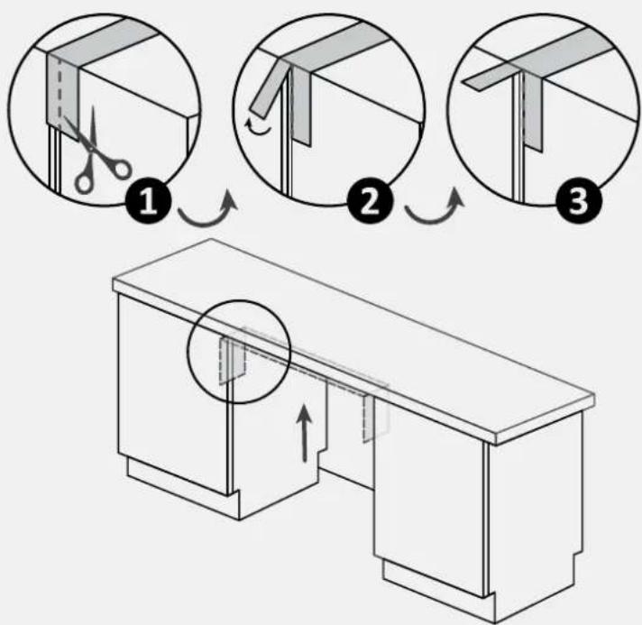
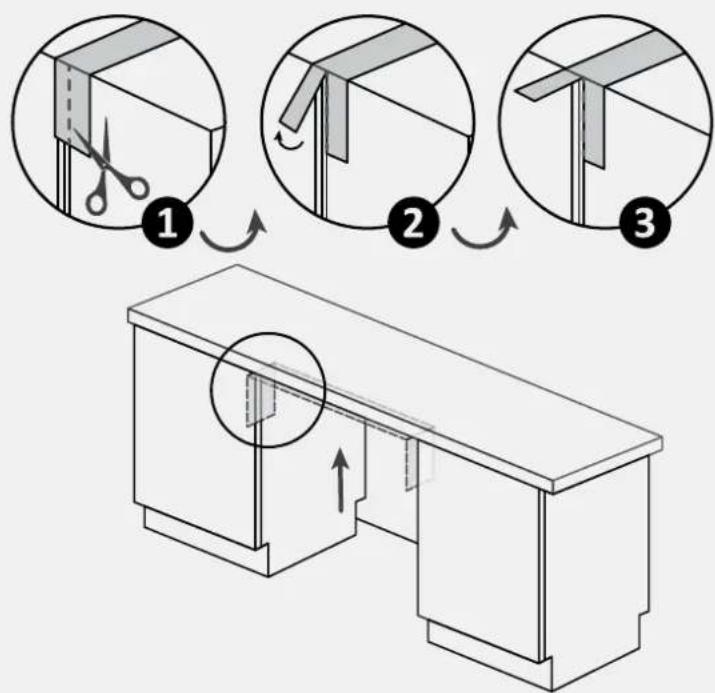
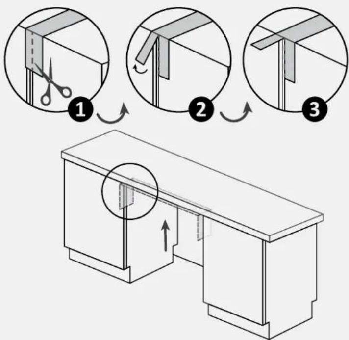
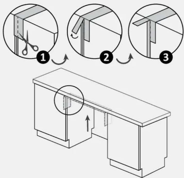
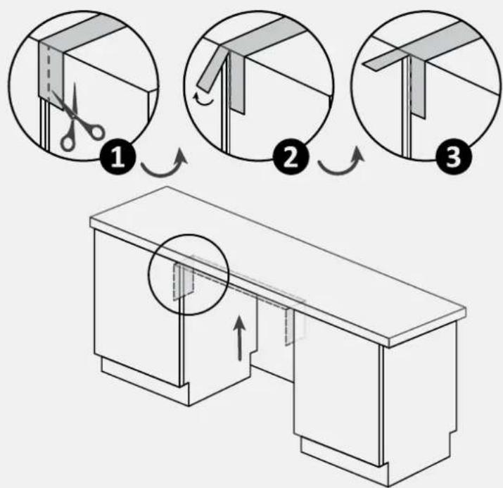
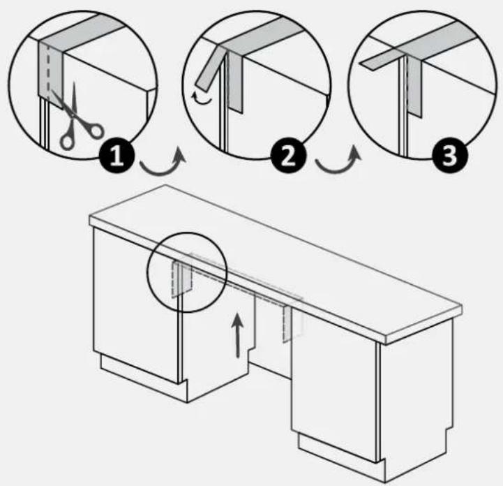
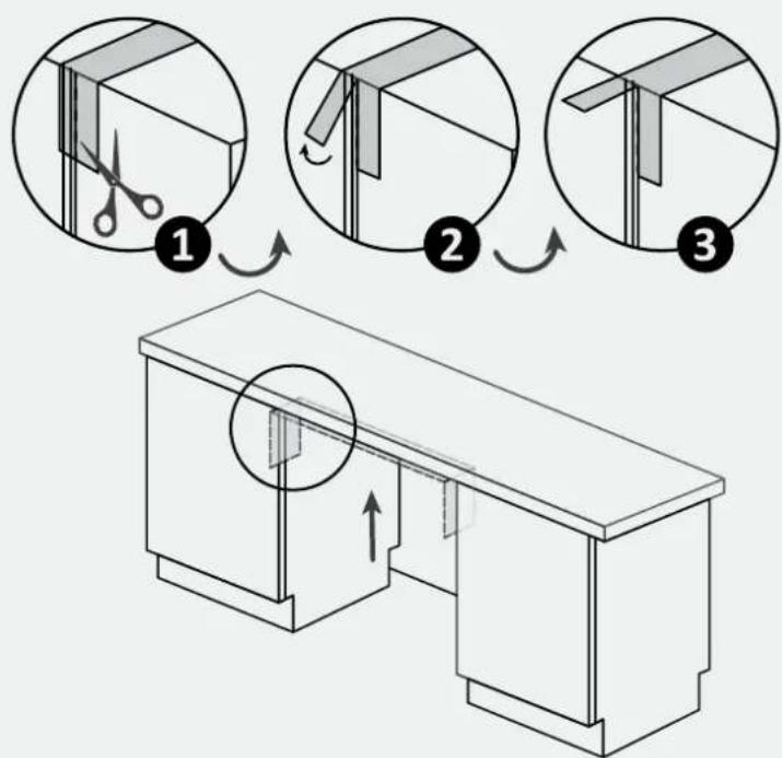
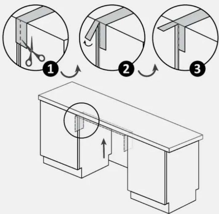
7.1 Steam band installation
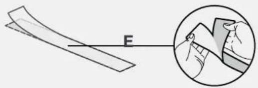
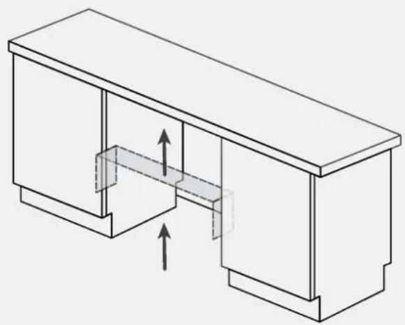
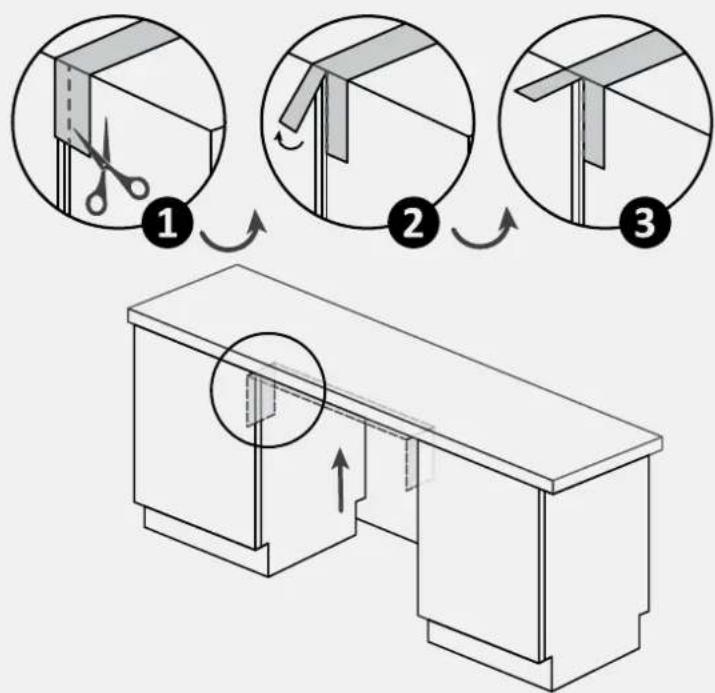
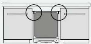
Apply the sticker band under the worktop and to the sides of the adjacent furniture;
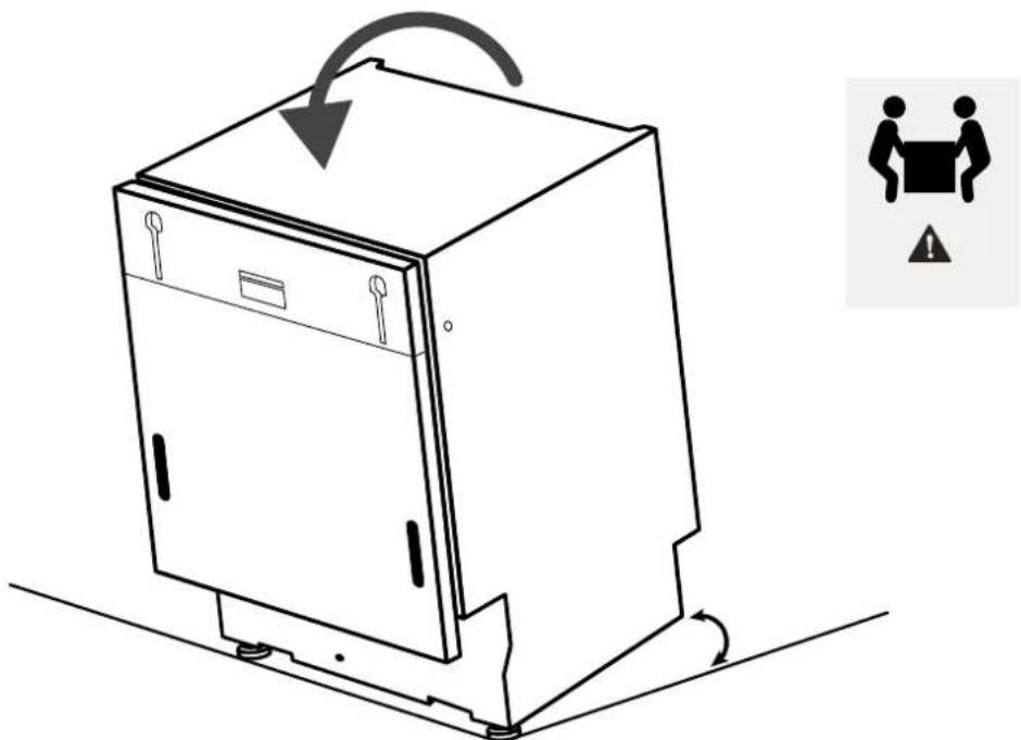
7.2 Height adjustment
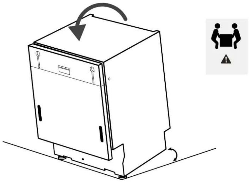
Incline the dishwasher by raising the back about 10 cm.
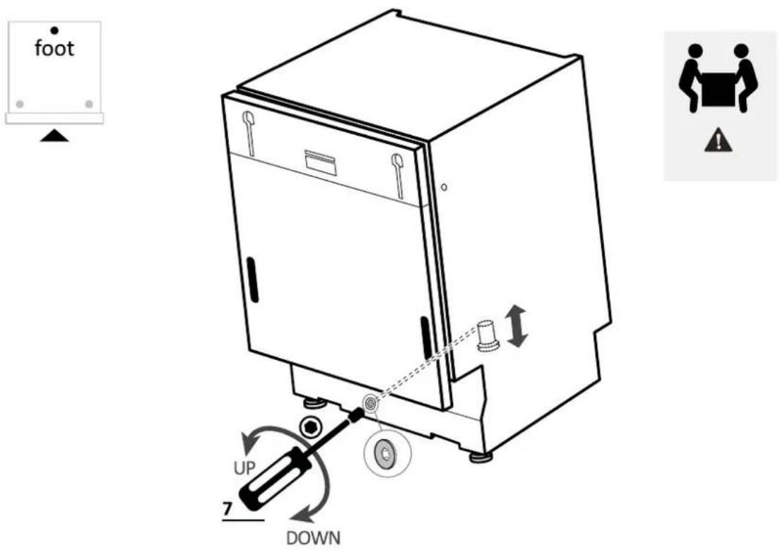
7.3 Rear foot adjustment
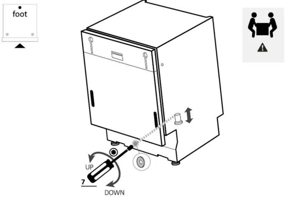
Adjust the rear foot height by operating from the front of the machine as indicated below.
7 Instructions for dishwasher installation
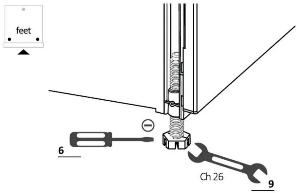
7.4 Front feet adjustment
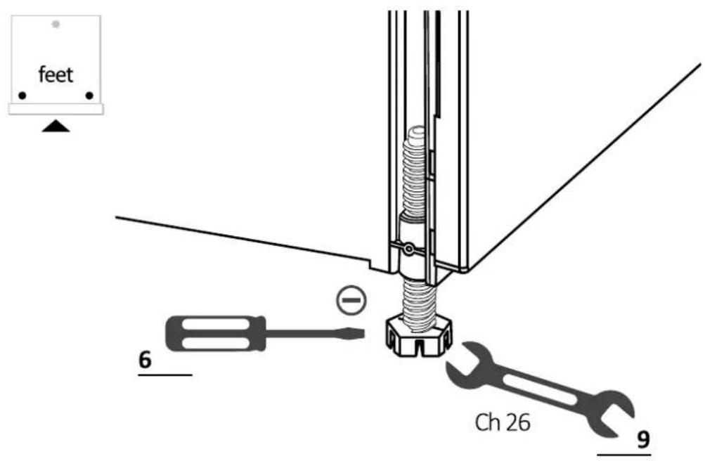
Adjust the front feet directly. If necessary, lift the dishwasher slightly.
7.5 Tilt adjustment
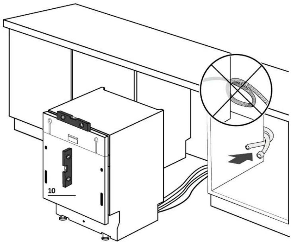
Level the dishwasher by the vertical and horizontal planes.
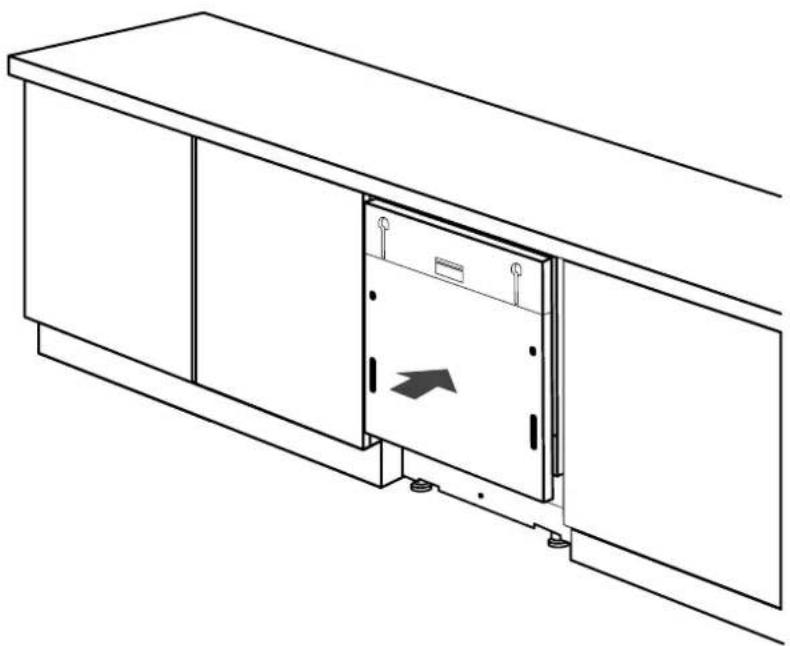
7.6 Insertion into the built-in compartment
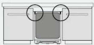
Insert the dishwasher into the built-in compartment and check measurements and tolerances.
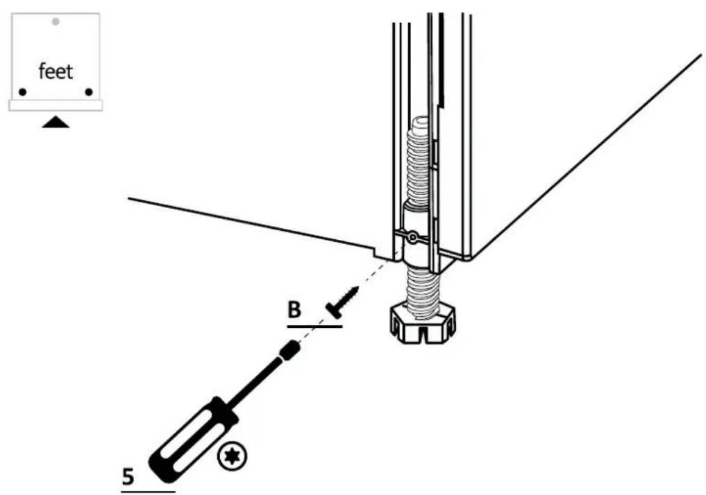
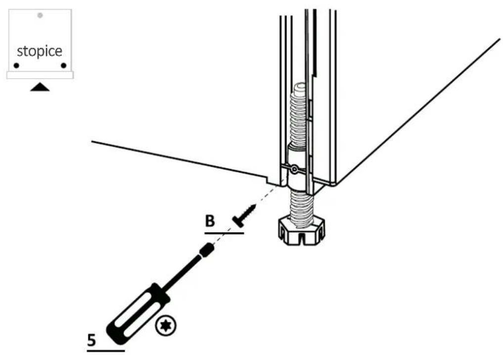
7.7 Fixing the front feet
After checking all measurements, permanently fix the front feet to prevent them from loosening over time. This operation can also be done after installing the kitchen panel.
7 Instructions for dishwasher installation
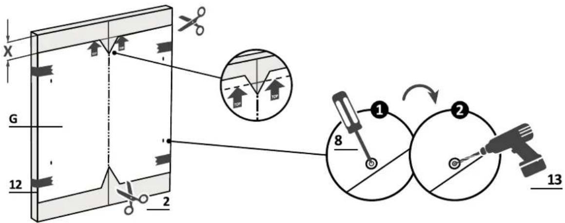
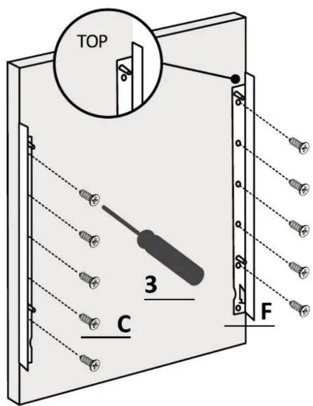
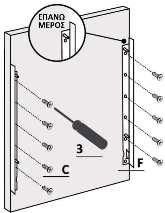
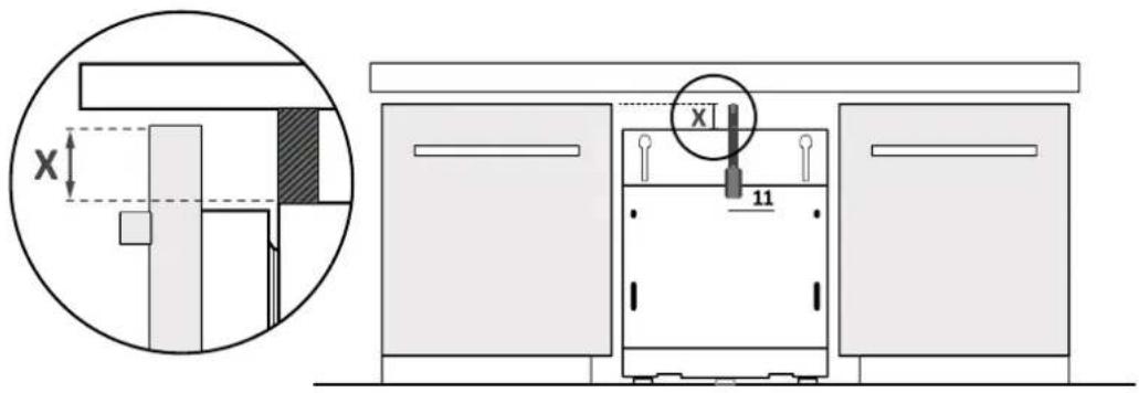
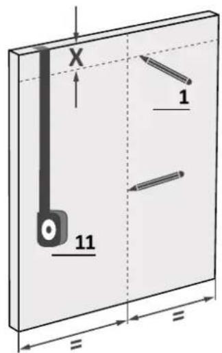
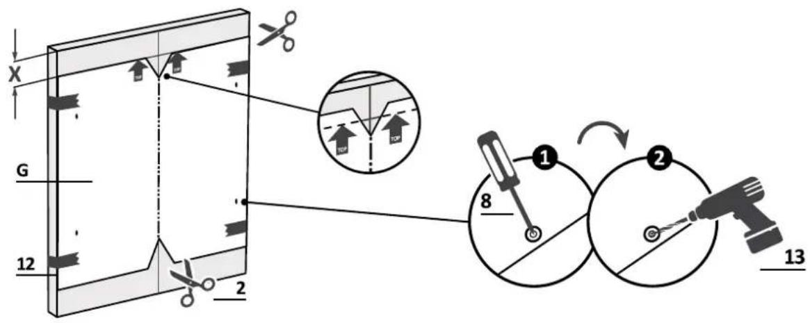
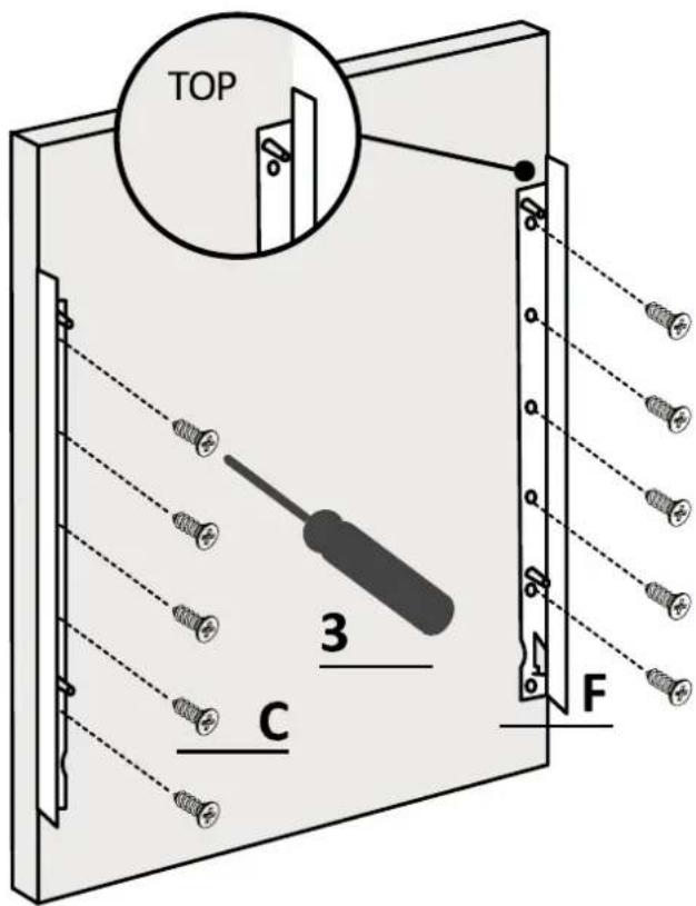
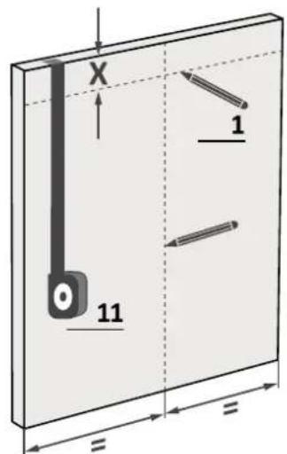
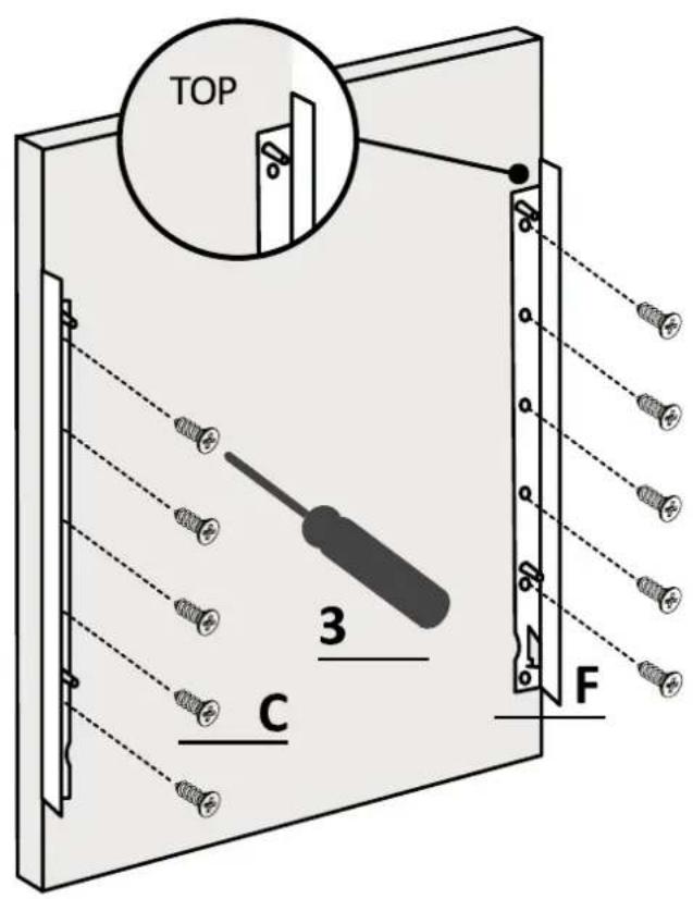
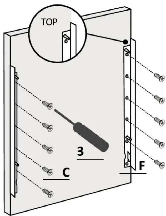
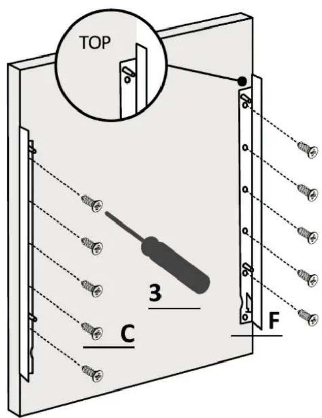
7.8 Panel preparation
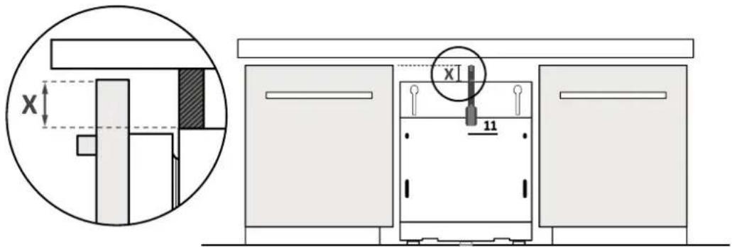
1.
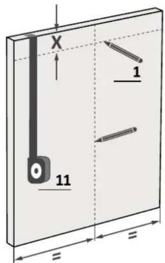
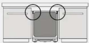
Measure the distance between the top edge of the adjacent doors and the dishwasher;
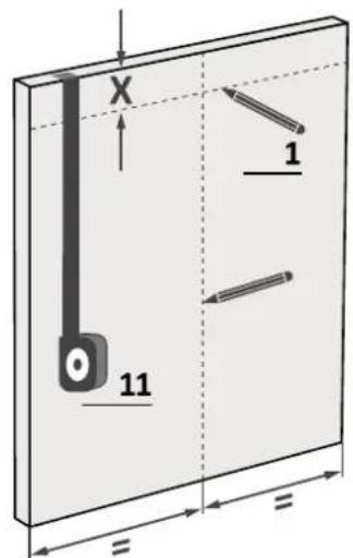
2.
Transfer the measurement onto the kitchen panel and locate the center;
3.
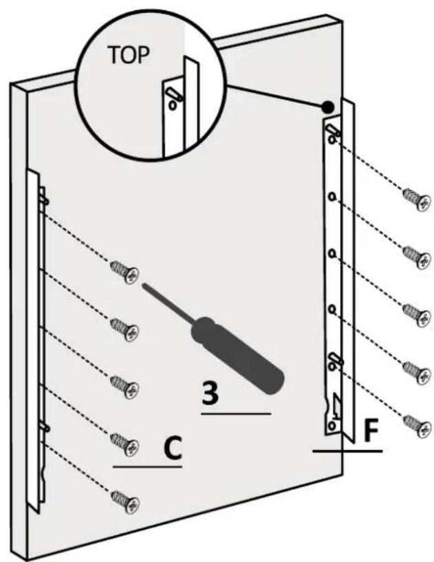
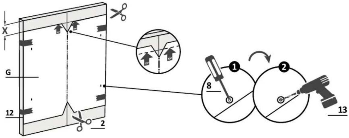
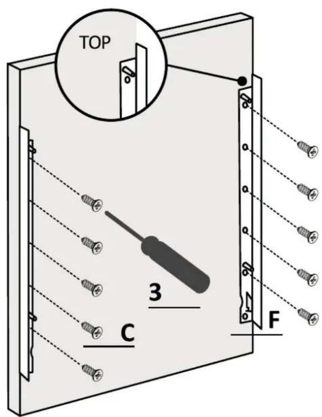
Apply the drilling template and follow the instructions provided.
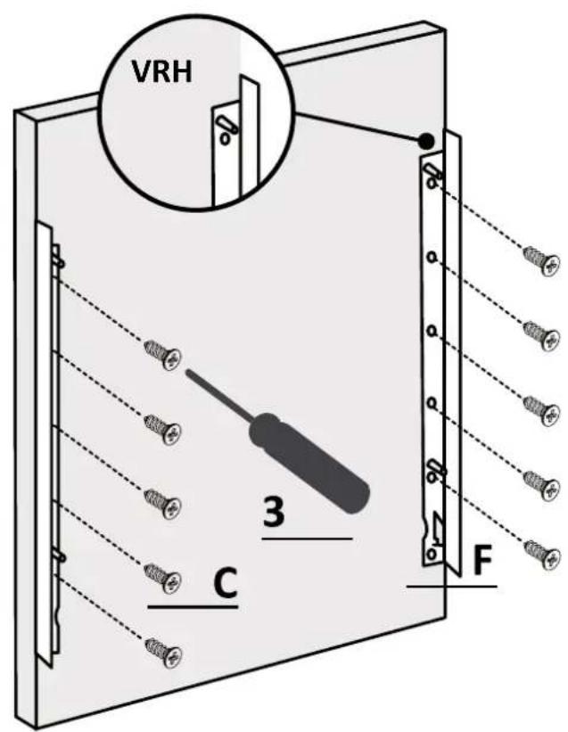
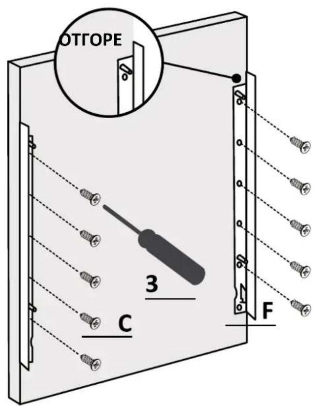
7.8 Panel preparation
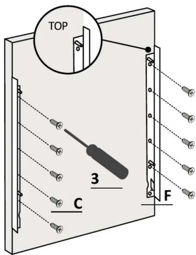
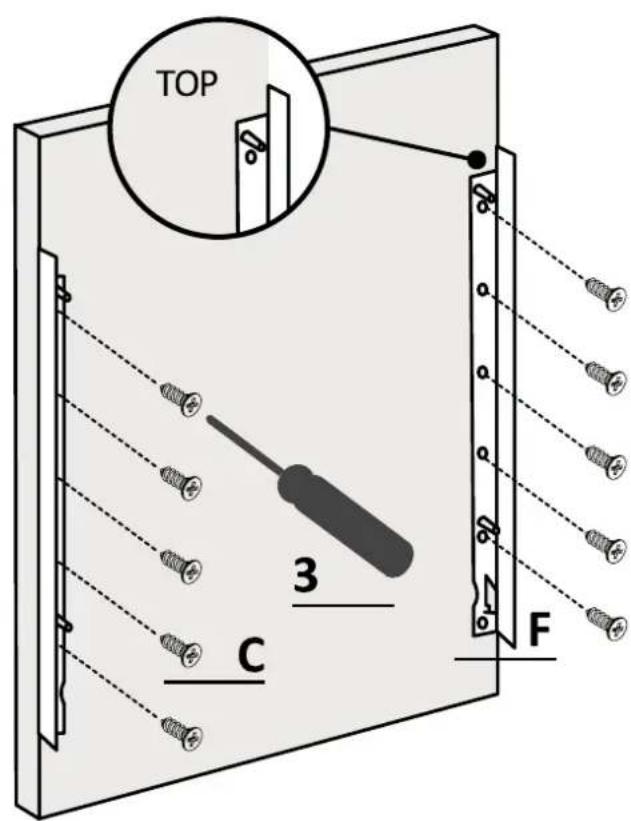
4.
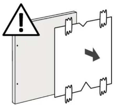
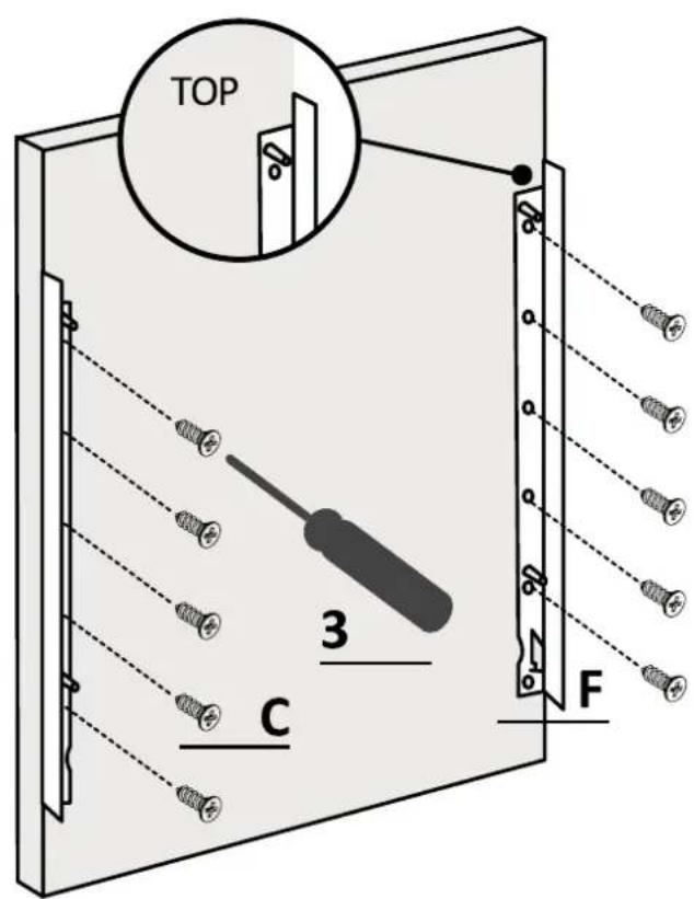
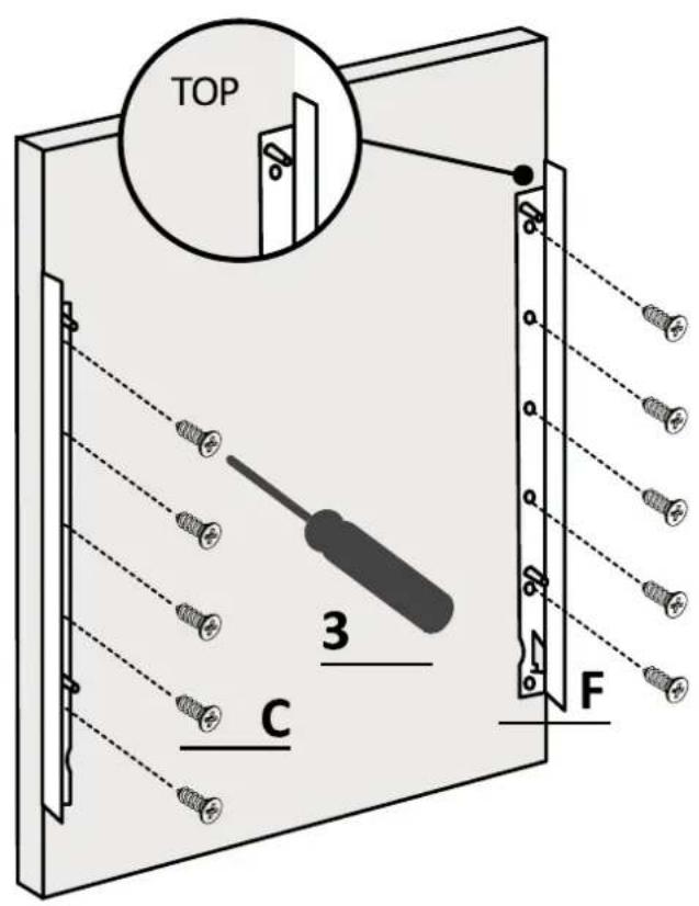
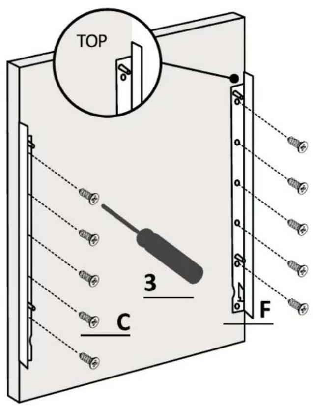
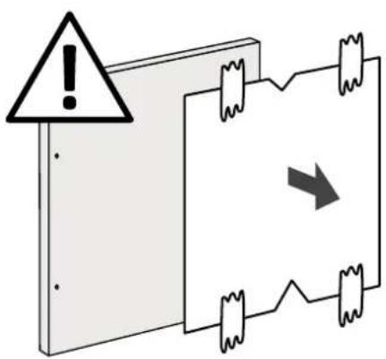
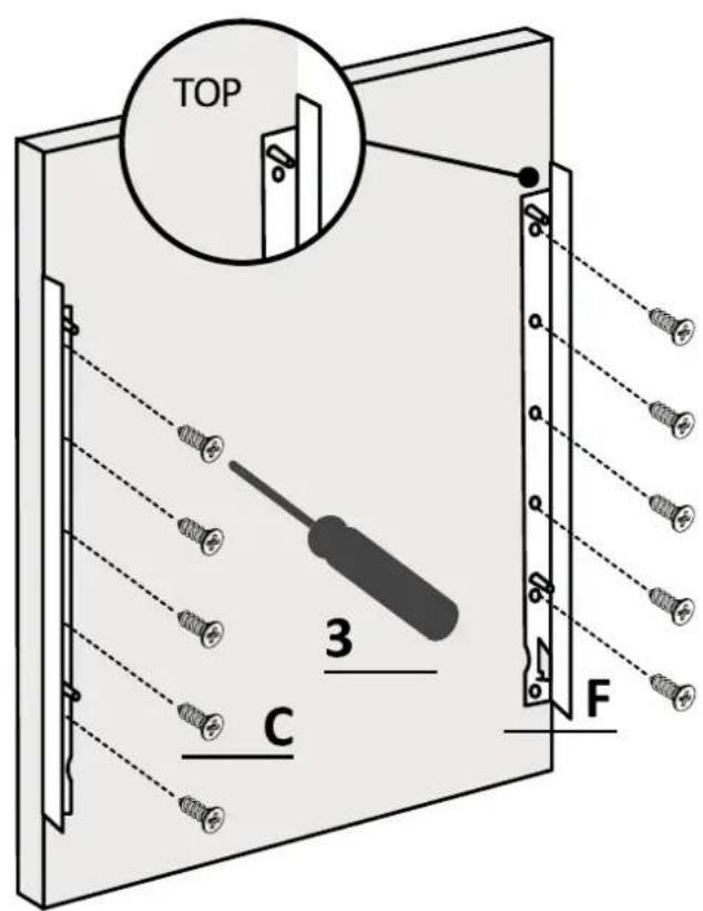
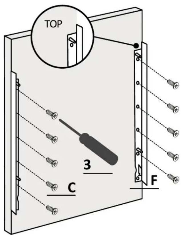
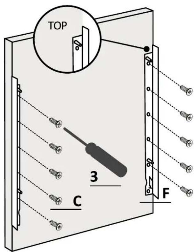
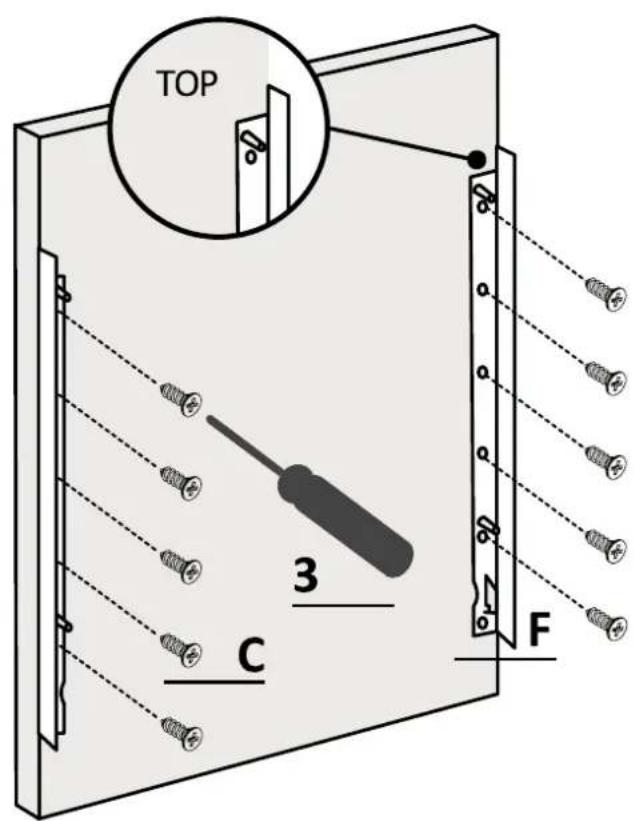
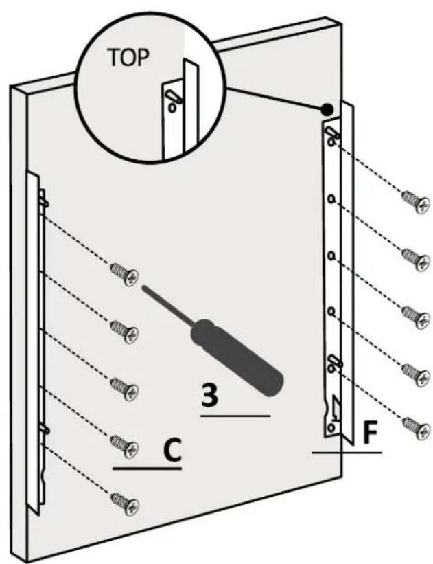
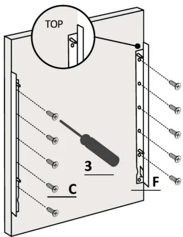
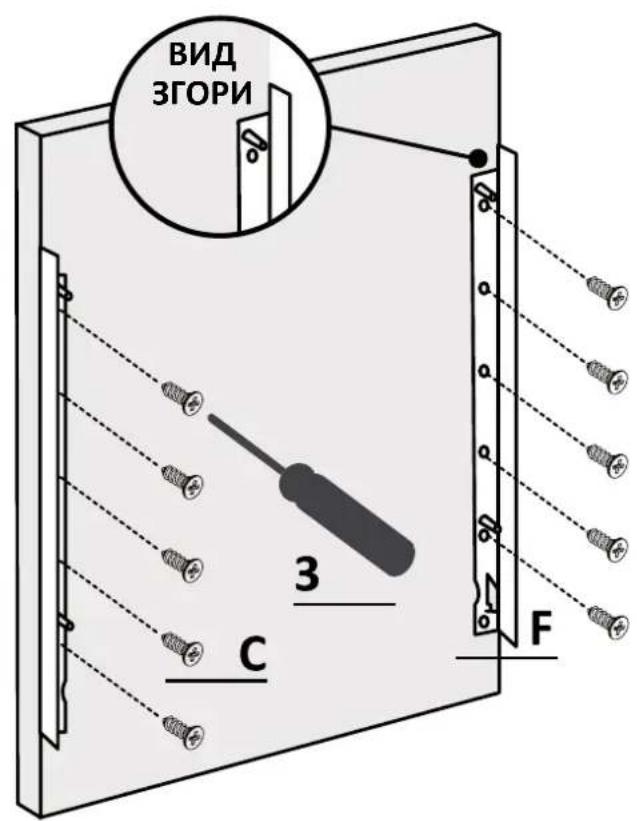
Remove the drilling template and apply the accessories.

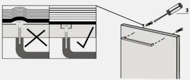
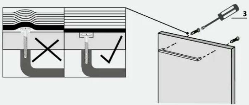
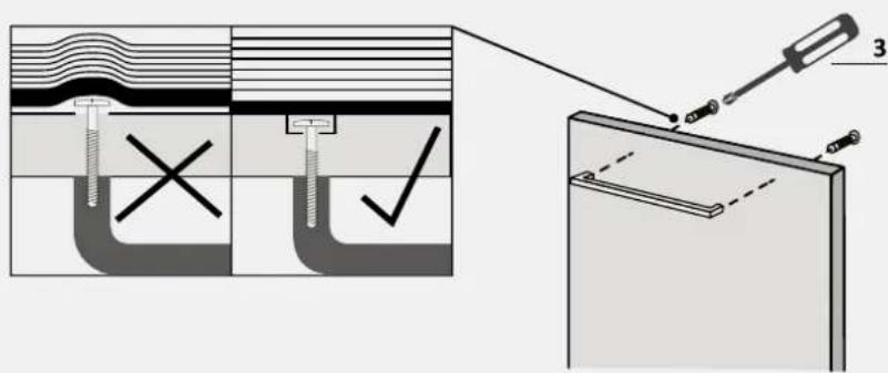
⚠ WARNING: Ensure screw heads don't protrude from the panel's rear surface, especially if you install the handle.
7 Instructions for dishwasher installation
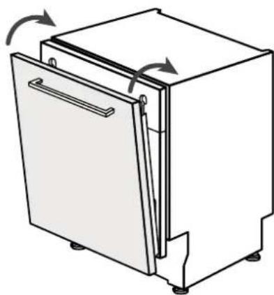
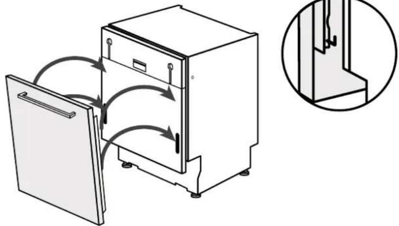
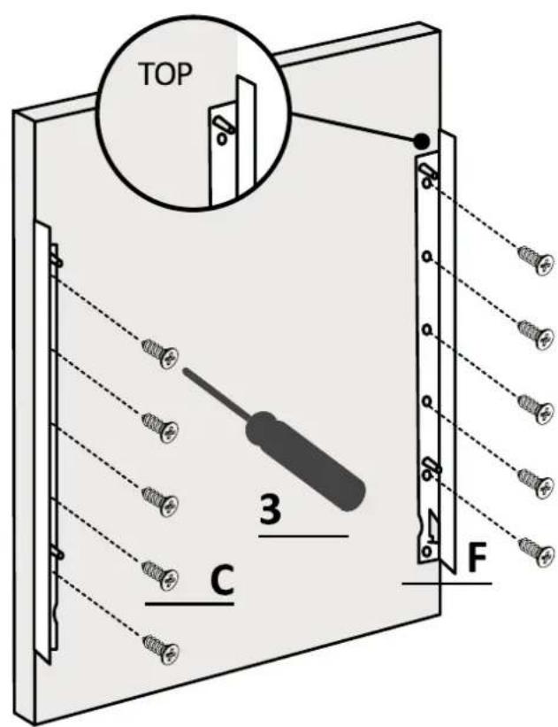
Installation of the panel 7.9
1.
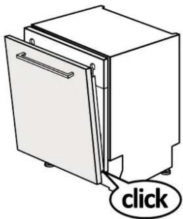
Attach the panel to the dishwasher;

2.
Fix the panel to the lower part of the dishwasher;
3.
Fix the panel to the upper part of the dishwasher;
7.9 Installation of the panel
4.
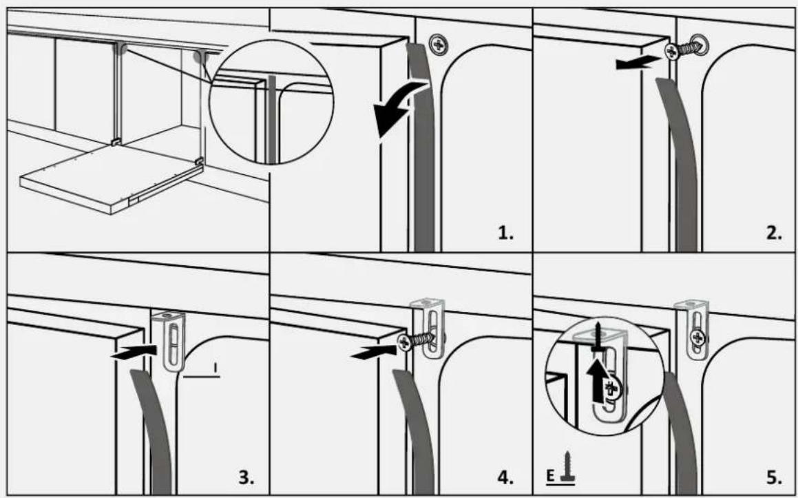
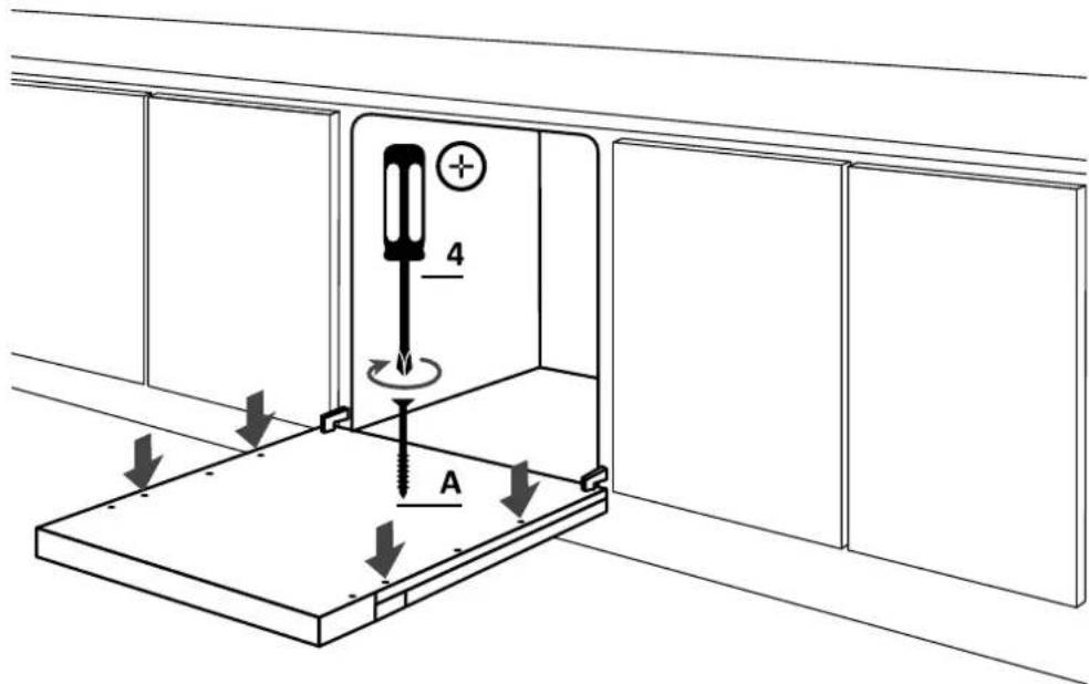
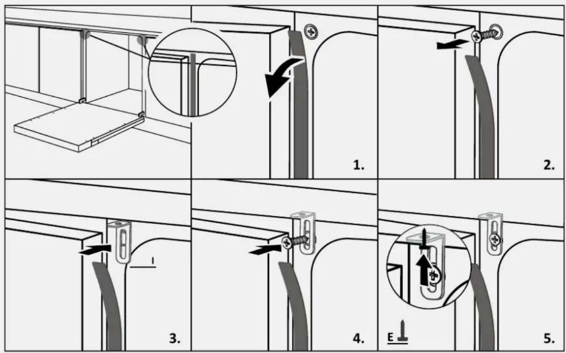
Open the dishwasher door while holding the lower part of the kitchen panel, then unscrew the lower screws;
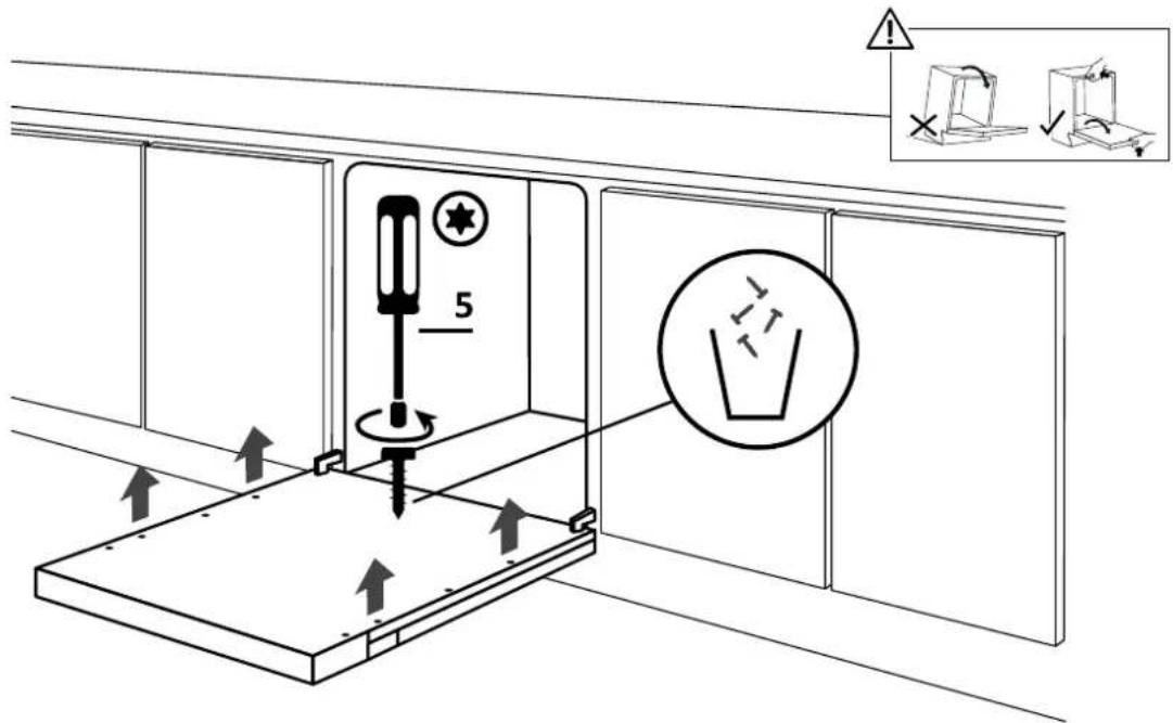
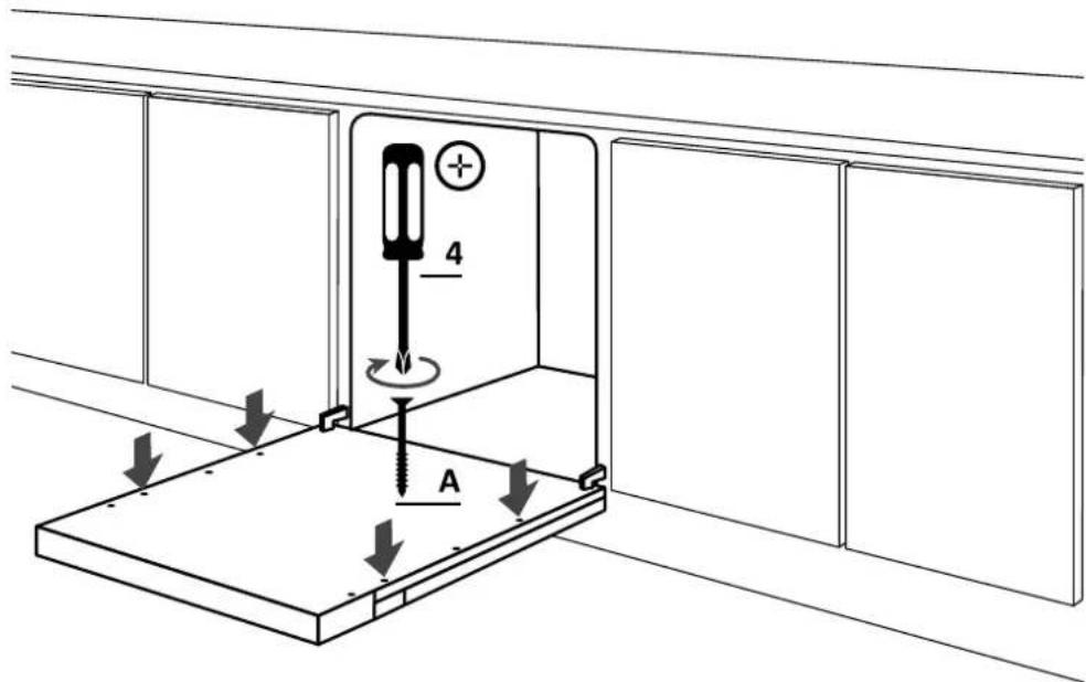
5.
Make sure the panel is fully inserted; fix the kitchen panel to the dishwasher using the supplied screws.
7 Instructions for dishwasher installation
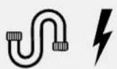
⚠ WARNING: Connect the dishwasher now to the water and electrical network, following the instructions in chapter 8.
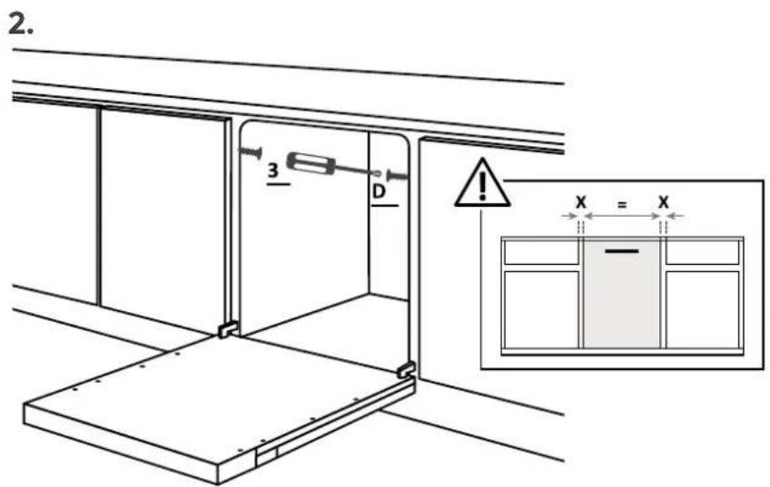
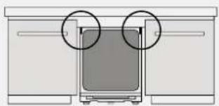
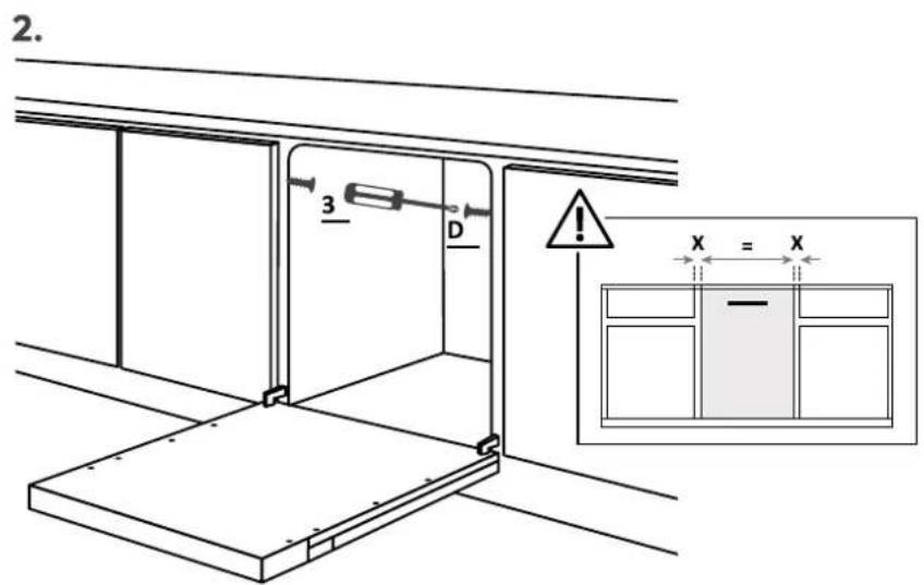
7.10 Fixing the machine to the kitchen
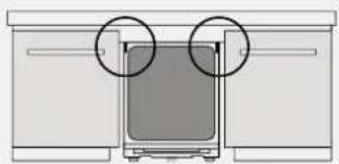
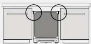
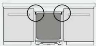
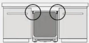
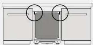
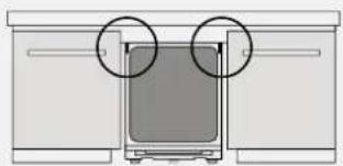
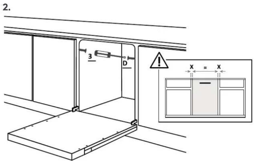
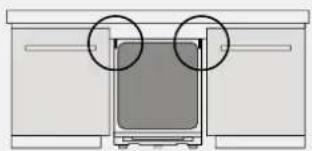
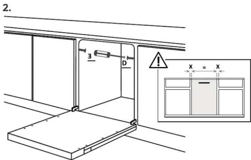
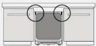
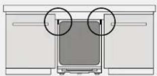
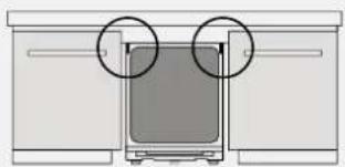
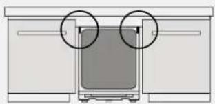
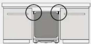
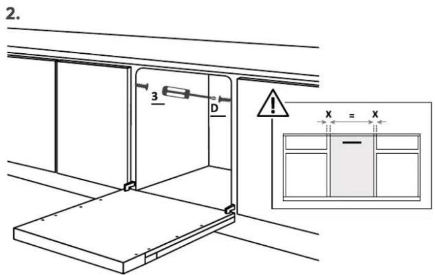
Instructions for fixing the dishwasher laterally to the adjacent cabinets.
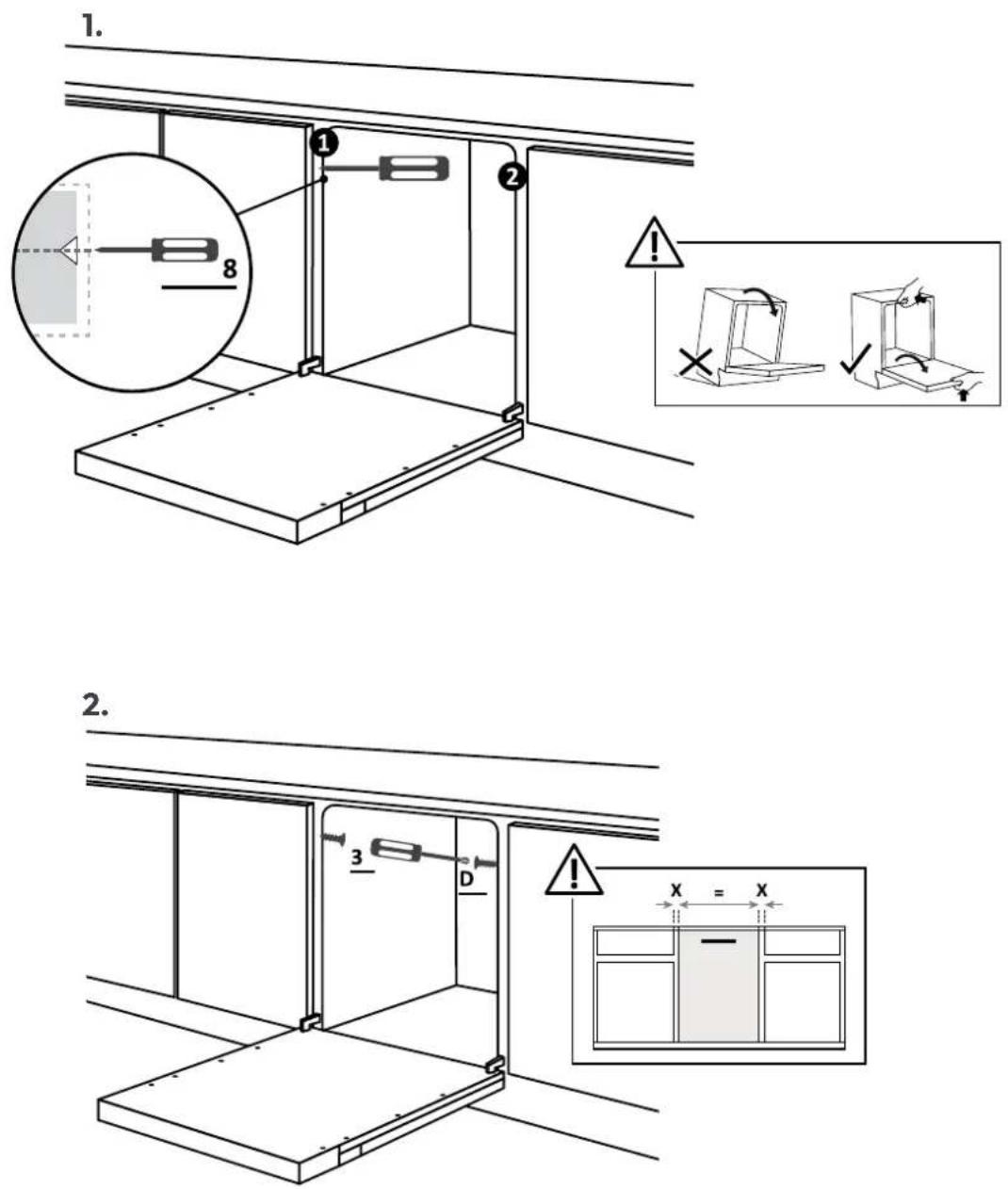
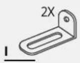
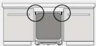
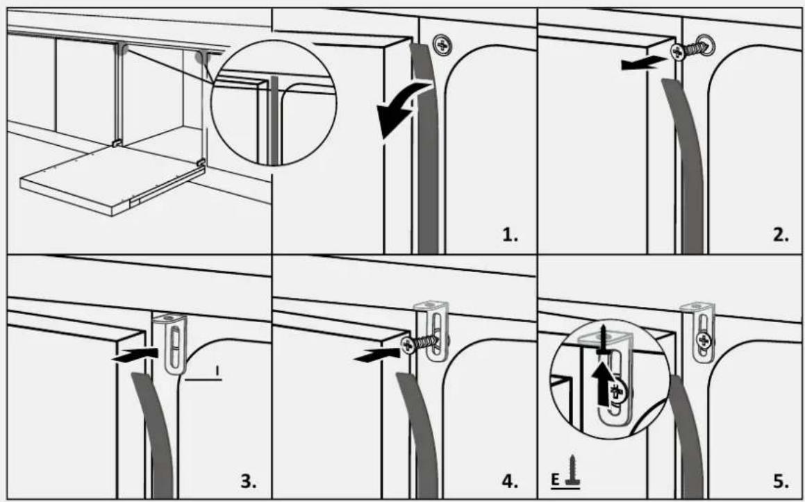
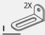
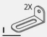
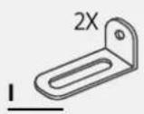
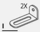
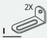
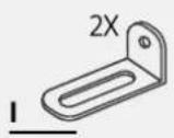
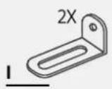
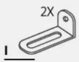
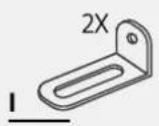
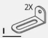
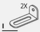
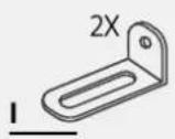
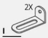
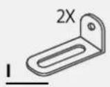
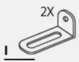
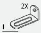
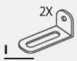
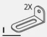
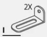
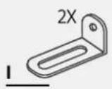
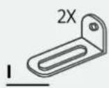
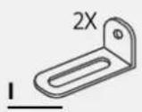
⚠ WARNING: If it is not possible to fix the dishwasher laterally, use the supplied brackets and fix it to the worktop; pay attention if the latter is not made of wood.
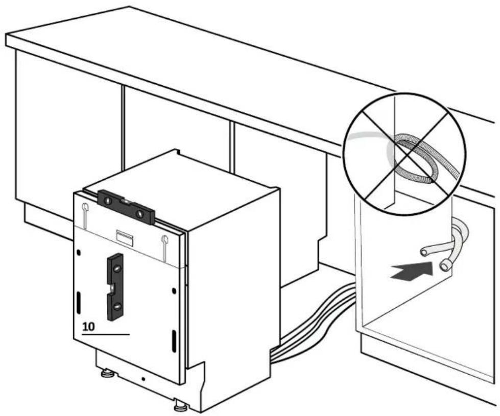
8 Drain water and electricity connection
8.1 Connection diagram
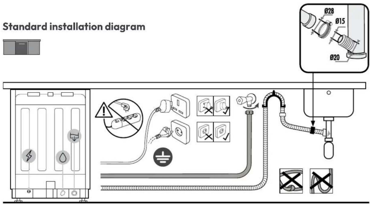
Column installation diagram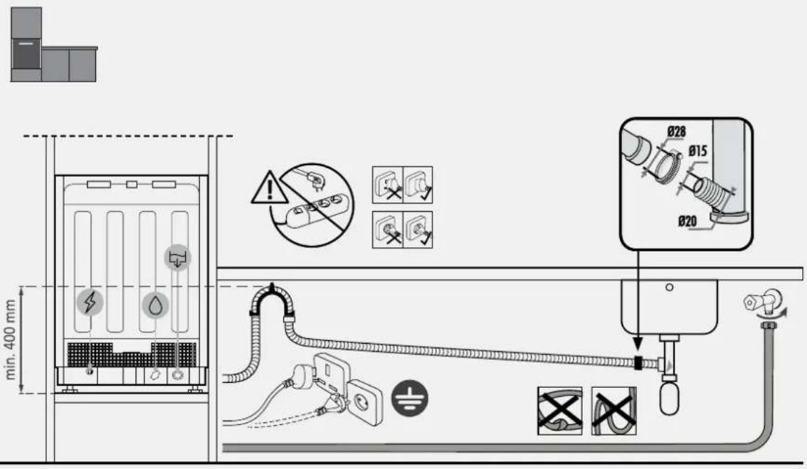

WARNING: Ensure that the water pressure is between 0.08 MPa and 1 MPa.
8.2 Safety devices
All dishwashers are equipped with an anti-overflow safety device which, in the event that the water exceeds the normal level due to a malfunction, automatically blocks the water flow and/or drains the excess water.
See the User Manual for more details.
Delivery to the user
9
At the end of installation:
- Inform the user about essential functions;
- Inform the user about all aspects relevant to safe use and handling;
- Deliver accessories and instructions for use and assembly to the user to be kept with care.
After installation is complete, remove the protective film, tape, and all other packing materials and remove the supplied accessories from inside the product.

NOTE: The actual appearance of the product depends on the model chosen.
Dishwasher disassembly
10
- Disconnect the product from the electrical and water supply;
- Unscrew the fastening screws;
- Slightly lift the product and pull it out completely;
- This product does not damage the furniture, which can also be used with a new appliance.
5 Installation tools
Outils nécessaires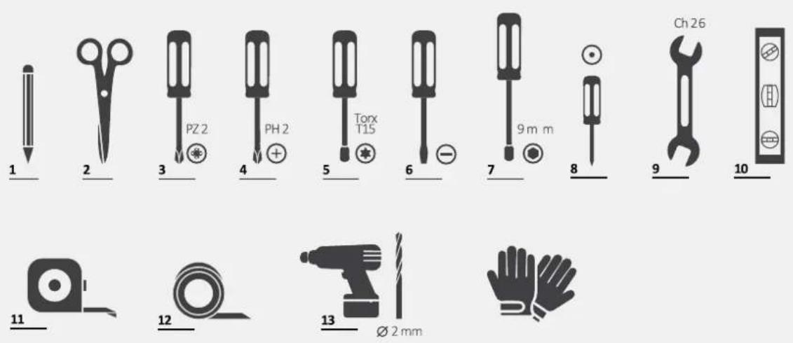

2.
7.9 Plate installation
4.
WELCOME
3.
7.3 Adjusting the rear foot
2.
2.
WELCOME
2.
2.

WELCOME
7.2 Height adjustment
7.5 Tilt adjustment
Level the dishwasher with respect to the vertical and horizontal plane.
2.
2.
5.
WELCOME
This installation instruction is intended for kitchen manufacturers who will install these products. To ensure safety and achieve the best results, carefully read this instruction, including the safety instructions, and keep it for future reference. Before proceeding with installation, record the serial number, as it may be needed in case of repairs. Check for transport damage and consult a technician if in doubt before use. Always keep all packaging materials out of reach of children.
NOTE: The functions and images contained in this document are for reference only and may change without prior notice.
Index
1 Safety notices for installation p. 2-3 2 Where to install the dishwasher p. 3 3 Dishwasher dimensions p. 4-5 4 Video for detailed installation p. 6 5 Installation tools p. 6 6 Installation dimensions p. 7 7 Dishwasher installation instructions p. 8–17 7.1 Mounting the anti-condensation strip 7.2 Adjusting the height 7.3 Adjusting the rear foot 7.4 Adjusting the height of the front feet 7.5 Adjusting the tilt 7.6 Inserting into the built-in kitchen element 7.7 Securing the front feet 7.8 Preparing the door panel 7.9 Installing the door panel 7.10 Securing the dishwasher to the kitchen 8 Connection to water and electrical supply p. 18–19 8.1 Connection diagram 8.2 Safety devices 9 Handover to the user p. 19 10 Removing the dishwasher p. 19
or by clicking on this
5 Installation tools
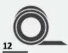
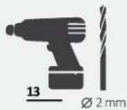
Required tools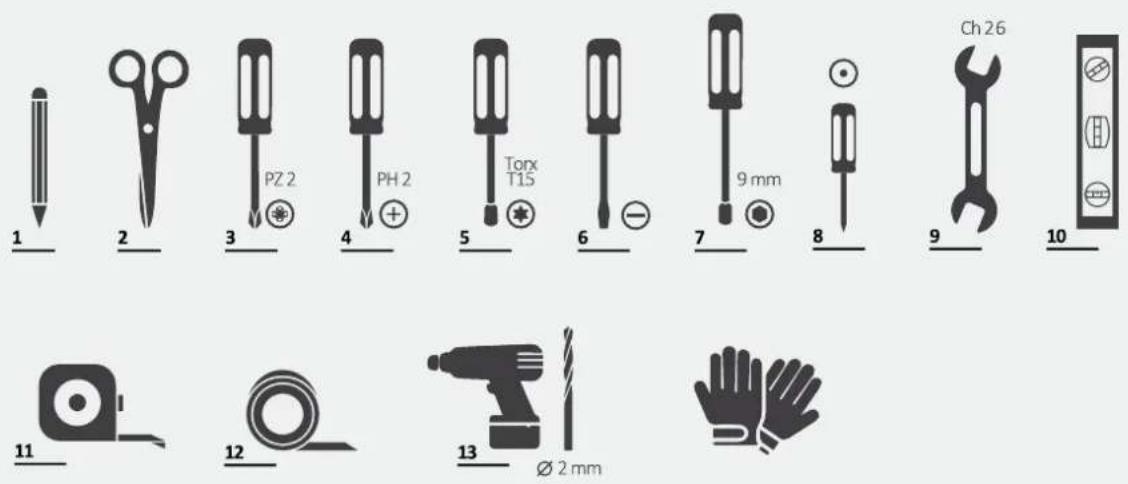


⚠ WARNING: The minimum height of the dishwasher is 818 mm; in that case, the distance between the kitchen door and the floor must be between 90 and 120 mm. If the dishwasher is raised (max. 898 mm), the distance from the door to the floor must also increase proportionally, up to a maximum of 170 and 200 mm.
7 Dishwasher installation instructions
7.1 Installing the anti-condensation strip
7.7 Securing the front feet
After checking all measurements, permanently secure the front feet to prevent them from loosening over time. This can also be done after installing the kitchen countertop.
7 Installation instructions for the dishwasher
7.8 Preparing the countertop
1.
Measure the distance between the top edge of adjacent doors and the dishwasher;
2.
Transfer the measurement to the kitchen countertop and locate the center;
3.
Apply the drilling template and follow the provided instructions.
7.8 Preparing the countertop
4.
⚠ WARNING: Make sure that the screw heads do not protrude from the back of the countertop, especially if you are installing a handle.
7 Installation instructions for the dishwasher
7.9 Installing the countertop
1.
Attach the panel to the dishwasher;
2.
Attach the panel to the lower part of the dishwasher;
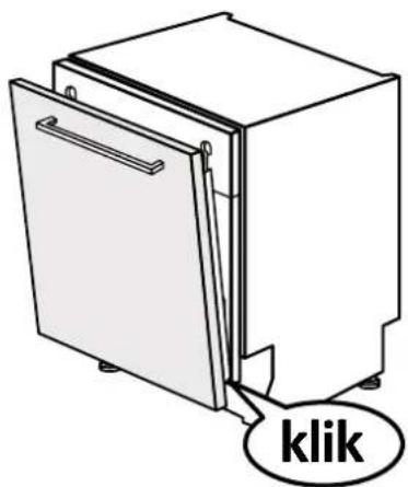
3.
Attach the panel to the upper part of the dishwasher;
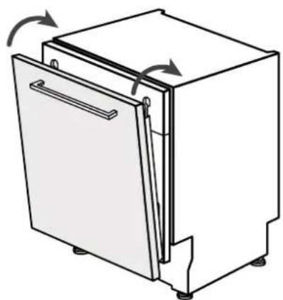
7.9 Panel installation
4.
Open the dishwasher door while holding the lower part of the kitchen panel, then unscrew the lower screws;
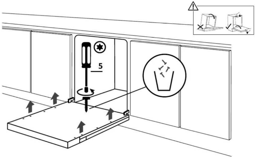
5.
Check that the panel is fully inserted; attach the kitchen panel to the dishwasher using the provided screws.
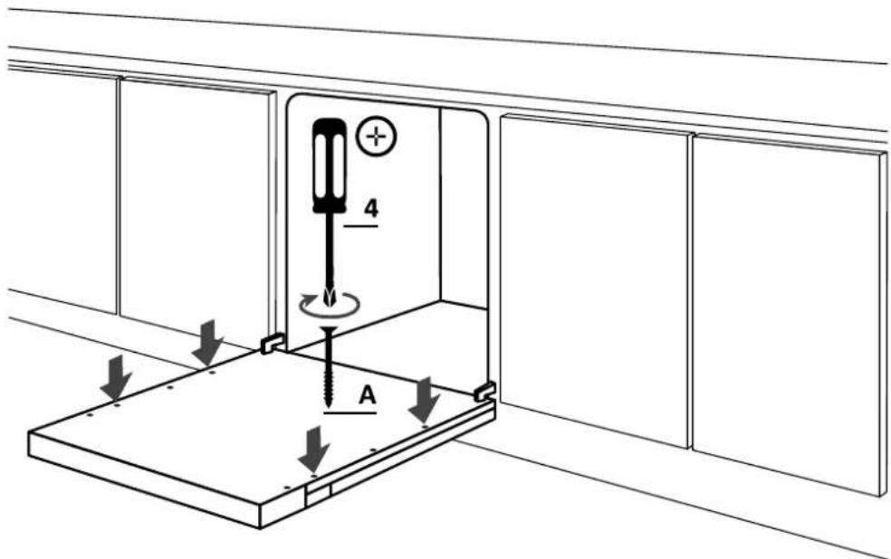
7 Installation instructions for the dishwasher
⚠ WARNING: Now connect the dishwasher to the water and electrical supply, in accordance with the instructions in chapter 8.
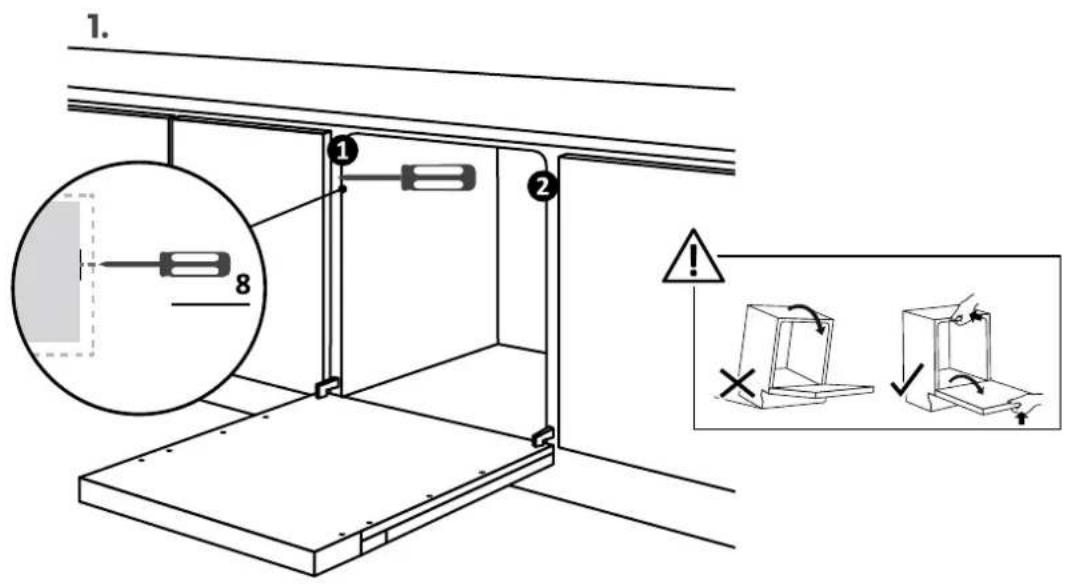
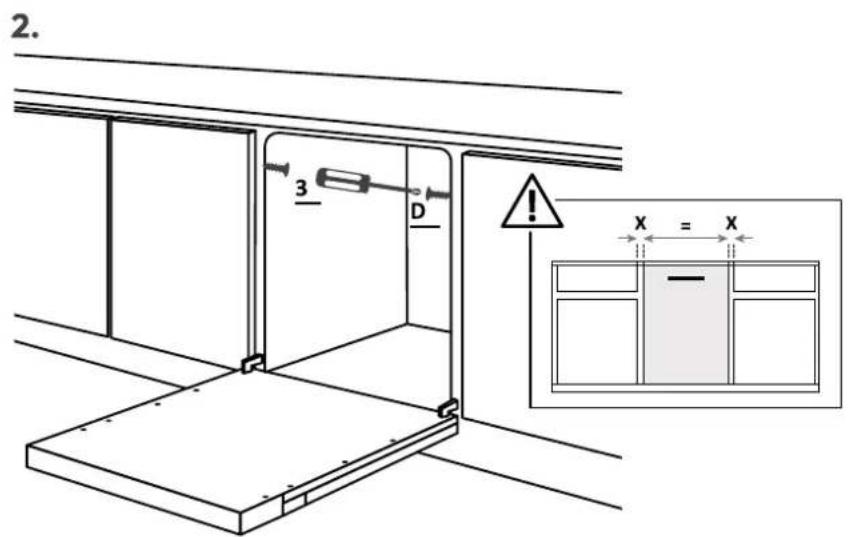
7.10 Securing the dishwasher to the kitchen
Instructions for securing the dishwasher laterally to adjacent kitchen units.
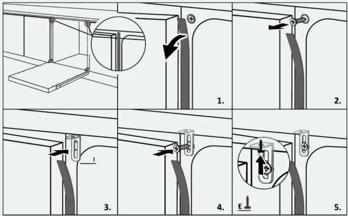
⚠ WARNING: If it is not possible to secure the dishwasher laterally, use the supplied brackets and secure it to the worktop; take care if it is not made of wood.
WELCOME
3.
2.
2.
WELCOME
3.
7.5 Setting the slope
2.
Transfer the dimension to the kitchen panel and determine the center;
3.
7.8 Preparing the panel
4.
2.
5.
WELCOME
3.
2.
2.
7.9 Panel installation
4.
5.
WELCOME
3.
7.2 Height adjustment
2.
7.8 Panel preparation
4.
2.
7.9 Panel installation
4.
WELCOME
3.
2.
2.
5.
WELCOME
3.
7.2 Height adjustment
2.

2.
5.
WELCOME
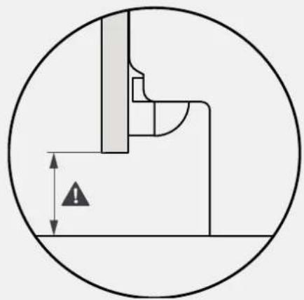
⚠ CAUTION: The minimum height of the dishwasher is 818 mm; in this case, the distance between the kitchen door and the floor must be between 90 and 120 mm. If the dishwasher is raised (max. 898 mm), the distance between the door and the floor must increase proportionally up to a maximum of between 170 and 200 mm.
3.
2.
Measure the kitchen panel and determine the center;
3.
Install the drilling template and follow the included instructions;
7.8 Panel preparation
4.
Remove the template and install the accessories;
2.
5.
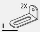
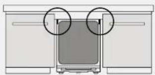
⚠ WARNING: If you cannot secure the dishwasher laterally, use the provided brackets and attach it to the work surface; be careful if the work surface material is not wood.

3.
7.5 Leveling adjustment
2.
7 Dishwasher installation instructions
7.9 Panel installation
1.
2.
7.9 Ceiling installation
4.
5.

TERE TULEMAST
3.
7.5 Adjusting the angle
7.7 Attaching the front legs
2.
7.8 Preparing the panel
4.
2.
7.9 Installing the panel
4.
PLEASE CLICK
or by clicking on this link

3.
2.
2.
7.9 Panel installation
4.
5.
WELCOME
2.
2.
5.
WELCOME
or by clicking on the following

5 Installation tools
Required tools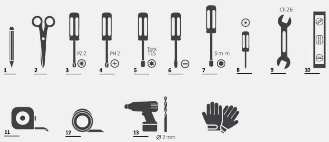
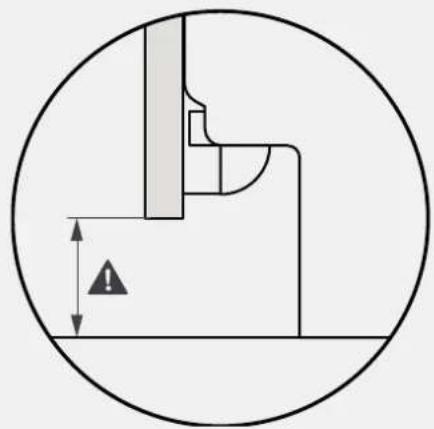
⚠ WARNING: The minimum height of the dishwasher is 818 mm; in that case, the distance between the kitchen door and the floor must be between 90 and 120 mm. If the dishwasher is raised (max. 898 mm), this distance must also be increased proportionally, up to a maximum of between 170 and 200 mm.
7 Installation instructions for the dishwasher
7.1 Installing the steam strip
3.
7.2 Adjusting the height
7.3 Adjusting the rear foot
Adjust the height of the rear foot from the front of the machine according to the instructions.
7 Installation instructions for the dishwasher
7.4 Adjusting the height of the front feet
Act directly on the front feet. If necessary, slightly lift the dishwasher.
7.5 Adjusting the tilt
Align the dishwasher vertically and horizontally.
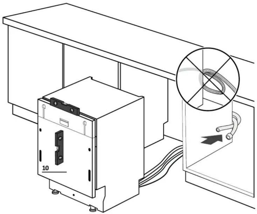
7.6 Inserting into the built-in space
2.
7.8 Panel preparation
4.
Remove the template and install the accessories.
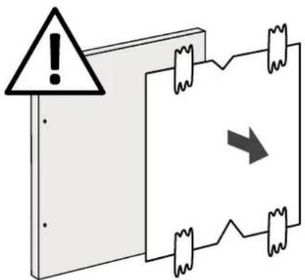
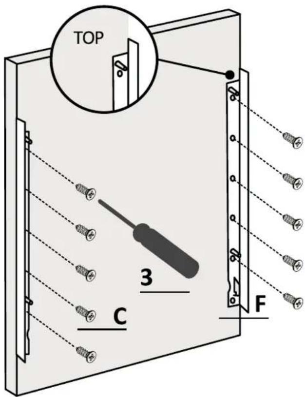
⚠️ WARNING: Avoid having the screw heads protrude from the back of the panel when installing the handle.
7 Installation instructions for the dishwasher
7.9 Panel installation
1.
Attach the panel to the dishwasher;
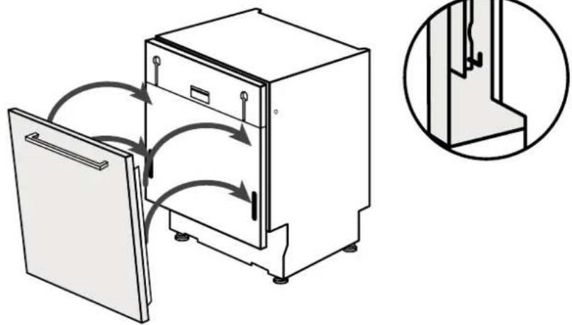
2.
Attach the panel to the lower part of the dishwasher;
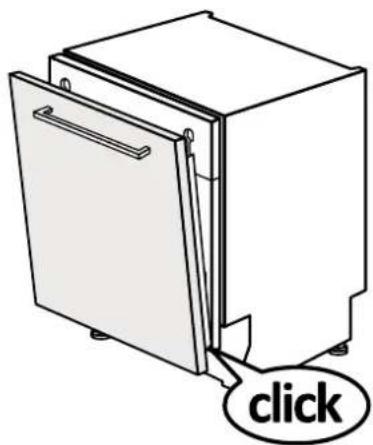
3.
Attach the panel to the upper part of the dishwasher;
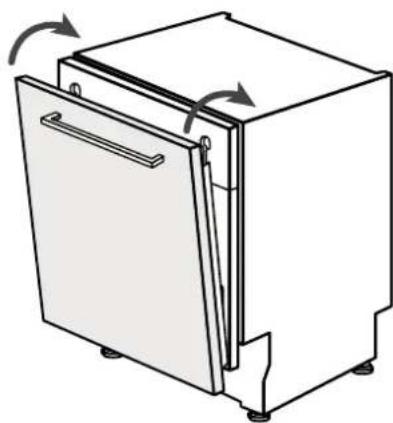
7.9 Panel installation
4.
Open the dishwasher door while holding the lower part of the kitchen panel, then unscrew the lower screws;
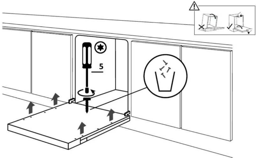
5.
Check that the panel is fully inserted; attach the kitchen panel to the dishwasher using the supplied screws.
7 Installation instructions for the dishwasher
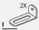
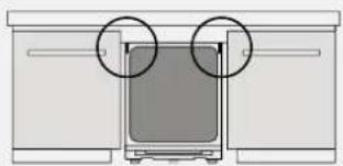
⚠ WARNING: If you cannot secure the dishwasher laterally, use the supplied brackets and attach it to the worktop; be careful if the worktop material is not wood.
WELCOME
3.
7.2 Height adjustment
7.5 Angle adjustment
2.
7.9 Installation of the panel
1.
2.
7.9 Installation of the panel
4.

WELCOME
3.
7.2 Height adjustment
Tilt the dishwasher by lifting the rear about 10 cm.
7.3 Rear foot adjustment
2.
2.
7.9 Panel installation
4.
WELCOME
3.
7.2 Height adjustment
7.5 Angle adjustment
2.
2.
5.
WELCOME
3.
7.2 Height adjustment
7.5 Angle adjustment
2.
2.
WELCOME!
or by clicking this

2.
2.
WELCOME
3.
7.2 Height adjustment
7.5 Tilt adjustment
2.
2.
7.9 Mounting panel
4.
5.
- WELCOME
- INDEX
- SAFETY WARNINGS FOR INSTALLATION
- OBSERVE THESE DIRECTIONS BEFORE BEGINNING THE INSTALLATION OF THE PRODUCT. YOUR SAFETY IS VERY IMPORTANT TO US. PLEASE READ THIS INFORMATION CAREFULLY BEFORE USING THE PRODUCT
- WHERE TO INSTALL THE DISHWASHER
- DISHWASHER DIMENSIONS
- STEP-BY-STEP INSTALLATION VIDEO
- INSTALLATION TOOLS
- INSTRUCTIONS FOR DISHWASHER INSTALLATION
- STEAM BAND INSTALLATION
- HEIGHT ADJUSTMENT
- REAR FOOT ADJUSTMENT
- FRONT FEET ADJUSTMENT
- TILT ADJUSTMENT
- INSERTION INTO THE BUILT-IN COMPARTMENT
- FIXING THE FRONT FEET
- PANEL PREPARATION
- INSTALLATION OF THE PANEL
- FIXING THE MACHINE TO THE KITCHEN
- DRAIN WATER AND ELECTRICITY CONNECTION
- CONNECTION DIAGRAM
- SAFETY DEVICES
- DELIVERY TO THE USER
- DISHWASHER DISASSEMBLY
- PLATE INSTALLATION
- ADJUSTING THE REAR FOOT
- DISHWASHER INSTALLATION INSTRUCTIONS
- INSTALLING THE ANTI-CONDENSATION STRIP
- SECURING THE FRONT FEET
- INSTALLATION INSTRUCTIONS FOR THE DISHWASHER
- PREPARING THE COUNTERTOP
- INSTALLING THE COUNTERTOP
- PANEL INSTALLATION
- SECURING THE DISHWASHER TO THE KITCHEN
- SETTING THE SLOPE
- PREPARING THE PANEL
- LEVELING ADJUSTMENT
- CEILING INSTALLATION
- TERE TULEMAST
- ADJUSTING THE ANGLE
- ATTACHING THE FRONT LEGS
- INSTALLING THE PANEL
- PLEASE CLICK
- INSTALLING THE STEAM STRIP
- ADJUSTING THE HEIGHT
- ADJUSTING THE HEIGHT OF THE FRONT FEET
- ADJUSTING THE TILT
- INSERTING INTO THE BUILT-IN SPACE
- ANGLE ADJUSTMENT
- MOUNTING PANEL
Brand : HOOVER
Model : HI 5C6F0S-80
Category : Dishwasher